Table of Contents
Advertisement
Quick Links
Advertisement
Table of Contents

Subscribe to Our Youtube Channel
Related Manuals for LevelOne WBR-6013


Summary of Contents for LevelOne WBR-6013
-
Page 1: User Manual
LevelOne User Manual WBR-6013 Version : v1.0_20161221... -
Page 2: Table Of Contents
Table of Contents Introduction ............7 Features ................. 7 Device Requirements ............7 Using this Document ............. 8 Notational conventions ........... 8 Typographical conventions ..........8 Special messages ............8 Getting Support ..............8 Getting to know the device ........9 Computer / System requirements ......... - Page 3 Quick Setup ............45 Operation Mode Setup ............46 Gateway ................ 46 Bridge ................47 Wireless ISP..............48 WAN Interface Setup ............49 Static IP ................. 49 DHCP Client ..............50 PPPoE ................50 PPTP ................51 L2TP ................52 Wireless Basic Settings ............
- Page 4 Deny Listed ..............81 WDS settings ............... 82 ConfigureWDS (Wireless Distribution System) only .............. 83 ConfigureAP (Access Point) + WDS (Wireless Distribution System) ......... 87 Site Survey ................92 ConfigureWireless ISP + Wireless client +Site Survey .............. 93 WPS ..................97 Introduction of WPS............
- Page 5 TUNNEL (6 OVER 4) ............159 Port Filtering ............. 160 Port filtering for TCP port 80 ..........161 Port filtering for UDP port 53 ..........163 IP Filtering ............165 IP filtering for TCP with specified IP ......... 166 IP filtering for UDP with specified IP ......... 168 IP filtering for both TCP and UDP with specified IP ..............
- Page 6 Load Settings from File ............. 208 Resetting to Defaults ............210 Password ............212 Setting your username and password ......212 Configuring your Computers ......214 Configuring Ethernet PCs ..........214 Before you begin ............214 Windows® XP PCs ............ 214 Windows 2000 PCs ............
-
Page 7: Introduction
Internet using your high-speed xDSL/Cable modem connection. This User Guide will show you how to connect your WBR-6013, and how to customize its configuration to get the most out of your new product. -
Page 8: Using This Document
Acronyms are defined the first time they appear in the text and also in the glossary. For brevity, the WBR-6013 is referred to as “the device”. The term LAN refers to a group of Ethernet-connected computers at one site. -
Page 9: Getting To Know The Device
Getting to know the device Computer / System requirements Windows 98SE, Windows Me, Windows 2000, Windows XP, Windows Vista, Windows 7, Windows 8, Windows 8.1 and Windows 10 Package Contents 1. WBR-6013 2. Quick Installation Guide 3. Ethernet Cable (RJ-45) 4. Power Adapter... -
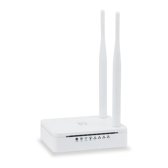
Page 10: Led Meanings & Activations
LED meanings & activations Front Panel The front panel contains lights called Light Emitting Diodes (LEDs) that indicate the status of the unit. * Actual Front Panel and ANTENNA may vary depending on model. Figure 1: Front Panel and LEDs Label Color Function... - Page 11 Press this button for at least 3 full second to turn off/on wireless signals RESET Reset button. RESET the WBR-6013 to its default settings. Press this button for at least 6 full seconds to RESET device to its default settings.
-
Page 12: Computer Configurations Under Different Os, To Obtain Ip Address Automatically
Computer configurations under different OS, to obtain IP address automatically Before starting the WBR-6013 configuration, please kindly configure the PC computer as below, to have automatic IP address / DNS Server. For Windows 98SE / ME / 2000 / XP 1. - Page 13 2. Single RIGHT click on "Local Area connection", then click "Properties".
- Page 14 3. Double click on "Internet Protocol (TCP/IP)".
- Page 15 4. Check "Obtain an IP address automatically" and "Obtain DNS server address automatically" then click on "OK" to continue. 5. Click "Show icon in notification area when connected" (see screen image in 3. above) then Click on "OK" to complete the setup procedures.
-
Page 16: For Windows Vista-32/64
For Windows Vista-32/64 1. Click on “Start” -> “Control Panel” -> “View network status and tasks”. - Page 17 2. In the Manage network connections, click on “Manage network connections” to continue.
- Page 18 3. Single RIGHT click on "Local Area connection", then click "Properties".
- Page 19 4. The screen will display the information "User Account Control" and click "Continue" to continue. 5. Double click on "Internet Protocol Version 4 (TCP/IPv4)".
- Page 20 6. Check "Obtain an IP address automatically" and "Obtain DNS server address automatically" then click on "OK" to continue.
-
Page 21: For Windows 7/8/8.1/10-32/64
For Windows 7/8/8.1/10-32/64 1. Right click on Network icon , then click "Open Network and Sharing Center". 1. In the Control Panel Home, click on “Change adapter settings” to continue. - Page 22 2. Single RIGHT click on “Ethernet", then click "Properties".
- Page 23 3. Double click on "Internet Protocol Version 4 (TCP/IPv4)".
- Page 24 4. Check "Obtain an IP address automatically" and “Obtain DNS server address automatically” then click on "OK" to continue.
-
Page 25: Connecting Your Device
Connecting your device This chapter provides basic instructions for connecting the WBR-6013 to a computer or LAN and to the Internet. In addition to configuring the device, you need to configure the Internet properties of your computer(s). For more details, see the following sections: ... - Page 26 Step 2. Connect the Ethernet cable to LANPort Connect the supplied RJ45 Ethernet cable from your PC's Ethernet port to any of the 4 WBR-6013 LAN Ports. Step 3. Attach the power connector Connect the power adapter to the power inlet “POWER” of the 802.11n WLAN Router and turn the power switch...
-
Page 27: Advanced Configuration
Advanced Configuration Advanced Configuration 1. From any of the LAN computers, launch your web browser, type the following URL in the web address (or location) box, and press [Enter] on your keyboard: http://192.168.1.1 2. Please enter the User Name: admin and Password: admin and then click on OK button. -
Page 28: Wan Interface Setup
WAN Interface Setup Examples 8-1. DHCP client From the WAN Access Type drop-down list, select DHCP Client If you are happy with your settings, click onNext 8-2. Static IP... - Page 29 From the WAN Access Type drop-down list, select Static IPsetting. Enter IP Address, Subnet Mask, Default Gatewayand DNS which was given by Telecom or by your Internet Service Provider (ISP). If you are happy with your settings, click onNext 8-3. PPPoE From the WAN Access Type drop-down list, select PPPoEsetting.
- Page 30 From the WAN Access Type drop-down list, select PPTP setting provided by your Network Administrator or ISP. Click on the ratio of Dynamic IP (DHCP) or Static IP. Enter IP Address for example 172.1.1.1 provided by your Network Administrator or ISP. (for Static IP only) Enter Subnet Mask for example 255.255.0.0 provided by your Network Administrator or ISP.
- Page 31 From the WAN Access Type drop-down list, select L2TP setting provided by your Network Administrator or ISP. Click on the ratio of Dynamic IP (DHCP) or Static IP. Enter IP Address for example 172.1.1.1 provided by your Network Administrator or ISP. (for Static IP only) Enter Subnet Mask for example 255.255.0.0 provided by your Network Administrator or ISP.
-
Page 32: Wirelessconfiguration
WirelessConfiguration 5. Enter SSID. 6. Click on Next. 7. From the Encryption list, choose the Encryption type and enter related parameters if necessary, as None / WEP / WPA2(AES) and WPA Mixed Mode (the default settings Security Mode = None). For example, the Encryption you choose is None. -
Page 33: Wireless Connection
9. Change setting successfully! Do not turn off or reboot the Device during this time. Please wait 20 seconds ... 10. Now, the WBR-6013 has been configured completely, and suitable for Wireless and Internet Connections. Wireless Connection For easy installation it is saved to keep the settings. You can later change the wireless settings via the wireless configuration menu. -
Page 34: What The Internet/Wan Access Of Your Own Network Now Is
which could be found on the bottom side of the device). You can later change this network key via the wireless configuration menu. 15. Click on "Next". 16. Now you are ready to use the Wireless Network to Internet or intranet. What the Internet/WAN access of your own Network now is Now you could check what the Internet/WAN access of your... - Page 35 1. Click Start -> Control Panel 2. Double click Network Connections...
-
Page 36: Internet/Wan Access Is The Dhcp Client
Internet/WAN access is the DHCP client If you cannot see any Broadband Adapter in the Network Connections, your Internet/WAN access is DHCP Client or Static IP. -
Page 37: Internet/Wan Access Is The Static Ip
3. Click Local Area Connection in LAN or High-Speed Internet and you could see string Assigned by DHCP Details. Internet/WAN access is the Static IP If you cannot see any Broadband Adapter in the Network Connections, your Internet/WAN access is DHCP Client or Static IP. - Page 38 4. Click Local Area Connection in LAN or High-Speed Internet and you could see string Manually Configured Details. 5. Right click Local Area Connection and click Properties and then you could get the IP settings in detail and write down the IP settings as follow:...
-
Page 39: Internet/Wan Access Is The Pppoe Client
IP Address: 192.168.10.110 Subnet mask: 255.255.255.0 Default gateway: 192.168.10.100 Preferred DNS server: 192.168.10.100 Alternate DNS Server: If you have it, please also write it down. Internet/WAN access is the PPPoE client If you can see any Broadband Adapter in the Network Connections, your Internet/WAN access is PPPoE Client. -
Page 40: Getting Started With The Web Pages
Password of PPPoE: 1234 for example Getting Started with the Web pages The WBR-6013 includes a series of Web pages that provide an interface to the software installed on the device. It enables you to configure the device settings to meet the needs of your... -
Page 41: Accessing The Web Pages
network. You can access it through your web browser from any PC connected to the device viathe LAN ports. Accessing the Web pages To access the Web pages, you need the following: A PC or laptop connected to the LAN port on the device. ... -
Page 42: Testing Your Setup
Figure 6: Login screen 1. Enter your user name and password. The first time you log into the program, use these defaults: User Name: admin Password: admin You can change the password at any time or you can configure your device so that you do not need to enter a password. -
Page 43: Default Device Settings
Default device settings In addition to handling the xDSL / Cable modem connection to your ISP, the WBR-6013 can provide a variety of services to your network. The device is preconfigured with default settings for use with a typical home or small office network. - Page 44 See Network Settings -> LAN Interface. Subnet mask: 255.255.255.0 DHCP (Dynamic DHCP server enabled with the The WBR-6013 maintains a pool of private IP Host Configuration following pool of addresses: addresses for dynamic assignment to your LAN Protocol) computers. To use this service, you must have set up 192.168.1.100...
-
Page 45: Quick Setup
Quick Setup The Quick Setup page displays useful information about the setup of your device, including: details of the device’s Internet access settings details of the device’s Wireless settings To display this page: 1. From the head menu, click on SETUP. Figure 7: Quick Setup page... -
Page 46: Operation Mode Setup
Operation Mode Setup You can setup different modes to LAN and WLAN interface for NAT function. Gateway In this mode, the device is supposed to connect to internet via ADSL/Cable Modem. The NAT is enabled and PCs in four LAN ports share the same IP to ISP through WAN port. -
Page 47: Bridge
Bridge In this mode, all ethernet ports and wireless interface are bridged together and NAT function is disabled. All the WAN related function and firewall are not supported. To change the Operation Mode: 1. From the left-hand menu, click on Wizard. The following page is displayed: 2. -
Page 48: Wireless Isp
Wireless ISP In this mode, all ethernet ports are bridged together and the wireless client will connect to ISP access point. The NAT is enabled and PCs in ethernet ports share the same IP to ISP through wireless LAN. You must set the wireless to client mode first and connect to the ISP AP in Site-Survey page. -
Page 49: Wan Interface Setup
WAN Interface Setup This page is used to configure the parameters for Internet network which connects to the WAN port of your Access Point. Here you may change the access method to static IP, DHCP, PPPoE, PPTPor L2TP by click the item value of WAN Access type. -
Page 50: Dhcp Client
DHCP Client In this mode, the device is supposed to connect to internet via ADSL/Cable Modem. The NAT is enabled and PCs in four LAN ports share the same IP to ISP through WAN port. The connection type can be setup in WAN page by using DHCP Client. -
Page 51: Pptp
PPTP In this mode, the device is supposed to connect to internet via ADSL/Cable Modem. The NAT is enabled and PCs in four LAN ports share the same IP to ISP through WAN port. The connection type can be setup in WAN page by using PPTP. 1. -
Page 52: L2Tp
L2TP In this mode, the device is supposed to connect to internet via ADSL/Cable Modem. The NAT is enabled and PCs in four LAN ports share the same IP to ISP through WAN port. The connection type can be setup in WAN page by using L2TP. 1. -
Page 53: Wireless Basic Settings
Wireless Basic Settings This page is used to configure the parameters for wireless LAN clients which may connect to your Access Point. -
Page 54: Ap (Access Point)
AP (Access Point) Access Point is used to configure the parameters for wireless LAN clients who may connect to your Access Point. 1. From the Band drop-down list, select a Band. 2. From the Mode drop-down list, select AP setting. 3. -
Page 55: Client
Client This page is used to configure the parameters for wireless LAN clients which may connect to your Access Point. 1. From the Band drop-down list, select a Band. 2. From the Mode drop-down list, select Client setting. 3. From the Network Type drop-down list, select a Type. 4. -
Page 56: Wds (Wireless Distribution System)
WDS (Wireless Distribution System) WDS stands for Wireless Distribution System. It enables the access points (APs) to be connected wirelessly. 802.11n WLAN AP Router can also provide you services of WDS. 802.11n WLAN AP Router that supports WDS does not support security systems like WEP, WPA or WPA-Enterprise on a WDS Note network. - Page 57 Main WDS station: One of your WDS stations is the main base station forthe WDS network. This AP is connected directly to your Internet connection,or connected to your router via a wired connection. The main stationis the bridge to your Internet connection that all wireless trafficeventually flows through.
- Page 58 You set the SSID of the remote location(s) using either a unique nameor by using the same SSID as you use for your main base station.(Whoa, our heads just exploded!) Using the same SSID (a “roaming” network)is pretty cool. You associate with one AP one time and then yourPC or Mac can associate with any AP on your WDS network without youhaving to do anything —...
-
Page 59: Wds (Wireless Distribution System) Only
WDS (Wireless Distribution System) only 1. From the Band drop-down list, select a Band. 2. From the Mode drop-down list, select WDS setting. 3. From the Channel Width drop-down list, select a Channel Width. 4. From the ControlSideband drop-down list, select a ControlSideband. -
Page 60: Ap (Access Point) + Wds (Wireless Distribution System)
AP (Access Point) + WDS (Wireless Distribution System) Access Point is used to configure the parameters for wireless LAN clients which may connect to your Access Point. 1. From the Band drop-down list, select a Band. 2. From the Mode drop-down list, select AP+WDS setting. 3. -
Page 61: Wireless Security Setup
Wireless Security Setup This page allows you setup the wireless security. Turn on WEP or WPA by using Encryption Keys could prevent any unauthorized access to your wireless network. You can protect your wireless data from potential eavesdroppers by encrypting wireless data transmissions. An eavesdropper might set up a compatible wireless adapter within range of your device and attempt to access your network. - Page 62 To configure security, choose one of the following options: If you do not want to use Wireless Network security, From the Encryption drop-down list, select None setting and then click Finished.None is the default setting, but you are strongly recommended to use wireless network security on your device.
-
Page 63: Configuring Wep64Bit Ascii (5 Characters) Security
Configuring WEP64bit ASCII (5 characters) security The example set in this section is for 64bit encryption. 1. From the Encryption drop-down list, select WEP setting. 2. From the Key Length drop-down list, select 64-bit setting. 3. From the Key Format drop-down list, select ASCII (5 characters) setting. -
Page 64: Configuring Wep 128Bit Ascii (13 Characters) Security
Configuring WEP 128bit ASCII (13 characters) security The example set in this section is for 128bit encryption. 1. From the Encryption drop-down list, select WEP setting. 2. From the Key Length drop-down list, select 128-bit setting. 3. From the Key Format drop-down list, select ASCII (13 characters) setting. -
Page 65: Configuring Wpa2 (Aes) Hex (64 Characters)Security
Configuring WPA2 (AES) Passphrase security The example set in this section is for WPA2 (AES) Passphrase encryption. 1. From the Encryption drop-down list, select WPA2 (AES) setting. 2. From the Pre-Shared Key Format drop-down list, select Passphrase setting. 3. Type the Pre-Shared Key. 4. - Page 66 9. Change setting successfully! Do not turn off or reboot the Device during this time. Please wait 20 seconds ...
-
Page 67: Operation Mode
Operation Mode This chapter describes how to configure the way that your device connects to the Internet. There are Three options of Operation Mode: Gateway, Bridgeand Wireless ISP. Setting Operation Mode To change the Operation Mode: 1. From the head menu, click on SETUP. 2. -
Page 68: Wireless Network - Wlan1
Wireless Network - WLAN1 This chapter assumes that you have already set up your Wireless PCs and installed a compatible Wireless card on your device. See Configuring Wireless PCs. Basic Settings The Wireless Network page allows you to configure the Wireless features of your device. - Page 69 2. From the left-hand Wirelessmenu, click onBasic Settings. The following page is displayed:...
- Page 70 Figure 8: Wireless Network page Field Description Disable Enable/Disable the Wireless LAN Interface. Wireless LAN Default: Disable Interface Band Specify the WLAN Mode Mode Configure the Wireless LAN Interface to AP, Client, WDS orAP + WDS mode Network Type Configure the Network Type to Infrastructure or Ad hoc. SSID Specify the network name.
-
Page 71: Advanced Settings
Advanced Settings These settings are only for more technically advanced users who have a sufficient knowledge about wireless LAN. These settings should not be changed unless you know what effect the changes will have on your Access Point. To access the Wireless NetworkAdvanced Settings page: 1. -
Page 72: Security
IAPP Disable or Enable IAPP Protection A protection mechanism prevents collisions among 802.11g nodes. Aggregation Disable or Enable Aggregation Short GI Disable or Enable Short GI WLAN Partition Disable or Enable WLAN Partition STBC Disable or Enable STBC LDPC Disable or Enable LDPC Disable or Enable TX Beamforming Beamforming RF Output... - Page 73 Field Description Select SSID Select the SSID Encryption Configure the Encryption to Disable, WEP, WPA , WPA2 or WPA-Mixed Use 802.1x Use 802.1x Authentication by WEP 64bits or WEP 128bits Authentication Authentication Configure the Authentication Mode to Open System, Shared Key or Auto Key Length Select the Key Length 64-bit or 128-bit...
-
Page 74: Wep + Encryption Key
WEP + Encryption Key WEP aims to provide security by encrypting data over radio waves so that it is protected as it is transmitted from one end point to another. However, it has been found that WEP is not as secure as once believed. -
Page 75: Wep + Use 802.1X Authentication
9. Change setting successfully! Do not turn off or reboot the Device during this time. Please wait 20 seconds ... WEP + Use 802.1x Authentication WEP aims to provide security by encrypting data over radio waves so that it is protected as it is transmitted from one end point to another. -
Page 76: Wpa2/Wpa Mixed + Personal (Pre-Shared Key)
7. Change setting successfully! Do not turn off or reboot the Device during this time. Please wait 20 seconds ... WPA2/WPA Mixed + Personal (Pre-Shared Key) Wi-Fi Protected Access (WPA and WPA2) is a class of systems to secure wireless (Wi-Fi) computer networks. -
Page 77: Wpa2/Wpa Mixed + Enterprise (Radius)
6. Enter the Pre-Shared Key depending on selected Passphrase or Hex (64 characters). 7. Click on Save & Apply button to confirm and return. 8. Change setting successfully! Do not turn off or reboot the Device during this time. Please wait 20 seconds ... WPA2/WPA Mixed + Enterprise (RADIUS) Wi-Fi Protected Access (WPA and WPA2) is a class of systems to secure wireless (Wi-Fi) computer networks. - Page 78 5. Enter the Port, IP Address andPassword of RADIUS Server: 6. Change setting successfully! Do not turn off or reboot the Device during this time. Please wait 20 seconds ...
-
Page 79: Access Control
Access Control For security reason, using MAC ACL's (MAC Address Access List) creates another level of difficulty to hacking a network. A MAC ACL is created and distributed to AP so that only authorized NIC's can connect to the network. While MAC address spoofing is a proven means to hacking a network this can be used in conjunction with additional security measures to increase the level of complexity of the network security... -
Page 80: Allow Listed
Allow Listed If you choose 'Allowed Listed', only those clients whose wireless MAC addresses are in the access control list will be able to connect to your Access Point. 1. From the Wireless Access Control Mode drop-down list, select Allowed Listedsetting. 2. -
Page 81: Deny Listed
Deny Listed When 'Deny Listed' is selected, these wireless clients on the list will not be able to connect the Access Point. 1. From the Wireless Access Control Mode drop-down list, select Deny Listedsetting. 2. Enter the MAC Address. 3. Enter the Comment. 4. -
Page 82: Wds Settings
WDS settings Wireless Distribution System uses wireless media to communicate with other APs, like the Ethernet does. To do this, you must set these APs in the same channel and set MAC address of other APs which you want to communicate with in the table and then enable the WDS. -
Page 83: Configurewds (Wireless Distribution System) Only
ConfigureWDS (Wireless Distribution System) only 1. From the head menu, click on WLAN1. 2. From the left-hand menu, click on Basic Settings. 3. From the Mode drop-down list, select WDS. 4. From the Channel Number drop-down list, select a Channel. 5. - Page 84 7. From the head menu, click on WLAN1. 8. From the left-hand menu, click on WDS settings. 9. Check on the optionEnable WDS. 10. Click the Set Security. 11. This page allows you setup the wireless security for WDS. When enabled, you must make sure each WDS device has adopted the same encryption algorithm and Key.
- Page 85 14. Change setting successfully! Do not turn off or reboot the Device during this time. Please wait 20 seconds ...
- Page 86 15. From the head menu, click on WLAN1. 16. From the left-hand menu, click on WDS settings. 17. Check on the optionEnable WDS. 18. Enter the MAC Address. 19. Enter the Comment. 20. Click the Save & Apply. 21. Change setting successfully! Do not turn off or reboot the Device during this time.
-
Page 87: Configureap (Access Point) + Wds (Wireless Distribution System)
23. From the left-hand menu, click on WDS settings. 24. The MAC Address that you created has been added in the Current Access Control List. ConfigureAP (Access Point) + WDS (Wireless Distribution System) 1. From the head menu, click on WLAN1. 2. - Page 88 8. From the head menu, click on WLAN1. 9. From the left-hand menu, click on WDS settings. 10. Check on the optionEnable WDS. 11. Click the Set Security.
- Page 89 12. This page allows you setup the wireless security for WDS. When enabled, you must make sure each WDS device has adopted the same encryption algorithm and Key. 13. Configure each field with the Encryption that you selected. 14. Click Save & Apply button. 15.
- Page 90 16. From the head menu, click on WLAN1. 17. From the left-hand menu, click on WDS settings. 18. Check on the optionEnable WDS. 19. Enter the MAC Address. 20. Enter the Comment. 21. Click the Save & Apply. 22. Change setting successfully! Do not turn off or reboot the Device during this time.
- Page 91 23. From the head menu, click on WLAN1. 24. From the left-hand menu, click on WDS settings. 25. The MAC Address that you created has been added in the Current Access Control List.
-
Page 92: Site Survey
Site Survey This page provides tool to scan the wireless network. If any Access Point or IBSS is found, you could choose to connect it manually when client mode is enabled. To access the Wireless NetworkWDS settingspage: 1. From the head menu, click on WLAN1. From the left-hand menu, click on Site Survey. -
Page 93: Configurewireless Isp + Wireless Client +Site Survey
ConfigureWireless ISP + Wireless client +Site Survey 2. From the head menu, click on SETUP. 3. From the left-hand Operation Modemenu, click on Wireless ISP Settings. 4. Config WAN Interface. 5. Click Save & Apply button. 6. Change setting successfully! Do not turn off or reboot the Device during this time. - Page 94 8. From the left-hand menu, click on Basic Settings. 9. From the Mode drop-down list, select Client. 10. Enter SSIDof the AP that you want to connect to for example AP_5G_A81261. If you don’t know what the SSID of the AP that you want to connect to, please skip this step. 11.
- Page 95 14. From the left-hand menu, click on Site Survey. 15. Click Site Survey button. 16. Now you could see the APs that scanned by the Wireless Gateway were listed below. 17. Click on the ratio of AP’s SSID under the item Select that you want the Wireless Gateway to connect to.
- Page 96 20. Please wait... 21. Check on Add to Wireless Profile. 22. Click Reboot Now button. 23. Change setting successfully! Please wait 20 seconds….
-
Page 97: Wps
This page allows you to change the setting for WPS (Wi-Fi Protected Setup). Using this feature could let your wireless client automatically synchronize its setting and connect to the Access Point in a minute without any hassle. To access the Wireless NetworkWPSpage: 1. -
Page 98: Introduction Of Wps
Field Description Push Button Clicking this button will invoke the PBC method of WPS. It is only Configuration used when AP acts as a registrar. Whenever users want to enable/disable WPS or change AP’s PIN, Save & Apply they need to apply this button to commit changes. It restores the original values of “Self-PIN Number”... -
Page 99: Ap Mode
Other modes such as WDS mode, Infrastructure-Adhoc mode, and the wireless virtual interface of Universal Repeater mode are not implemented with WPS features. If those unsupported modes are enforced by users, WPS will be disabled. Under the configuration of every WPS- supported mode, Wireless Gateway has Push Button method and PIN method. -
Page 100: Infrastructure-Client Mode
Infrastructure-Client mode In Infrastructure-Client mode, Wireless Gateway only supports enrollee’s role. If users click “Start PIN”, click “Start PBC”, or press the physical button on Wireless Gateway, it will start to seek WPS AP. Once users apply the same method on registrar side, Wireless Gateway will receive the wireless profile upon successfully doing the registration protocol. -
Page 101: Wireless Basic Settings - Wlan1Page
Wireless Basic Settings - WLAN1page Users need to make sure the “Broadcast SSID” file is set to “Enabled”. Otherwise, it might prevent WPS from working properly. -
Page 102: Operations Of Ap - Ap Being An Enrollee
Operations of AP - AP being an enrollee In this case, AP will be configured by any registrar either through in-band EAP or UPnP. Here, users do not need to do any action on AP side. They just need AP’s device PIN and enter it into registrar. - Page 103 4. Plug the Ethernet cable into AP’s LAN port and make sure the IP connection is valid with Vista. 5. Make sure WCN is enabled. Users may need to enable it at the first time. They could open the “Control Panel”, click “Classic View“, open “Administrative Tools”, double click “Services”, ”, a User Account Control pop up and click “Continue“, edit properties of “Windows Connect Now”,...
- Page 104 6. If the previous steps are done, open Windows Explorer. Go to the Network section. 7. Click on “Network discovery and file sharing are turned off. Network computers and devices are not visible. Click to Change…“...
- Page 105 8. Click on “Turn on network discovery and file sharing“...
- Page 106 9. Click on “No, make the network that I am connected to a private network“...
- Page 107 10. AP’s icon will show up. Double click on it.
- Page 108 11. Users could also Click “Add a wireless device” if the icon is not there. Click “next”.
- Page 109 12. Enter AP’s Self-PIN Numberand click “next”.
- Page 110 13. Choose a name that people who connect to your network will recognize.
- Page 111 14. Enter the Passphrase and then click Next.
- Page 112 15. A User Account Control screen pops up, click Continue. 16. AP is successfully configured by WCN.
- Page 113 17. Finally, AP will become configured (see WPS Status). The authentication algorithm, encryption algorithm, and key assigned by WCN will be displayed below “Current Key Info”.
- Page 114 18. The SSID field of Wireless Basic Settings page will also be modified with the value assigned by WCN.
- Page 115 19. The security settings on the Wireless Security Page will be modified by WCN, too. The warning message will show up if users try to modify the security settings. The reason is the same as we explained in the previous section.
-
Page 116: Operations Of Ap - Ap Being A Registrar
Operations of AP - AP being a registrar AP mode Whenever users enter station’s PIN into AP’s Wi-Fi Protected Setup page and click “Start PIN”, AP will become a registrar. Users must start the PIN method on the station side within two minutes. - Page 117 6. Users must start the PIN method on the station side within two minutes. 7. Users must start the PIN method on the station side within two minutes.
- Page 118 8. If the device PIN is correct and the WPS handshake is successfully doneon the station side, User’s Wi-Fi Protected status will be shown as below.
- Page 119 9. If the device PIN is correct and the WPS handshake is successfully done, AP’s Wi-Fi Protected Setup page will be shown as below. Other pages such as Wireless Basic Settings page and Wireless Security Setup page will also be updated appropriately as described in previous sections.
-
Page 120: Push Button Method
Push Button method Wireless Gateway supports a virtual button “Start PBC” on the Wi-Fi Protected Setup page for Push Button method. If userspush a virtual button “Start PBC”, AP will initiate a WPS session and wait for any station to join. At this moment, AP will detect whether there is more than one station that starts the PBC method. - Page 121 5. Users must start the PBC method on the station side within two minutes. 6. Users must start the PBC method on the station side within two minutes.
- Page 122 7. If the device PCB and the WPS handshake is successfully doneon the station side, User’s Wi-Fi Protected status will be shown as below.
- Page 123 8. If the device PIN is correct and the WPS handshake is successfully done, AP’s Wi-Fi Protected Setup page will be shown as below. Other pages such as Wireless Basic Settings page and Wireless Security Setup page will also be updated appropriately as described in previous sections.
-
Page 124: Wireless Schedule
Wireless Schedule This page allows you setup the wireless schedule rule. Please do not forget to configure system time before enable this feature. To access the Wireless Schedulepage: 1. From the head menu, click on WAN1. 2. From the left-hand menu, click on Wireless Schedule. The following page is displayed:... -
Page 125: Lan Interface
LAN Interface This chapter is to configure the parameters for local area network which connects to the LAN port of your Access Point. Here you may change the setting for IP address, subnet mask, DHCP, etc... You should only change the addressing details if your ISP asks you to, or if you are familiar with network configuration. - Page 126 Field Description IP Address The LAN IP address Default: 10.0.0.2 Subnet Mask The LAN netmask Default: 255.255.255.0 Default Gateway The LAN Gateway Default: 0.0.0.0 DHCP DHCP Type: Disable, DHCP Client or Server Default: DHCP Server DHCPClientRange Specify the starting/ending IP address of the IP address pool. Default Start IP: 10.0.0.100 Default Ending IP: 10.0.0.200 DHCP Lease Time...
-
Page 127: Changing The Lan Ip Address And Subnet Mask
Changing the LAN IP address and subnet mask To check the configuration of LAN Interface: 1. From the head menu, click on TCP/IP. 2. From the left-hand menu, click on LAN Setting. The following page is displayed:... - Page 128 3. Type IP Address andChange default LAN port IP address. 4. Click in the IP Address and Subnet Mask box and type a new IP Address and Subnet Mask. 5. Change the default DHCPClientRange. 6. Click Save & Apply. 7. Change setting successfully! Please wait 20 seconds….
- Page 129 You may also need to renew your DHCP lease: Windows 95/98 a. Select Run... from the Start menu. b. Enter winipcfg and click OK. c. Select your ethernet adaptor from the pull-down menu d. Click Release All and then Renew All. e.
-
Page 130: Show Client
Show Client To the IP Address, MAC Address, and Expired Time of the DHCP lease for each client computer/device: 1. From the head menu, click on TCP/IP. 2. From the left-hand menu, click on LAN Setting. The following page is displayed: 3. -
Page 131: Wan Interface
WAN Interface This chapter describes how to configure the way that your device connects to the Internet. Your ISP determines what type of Internet access you should use and provides you with any information that you need in order to configure the Internet access to your device. - Page 132 1. From the head menu, click on TCP/IP. 2. From the left-hand menu, click on WAN Setting. The following page is displayed:...
- Page 133 Option Description Static IP Choose this option if you are a leased line user with a fixed IP address. Access DHCP Client Choose this option if you are connected to the Internet Type through a Cable modem line. PPPoE Choose this option if you are connected to the Internet through a DSL line PPTP Choose this option if you are connected to the PPTP...
- Page 134 Option Description Clone MAC Address Clone MAC lets the device identify itself as another computer or device Enable uPNP Enable or Disable uPNP Enable IGMP Proxy Enable or Disable IGMP Proxy Enable Ping Access on WAN Enable or Disable Ping Access on WAN Enable Web Server Access on Enable or Disable Web Server Access on WAN Enable IPsec pass through on...
-
Page 135: Configuring Static Ip Connection
Configuring Static IP connection If you are a leased line user with a fixed IP address, enter in the IP address, subnet mask, gateway address, and DNS (domain name server) address(es) provided to you by your ISP. If your ISP wants you to connect to the Internet using Static IP, follow the instructions below. - Page 136 3. From the WAN Access Typedrop-down list, select Static IPsetting. 4. EnterWAN IP Address,WAN Subnet Mask, Default Gateway andDNS which was given by Telecom or by your Internet Service Provider (ISP). 5. Click Save & Apply.
-
Page 137: Configuring Dhcp Client Connection
6. Change setting successfully! Please wait 20 seconds…. Configuring DHCP Client connection Dynamic Host Configuration Protocol (DHCP), Dynamic IP (Get WAN IP Address automatically). If you are connected to the Internet through a Cable modem line, then a dynamic IP will be assigned. - Page 139 3. From the WAN Access Typedrop-down list, select DHCP Clientsetting. 4. Click Save & Apply.
-
Page 140: Configuring Pppoe Connection
5. Change setting successfully! Please wait 20 seconds…. Configuring PPPoE connection If your ISP’s Internet service uses PPPoE you need to set up a PPP login account. The first time that you login to the Internet, your ISP will ask you to enter a username and password so they can check that you are a legitimate, registered Internet service user. - Page 142 3. From the WAN Access Typedrop-down list, select PPPoEsetting. 4. EnterUser Name/Password provided by your ISP. Type them in the relevant boxes. 5. Click Save & Apply.
-
Page 143: Configuring Pptp Connection
6. Change setting successfully! Please wait 20 seconds…. Configuring PPTP connection If your ISP/Network Administrator wants you to connect to the Internet using PPTP, follow the instructions below. 1. From the head menu, click on TCP/IP. 2. From the left-hand menu, click on WAN Setting. The following page is displayed:... - Page 144 3. From the WAN Access Type drop-down list, select PPTP setting. 4. Enter IP Address/Subnet Mask/Default Gateway provided by your ISP. Type them in the relevant boxes. (for Static IP only) 5. Select PPTP Server Mode. 6. Enter Server Domain Address/User Name/Password provided by your ISP.
- Page 146 8. Change setting successfully! Please wait 20 seconds….
-
Page 147: Configuring L2Tp Connection
Configuring L2TP connection If your ISP/Network Administrator wants you to connect to the Internet using L2TP, follow the instructions below. 1. From the head menu, click on TCP/IP. 2. From the left-hand menu, click on WAN Setting. The following page is displayed:... - Page 148 3. From the WAN Access Type drop-down list, select L2TP setting. 4. Enter IP Address/Subnet Mask/Default Gateway provided by your ISP. Type them in the relevant boxes. (for Static IP only) 5. Select L2TP Server Mode. 6. Enter Server Domain Address/User Name/Password provided by your ISP.
-
Page 150: Configuring L2Tp Connection
8. Change setting successfully! Please wait 20 seconds…. Configuring L2TP connection If your ISP/Network Administrator wants you to connect to the Internet using L2TP, follow the instructions below. 9. From the head menu, click on TCP/IP. 10. From the left-hand menu, click on WAN Setting. The following page is displayed:... -
Page 151: Clone Mac Address
11. From the WAN Access Type drop-down list, select DS-Lite setting. 12. Configure related settings provided by your ISP. Type them in the relevant boxes. 13. Click Save & Apply. 14. Change setting successfully! Please wait 20 seconds…. Clone MAC Address Some particularly ISPs do not want you to have a home network and have a DSL/Cable modem that allows only 1 MAC to talk on the internet. - Page 152 2. From the left-hand menu, click on WAN Setting. The following page is displayed:...
- Page 153 3. Enterthe MAC for example 0123456789ab that you want to be instead of in the Clone MAC Addressfield. 4. If you enter 12 digits of 0in the Clone MAC Addressfield, it’ll disable Clone MAC Address function. 5. Click Save & Apply.
- Page 154 6. Change setting successfully! Please wait 20 seconds….
-
Page 155: Ipv6
IPV6 IPV6 WAN SETTING This page is used to configure the parameters for Internet network which connects to the WAN port of your Access Point. Here you may change the access method to static IP, DHCP, PPPoE, Bridge by click the item value of WAN Access type. 1. -
Page 156: Ipv6 Lan Setting
IPV6 LAN SETTING 1. From the head menu, click on IPV6. 2. From the left-hand menu, click on IPV6 LAN SETTING. The following page is displayed:... -
Page 157: Radvd
RADVD 1. From the head menu, click on IPV6. 2. From the left-hand menu, click on RADVD. The following page is displayed:... -
Page 159: Tunnel (6 Over 4)
TUNNEL (6 OVER 4) 1. From the head menu, click on IPV6. 2. From the left-hand menu, click on TUNNEL (6 OVER 4). The following page is displayed:... -
Page 160: Port Filtering
Port Filtering Entries in Current Filter Table are used to restrict certain ports and types of data packets from your local network to Internet through the Gateway. Use of such filters can be helpful in securing or restricting your local network. 1. -
Page 161: Port Filtering For Tcp Port 80
You must ensure that the single port or range specified does not overlap with a port or range for an existing common or custom Note application. Check the common port ranges listed in. Port filtering for TCP port 80 Please follow example below to deny the TCP port 80 for both Outbound and Inbound packet. - Page 162 3. Check the option Enable Port Filtering to enable the port filtering. 4. Enter80 and 80in PortRange field. 5. From the Protocol drop-down list, select TCPsetting. 6. EnterHTTP in Comment field. 7. Click Save & Apply. 8. Now the port filter that you created has been added and listed in the Current Filter Table.
-
Page 163: Port Filtering For Udp Port 53
Port filtering for UDP port 53 Please follow example below to deny the UDP port 53 for both Outbound and Inbound packet. 1. From the head menu, click on Firewall. 2. From the left-hand menu, click on Port Filtering. The following page is displayed:... - Page 164 3. Check the option Enable Port Filtering to enable the port filtering. 4. Enter53 and 53in PortRange field. 5. From the Protocol drop-down list, select UDPsetting. 6. EnterDNS Resolve in Comment field. 7. Click Save & Apply. 8. Now the port filter that you created has been added and listed in the Current Filter Table.
-
Page 165: Ip Filtering
IP Filtering Entries in this table are used to restrict certain types of data packets from your local network to Internet through the Gateway. Use of such filters can be helpful in securing or restricting your local network. The IP filter feature enables you to create rules that control the forwarding of incoming and outgoing data between the LAN and WAN side. -
Page 166: Ip Filtering For Tcp With Specified Ip
1. From the head menu, click on Firewall. 2. From the left-hand menu, click on IP Filtering. The following page is displayed: IP filtering for TCP with specified IP Please follow example below to deny the TCP protocol for specified IP. 1. - Page 167 2. From the left-hand menu, click on IP Filtering. The following page is displayed: 3. Check the option Enable IP Filtering to enable the IP Filtering. 4. Enterthe IP Address that you want to be deniedin Loal IP Address field. 5.
-
Page 168: Ip Filtering For Udp With Specified Ip
8. Now the IP Filter that you created has been added and listed in the Current Filter Table. 9. Now the TCP protocol for both Outbound and Inbound packet has been denied. Now The Local IP Address for example 10.0.0.102 that listed in the Current Filter Table cannot visit any application that use TCP protocol for example web site due to the Protocol TCP has been blocked by the IP Filtering rule that created. -
Page 169: Ip Filtering For Both Tcp And Udp With Specified Ip
3. Check the option Enable IP Filtering to enable the IP Filtering. 4. Enterthe IP Address that you want to be deniedin Local IP Address field. 5. From the Protocol drop-down list, select UDPsetting. 6. Enterany comment in Comment field. 7. - Page 170 2. From the left-hand menu, click on IP Filtering. The following page is displayed:...
- Page 171 3. Check the option Enable IP Filtering to enable the IP Filtering. 4. Enterthe IP Address that you want to be deniedin Local IP Address field. 5. From the Protocol drop-down list, select Bothsetting. 6. Enterany comment in Comment field. 7.
-
Page 172: Mac Filtering
MAC Filtering Entries in this table are used to restrict certain types of data packets from your local network to Internet through the Wireless Gateway. Use of such filters can be helpful in securing or restricting your local network. 1. From the head menu, click on Firewall. 2. -
Page 173: Mac Filtering For Specified Mac Address
MAC filtering for specified MAC Address Please follow example below to deny the specified MAC Address has the Internet Access. 1. From the head menu, click on Firewall. 2. From the left-hand menu, click on MAC Filtering. The following page is displayed:... - Page 174 3. Check the option Enable MAC Filtering to enable the MAC Filtering. 4. Enterthe MAC Address that you want to be deniedin MAC Addressfield. 5. Enterany comment in Comment field. 6. Click Save & Apply. 7. Now the MAC Filter that you created has been added and listed in the Current Filter Table.
-
Page 175: Port Forwarding
Port Forwarding Entries in this table allow you to automatically redirect common network services to a specific machine behind the NAT firewall. These settings are only necessary if you wish to host some sort of server like a web server or mail server on the private local network behind your Gateway's NAT firewall. - Page 176 2. From the left-hand menu, click on Port Forwarding. The following page is displayed:...
-
Page 177: Port Forwarding For Tcp With Specified Ip
Port Forwarding for TCP with specified IP Please follow example below to configure the Port Forwarding to Specified IP with TCP. 1. From the head menu, click on Firewall. 2. From the left-hand menu, click on Port Forwarding. The following page is displayed:... -
Page 178: Port Forwarding For Udp With Specified Ip
3. Check the option Enable Port Forwarding to enable the Enable Port Forwarding. 4. Enterthe IP Address that the port you want to be forwarded in IP Address field. 5. From the Protocol drop-down list, select TCPsetting. 6. Enterany comment in Comment field. 7. - Page 179 2. From the left-hand menu, click on Port Forwarding. The following page is displayed: 3. Check the option Enable Port Forwarding to enable the Enable Port Forwarding. 4. Enterthe IP Address that the port you want to be forwarded in IP Address field. 5.
-
Page 180: Url Filtering
URL Filtering URL filter is used to deny LAN users from accessing the internet. Block those URLs which contain keywords listed below. 1. From the head menu, click on Firewall. 2. From the left-hand menu, click on URL Forwarding. The following page is displayed:... -
Page 181: Url Filtering For Specified Url Address
URL filtering for specified URL Address Please follow example below to deny LAN users from accessing the Internet. 1. From the head menu, click on Firewall. 2. From the left-hand menu, click on URL Forwarding. The following page is displayed: 3. - Page 182 7. Now the URL Filter that you created has been added and listed in the Current Filter Table. 8. Now the URL Address in theCurrent Filter Table cannot be visited.
-
Page 183: Dmz
A Demilitarized Zone is used to provide Internet services without sacrificing unauthorized access to its local private network. Typically, the DMZ host contains devices accessible to Internet traffic, such as Web (HTTP ) servers, FTP servers, SMTP (e- mail) servers and DNS servers. 1. - Page 184 3. Check the option Enable DMZ to enable the Enable DMZ. 4. Enterthe IP Address that to be the DMZ Host in DMZ Host IP Addressfield. 5. Click Save & Apply.
-
Page 185: 802.1Q Vlan
802.1Q VLAN Entries in below table are used to configvlan settings. VLANs are created to provide the segmentation services traditionally provided by routers. VLANs address issues such as scalability, security, and network management. 1. From the head menu, click on Firewall. 2. -
Page 186: Route Setup
ROUTE SETUP This page is used to setup dynamic routing protocol or edit static route entry. 1. From the head menu, click on Firewall. 2. From the left-hand menu, click on ROUTE SETUP. The following page is displayed:... -
Page 187: Qos
Entries in this table improve your online gaming experience by ensuring that your game traffic is prioritized over other network traffic, such as FTP or Web. 1. From the head menu, click on Firewall. 2. From the left-hand menu, click on QOS. The following page is displayed:... -
Page 188: Status
Status This page displays the current information for the device. It will display the LAN, WAN, and system firmware information. This page will display different information, according to WAN setting (Static IP, DHCP, or PPPoE). 1. From the head menu, click on Management. 2. -
Page 190: Statistics
Statistics This page shows the packet counters for transmission and reception regarding to wireless and Ethernet networks. 1. From the head menu, click on Management. 2. From the left-hand menu, click on Statistics. The following page is displayed:... -
Page 191: Dynamic Dns
Dynamic DNS When you want your internal server to be accessed by using DNS name rather than using the dynamic IP address, you can use the DDNS service. The DDNS server allows to alias a dynamic IP address to a static hostname. This chapter provides you an overview of the Dynamic DNS feature of the modem and configurationdetails related to it. - Page 192 If the dynamic DNS service provider is notified of the same IP address again and again, then itconsiders it an abuse and might block the host name. To avoid this scenario, the IP address thatwas successfully updated to the ISP is stored on the unit. Whenever we receive an IP addresschange notification, the new IP address is compared with the IP address that was stored on the lastupdate.
-
Page 193: Configure Dyndns
1. From the head menu, click on Management. 2. From the left-hand menu, click on DDNS. The following page is displayed: Configure DynDNS 1. From the head menu, click on Management. - Page 194 2. From the left-hand menu, click on DDNS. The following page is displayed: 3. Click on Enable DDNS 4. Select the DynDNS from the Service Provider drop-down list. 5. Type your own unique User Name, Passwordand Domain Name which you applied from www.dyndns.comin the relevant boxes.
-
Page 195: Configure Tzo
Configure TZO 1. From the head menu, click on Management. 2. From the left-hand menu, click on DDNS. The following page is displayed:... - Page 196 3. Click on Enable DDNS 4. Select the TZO from the Service Provider drop-down list. 5. Type your own unique Email, Keyand Domain Name which you applied from http://www.tzo.com/MainPageWebClient/clientsignup.htmlin the relevant boxes. They can be any combination of letters or numbers with a maximum of 20 characters. 6.
-
Page 197: Time Zone Setting
Time Zone Setting Certain systems may not have a date or time mechanism or may be using inaccurate time/day information. the Simple Network Time Protocol feature provides a way to synchronize the device’s own time of day setting with a remote time server as described in RFC 2030 (SNTP) and RFC 1305 (NTP). - Page 198 3. From the Time Zone Selectdrop-down list, select Your Own Time Zone. 4. Check the optionEnable NTP client update. 5. From the NTP serverdrop-down list, select aNTP Server. Or you can add server to the SNTP association list using IP address.
-
Page 199: Denial-Of-Service
Denial-of-Service A "denial-of-service" (DoS) attack is characterized by an explicit attempt by hackers to prevent legitimate users of a service from using that service. Denial-of-Service 1. From the head menu, click on Management. 2. From the left-hand menu, click on Deny Of Service. The following page is displayed:... - Page 200 3. Check the optionEnable DoS Prevention. 4. Check the option of eachService. 5. Check the optionEnable Source IP Blocking. 6. Click Save & Apply. 7. Change setting successfully! Please wait 20 seconds….
-
Page 201: Log
This page can be used to set remote log server and show the system log. System Log 1. From the head menu, click on Management. 2. From the left-hand menu, click on Log. The following page is displayed:... - Page 202 Option Description Enable Log Enable/Disable the feature. Default: Disable system all All system logs will be recorded in the system log wireless The wireless logs will be recorded in the system log The DoS logs will be recorded in the system log Enable Enable: Send the system log to remote log server.
- Page 203 8. Change setting successfully! Please wait 20 seconds….
-
Page 204: Firmware Update
Firmware Update About firmware versions Firmware is a software program. It is stored as read-only memory on your device. Your device can check whether there are later firmware versions available. If there is a later version, you can download it via the Internet and install it on your device. If there is a firmware update available you are strongly advised to install it on your device to ensure that you take full advantage of Note... - Page 205 6. Firmware update has been update complete. The following page is displayed:...
-
Page 206: Save/Reload Settings
Save/Reload Settings This page allows you save current settings to a file or reload the settings from the file which was saved previously. Besides, you could reset the current configuration to factory default. If you do make changes to the default configuration but then wish to revert back to the original factory configuration, you can do so by resetting the device to factory defaults. - Page 207 2. Click on Save…. 3. If you are happy with this, click Save and then browse to where the file to be saved. Or click Cancel to cancel it.
-
Page 208: Load Settings From File
Load Settings from File It allows you to reload the settings from the file which was saved previously. 1. From the left-hand Management menu, click on Reset factory default. The following page is displayed: Figure 11: Reset to Defaults page 2. - Page 209 3. If you are happy with this, click Upload to start to load settings from file. 4. Once it finished loading settings form file, it’ll show the message below.
-
Page 210: Resetting To Defaults
Resetting to Defaults If you do make changes to the default configuration but then wish to revert back to the original factory configuration, you can do so by resetting the device to factory defaults. If you reset your device to factory defaults, all previous configuration changes that you have made are overwritten by the Note factory default configuration. - Page 211 2. Click on Reset to Default. 3. This page reminds you that resetting to factory defaults cannot be undone – any changes that you have made to the basic settings will be replaced. If you are happy with this, click OK. Or click Cancel to cancel it. 4.
-
Page 212: Password
Password You can restrict access to your device’s web pages using password protection. With password protection enabled, users must enter a username and password before gaining access to the web pages. By default, password protection is enabled on your device, and the username and password set are as follows: Username: admin Password: administrator... - Page 213 2. This page displays the current username and password settings. Change your own unique password in the relevant boxes. They can be any combination of letters or numbers with a maximum of 30 characters. The default setting uses admin for the username and administrator for password. 3.
-
Page 214: Configuring Your Computers
Configuring your Computers This appendix provides instructions for configuring the Internet settings on your computers to work with the Wireless Gateway. Configuring Ethernet PCs Before you begin By default, the Wireless Gateway automatically assigns the required Internet settings to your PCs. You need to configure the PCs to accept this information when it is assigned. - Page 215 3. In the Network and Dial-up Connections window, right-click the Local Area Connection icon, and then select Properties. The Local Area Connection Properties dialog box is displayed with a list of currently installed network components. If the list includes Internet Protocol (TCP/IP), then the protocol has already been enabled.
-
Page 216: Windows Me Pcs
Windows Me PCs 1. In the Windows task bar, click the Start button, point to Settings, and then click Control Panel. 2. Double-click the Network and Dial-up Connections icon. 3. In the Network and Dial-up Connections window, right-click the Network icon, and then select Properties. The Network Properties dialog box displays with a list of currently installed network components. -
Page 217: Windows Nt 4.0 Workstations
5. Click on Microsoft in the Manufacturers list box, and then click TCP/IP in the Network Protocols list box. 6. Click OK to return to the Network dialog box, and then click OK again. You may be prompted to install files from your Windows 95/98 installation CD. -
Page 218: Assigning Static Internet Information To Your Pcs
7. Open the Control Panel window, and then double-click the Network icon. 8. In the Network dialog box, click the Protocols tab. 9. In the Protocols tab, select TCP/IP, and then click Properties. 10. In the Microsoft TCP/IP Properties dialog box, click the radio button labeled Obtain an IP address from a DHCP server. -
Page 219: Ip Addresses, Network Masks, And Subnets
IP Addresses, Network Masks, and Subnets IP Addresses This section refers only to IP addresses for IPv4 (version 4 of the Internet Protocol). IPv6 addresses are not covered. This section assumes basic knowledge of binary numbers, bits, Note and bytes. IP addresses, the Internet's version of telephone numbers, are used to identify individual nodes (computers or devices) on the Internet. -
Page 220: Subnet Masks
scope of this discussion.) These classes have different uses and characteristics. Class A networks are the Internet's largest networks, each with room for over 16 million hosts. Up to 126 of these huge networks can exist, for a total of over 2 billion hosts. Because of their huge size, these networks are used for WANs and by organizations at the infrastructure level of the Internet, such as your ISP. - Page 221 255.255.255.192 or 11111111.11111111. 11111111.11000000 The two extra bits in field4 can have four values (00, 01, 10, 11), so there are four subnets. Each subnet uses the remaining six bits in field4 for its host IDs, ranging from 1 to 62. Sometimes a subnet mask does not specify any additional network ID bits, and thus no subnets.
-
Page 222: Upnp Control Point Software On Windows Me/Xp
UPnP Control Point Software on Windows ME/XP This appendix provides instructions for configuring the UPnP on your computers to work with the Wireless Gateway. UPnP is an architecture for pervasive peer-to-peer network connectivity of intelligent appliances, Wireless devices, and PCs of all form factors. -
Page 223: Upnp Control Point Software On Windows Xp With Firewall
UPnP Control Point Software on Windows XP with Firewall On Windows XP versions earlier than SP2, Firewall support is provided by the Windows XP Internet Connection Firewall. You cannot use the Windows XP Internet Connection Firewall support on a system that you intend to use as a UPnP control point. - Page 224 4. The “Networking Services” window is displayed. The subcomponents shown in the Networking Services window will be different depending on if you are using Windows XP, Windows XP (SP1), or Windows XP (SP2). If you are using Windows XP SP2, the Networking Services window will display the following list of sub-components: 5.
- Page 225 For example, from the Network Connections window you should see the Internet Gateway Device:...
-
Page 226: Troubleshooting
Troubleshooting This appendix suggests solutions for problems you may encounter in installing or using the Wireless Gateway, and provides instructions for using several IP utilities to diagnose problems. Contact Customer Support if these suggestions do not resolve the problem. Troubleshooting Suggestions Problem Troubleshooting Suggestion LEDs... - Page 227 Problem Troubleshooting Suggestion I forgot/lost my user If you have not changed the password from the default, try using “admin” the user ID ID or password. and “administrator“ as password. Otherwise, you can reset the device to the default configuration by pressing the Reset Default button on the Rare panel of the device (seeRare Panel).
-
Page 228: Diagnosing Problem Using Ip Utilities
Diagnosing Problem using IP Utilities ping Ping is a command you can use to check whether your PC can recognize other computers on your network and the Internet. A ping command sends a message to the computer you specify. If the computer receives the message, it sends messages in reply. - Page 229 name is not an entry in your ISP’s DNS table, the request is then referred to another higher-level server, and so on, until the entry is found. The server then returns the associated IP address. On Windows-based computers, you can execute the nslookup command from the Start menu.
-
Page 230: License Statement / Gpl Code Statement
LICENSE STATEMENT / GPL CODE STATEMENT This product resp. the here (http://global.level1.com/downloads.php?action=init) for downloading offered software includes software code developed by third parties, including software code subject to the GNU General Public License Version 2 (“GPLv2”) and GNU Lesser General Public License 2.1 („LGPLv2.1“). WRITTEN OFFER FOR GPL/LGPL SOURCE CODE We will provide everyone upon request the applicable... - Page 231 Digital Data Communications GmbH Zeche-Norm-Str. 25 44319 Dortmund Deutschland Phone: +49 231 9075 - 0 Fax: +49 231 9075 - 184 Email: support@level1.com Web: www.level1.com NO WARRANTY This program is distributed in the hope that it will be useful, but WITHOUT ANY WARRANTY; without even the implied warranty of MERCHANTABILITY or FITNESS FOR A PARTICULAR PURPOSE.
- Page 232 WRITING WILL ANY COPYRIGHT HOLDER, OR ANY OTHER PARTY WHO MAY MODIFY AND/OR REDISTRIBUTE THE PROGRAM AS PERMITTED ABOVE, BE LIABLE TO YOU FOR DAMAGES, INCLUDING ANY GENERAL, SPECIAL, INCIDENTAL OR CONSEQUENTIAL DAMAGES ARISING OUT OF THE USE OR INABILITY TO USE THE PROGRAM (INCLUDING BUT NOT LIMITED TO LOSS OF DATA OR DATA BEING RENDERED INACCURATE OR LOSSES SUSTAINED BY YOU OR THIRD PARTIES OR A...
- Page 233 51 Franklin Street, Fifth Floor, Boston, MA 02110- 1301, USA Everyone is permitted to copy and distribute verbatim copies of this license document, but changing it is not allowed. Preamble The licenses for most software are designed to take away your freedom to share and change it.
- Page 234 service if you wish), that you receive source code or can get it if you want it, that you can change the software or use pieces of it in new free programs; and that you know you can do these things. To protect your rights, we need to make restrictions that forbid anyone to deny you these rights or to ask you to surrender the rights.
- Page 235 Also, for each author's protection and ours, we want to make certain that everyone understands that there is no warranty for this free software. If the software is modified by someone else and passed on, we want its recipients to know that what they have is not the original, so that any problems introduced by others will not reflect on the original authors' reputations.
- Page 236 0. This License applies to any program or other work which contains a notice placed by the copyright holder saying it may be distributed under the terms of this General Public License. The "Program", below, refers to any such program or work, and a "work based on the Program"...
- Page 237 1. You may copy and distribute verbatim copies of the Program's source code as you receive it, in any medium, provided that you conspicuously and appropriately publish on each copy an appropriate copyright notice and disclaimer of warranty; keep intact all the notices that refer to this License and to the absence of any warranty;...
- Page 238 a) You must cause the modified files to carry prominent notices stating that you changed the files and the date of any change. b) You must cause any work that you distribute or publish, that in whole or in part contains or is derived from the Program or any part thereof, to be licensed as a whole at no charge to all third parties under the terms of this License.
- Page 239 does not normally print such an announcement, your work based on the Program is not required to print an announcement.) These requirements apply to the modified work as a whole. If identifiable sections of that work are not derived from the Program, and can be reasonably considered independent and separate works in themselves, then this License, and its terms, do not apply to those sections when you...
- Page 240 In addition, mere aggregation of another work not based on the Program with the Program (or with a work based on the Program) on a volume of a storage or distribution medium does not bring the other work under the scope of this License.
- Page 241 your cost of physically performing source distribution, a complete machine-readable copy of the corresponding source code, to be distributed under the terms of Sections 1 and 2 above on a medium customarily used for software interchange; or, c) Accompany it with the information you received as to the offer to distribute corresponding source code.
- Page 242 anything that is normally distributed (in either source or binary form) with the major components (compiler, kernel, and so on) of the operating system on which the executable runs, unless that component itself accompanies the executable. If distribution of executable or object code is made by offering access to copy from a designated place, then offering equivalent access to copy the source code from the same place counts as distribution of the source code,...
- Page 243 5. You are not required to accept this License, since you have not signed it. However, nothing else grants you permission to modify or distribute the Program or its derivative works. These actions are prohibited by law if you do not accept this License. Therefore, by modifying or distributing the Program (or any work based on the Program), you indicate your acceptance of this License to do so, and all its terms and conditions for copying,...
- Page 244 to patent issues), conditions are imposed on you (whether by court order, agreement or otherwise) that contradict the conditions of this License, they do not excuse you from the conditions of this License. If you cannot distribute so as to satisfy simultaneously your obligations under this License and any other pertinent obligations, then as a consequence you may not distribute the Program at all.
- Page 245 sole purpose of protecting the integrity of the free software distribution system, which is implemented by public license practices. Many people have made generous contributions to the wide range of software distributed through that system in reliance on consistent application of that system;...
- Page 246 9. The Free Software Foundation may publish revised and/or new versions of the General Public License from time to time. Such new versions will be similar in spirit to the present version, but may differ in detail to address new problems or concerns.
- Page 247 guided by the two goals of preserving the free status of all derivatives of our free software and of promoting the sharing and reuse of software generally. NO WARRANTY 11. BECAUSE THE PROGRAM IS LICENSED FREE OF CHARGE, THERE IS NO WARRANTY FOR THE PROGRAM, TO THE EXTENT PERMITTED BY APPLICABLE LAW.
- Page 248 12. IN NO EVENT UNLESS REQUIRED BY APPLICABLE LAW OR AGREED TO IN WRITING WILL ANY COPYRIGHT HOLDER, OR ANY OTHER PARTY WHO MAY MODIFY AND/OR REDISTRIBUTE THE PROGRAM AS PERMITTED ABOVE, BE LIABLE TO YOU FOR DAMAGES, INCLUDING ANY GENERAL, SPECIAL, INCIDENTAL OR CONSEQUENTIAL DAMAGES ARISING OUT OF THE USE OR INABILITY TO USE THE PROGRAM (INCLUDING BUT NOT LIMITED TO LOSS...
- Page 249 If you develop a new program, and you want it to be of the greatest possible use to the public, the best way to achieve this is to make it free software which everyone can redistribute and change under these terms. To do so, attach the following notices to the program.
- Page 250 You should have received a copy of the GNU General Public License along with this program; if not, write to the Free Software Foundation, Inc., 51 Franklin Street, Fifth Floor, Boston, MA 02110-1301, USA. Also add information on how to contact you by electronic and paper mail.
- Page 251 disclaimer" for the program, if necessary. Here is a sample; alter the names: Yoyodyne, Inc., hereby disclaims all copyright interest in the program `Gnomovision' (which makes passes at compilers) written by James Hacker. signature of Ty Coon, 1 April 1989 Ty Coon, President of Vice This General Public License does not permit incorporating your program into proprietary programs.
Need help?
Do you have a question about the WBR-6013 and is the answer not in the manual?
Questions and answers