Table of Contents
Advertisement
Quick Links
• Basic
Section 1: Safety Information
Section 2: Machine Information
Section 3: Copying Operations
Section 4: Helpful Functions
Section 5: Troubleshooting
Section 6: Machine Specifications
• Advanced
Section 7: Colour Image Adjustment
Section 8: Advanced Information
Section 9: Special Original
Section 10: Applications
Section 11: Network Function
Section 12: Paper and Original Information
Section 13: Maintenance & Supplies
Section 14: Key Operator Mode
Advertisement
Table of Contents
Troubleshooting

Related Manuals for Konica Minolta bizhub pro c500


Summary of Contents for Konica Minolta bizhub pro c500
- Page 1 • Basic Section 1: Safety Information Section 2: Machine Information Section 3: Copying Operations Section 4: Helpful Functions Section 5: Troubleshooting Section 6: Machine Specifications • Advanced Section 7: Colour Image Adjustment Section 8: Advanced Information Section 9: Special Original Section 10: Applications Section 11: Network Function Section 12: Paper and Original Information...
-
Page 3: Table Of Contents
Contents Contents Features of the bizhub PRO C500 Legal Restrictions on Copying Basic Section 1: Safety Information Safety Information................1-2 Regulation Notices................. 1-8 Caution Labels and Indicators ............. 1-10 Installation Space................. 1-13 Section 2: Machine Information Machine Configuration ..............2-2 External Machine Items .............. - Page 4 Contents (continued) Section 3: Copying Operations Selecting Colour Mode..............3-2 Positioning Originals ..............3-4 Positioning Originals in RADF............3-4 Positioning Original on Platen Glass..........3-8 Setting Print Quantity ..............3-10 To Set Print Quantity................ 3-10 To Change Print Quantity..............3-10 Setting Job During Warm-up............
- Page 5 Contents (continued) Section 4: Helpful Functions Making Sample Copy (Proof Copy) ..........4-2 Checking Feature Selections / Proof Copying (Check Mode)..4-4 Interrupt Copying ................4-8 Storing Job Conditions (Job Memory: Job Store) ......4-11 Recalling Stored Job Settings (Job Memory: Job Recall).... 4-14 Recalling Previous Job Settings ..........
- Page 6 Contents (continued) Advanced Section 7: Colour Image Adjustment About Colours ................7-2 RGB and CMYK Models ..............7-2 HSB Model ..................7-3 Colour Copy Quality ............... 7-4 Modifying Colours ................7-4 Reproducing Images ................ 7-11 What Is Image Detection?..............7-12 Applying Filters.................
- Page 7 Contents (continued) Section 9: Special Original Selecting Binding Direction ............9-2 Specifying Original Direction............9-4 Copying Non-Standard Size Originals (Original Form) ....9-6 Copying Mixed Size Originals (Mixed Original)......9-8 Copying Z-Folded Originals (Z-Folded Original) ......9-10 Scanning Thin/Thick Originals in RADF (Original Thickness)..9-12 Section 10: Applications To Display Application Selection Screen ........
- Page 8 Contents (continued) Section 11: Network Function To Use Web Utilities..............11-2 To Display Information on Machine..........11-4 To Display Current Machine Status (Job Status) ......11-5 Setting E-Mail Transmission Function.......... 11-7 Setting E.K.C. Function..............11-9 Setting Scan Transmission Function.......... 11-20 Transmitting/Editing Machine Setting File........
- Page 9 Contents (continued) Section 14: Key Operator Mode An Outline of the Key Operator Mode.......... 14-2 How to Access the Key Operator Mode........... 14-2 [1] System Initial Setting .............. 14-4 [1] Date & Time Setting..............14-4 [2] Language Select Setting............. 14-6 [3] IP Address Setting ..............
- Page 10 Contents (continued) Section 14: Key Operator Mode (continued) [18] Scan Transmission Setting ..........14-48 [19] Non-Image Area Erase Setting ........... 14-50 [20] AE Adjustment ..............14-51 [21] Execute Adjustment Operation ........... 14-52 [22] Magnification Adjustment ............ 14-53 [23] Timing Adjustment .............. 14-54 [24] Centring Adjustment............
- Page 11 Features of the bizhub PRO C500 AE - Automatic Exposure Automatically adjusts exposure to compensate for quality of the original. AMS - Automatic Magnification Selection Automatically selects an appropriate magnification ratio when Paper Size is selected manually. APS - Automatic Paper Selection Automatically selects paper size to match the original documents.
- Page 12 Features of the bizhub PRO C500 (continued) Density Shift Shifts each of nine density levels in four density modes (Auto, Text, Photo, Map) to three levels lighter or three levels darker. Dual Page Copies both pages of an open book or A3/B4 size sheet separately onto two A4/B5 size sheets in 1a1 mode or separately onto each side of one A4/B5 size sheet in 1a2 mode.
- Page 13 Non STD Size for Original Identifies the special original size which the bizhub PRO C500 cannot detect, in order to select the optimal paper size for copying or printing. Original Image Enhances photo image in PHOTO mode, regular image in TEXT/PHOTO mode, text image in TEXT mode, coloured image with small text in MAP mode.
- Page 14 Selects the horizontal image area across the page, and repeats it down the page as many times as the repeat width setting (10 ~ 150 mm) permits in manual or auto. Reserve Scans in subsequent copy jobs while the bizhub PRO C500 is busy printing or copying. Reverse Image Reverses the positive image to negative image or vice versa in the selected colour mode.
- Page 15 Features of the bizhub PRO C500 (continued) Stamp Prints watermark, regular stamp, date/time, page number, and numbering onto the output copies to enhance the presentation and usefulness of the copies. Staple Selects the stapling position and number of staples. STD Size (Special) Detects the standard paper sizes which cannot normally be detected when loaded in a main body tray or Multi-sheet bypass tray.
-
Page 16: Legal Restrictions On Copying
Legal Restrictions on Copying Certain types of documents must never be copied with the purpose or intent to pass copies of such documents off as the originals. The following is not a complete list, but is meant to be used as a guide to responsible copying. - Page 17 Basic...
- Page 19 Section 1: Safety Information Precautions for Installation and Use Safety Information ............1-2 Regulation Notices ............1-8 Caution Labels and Indicators ........1-10 Installation Space ............1-13...
-
Page 20: Safety Information
Safety Information This section contains detailed instructions on the operation and maintenance of this machine. To achieve optimum utility of this device, all operators should carefully read and follow the instructions in this manual. Please read the following section before connecting the machine to the supply. It contains important information related to user safety and preventing equipment problems. -
Page 21: Section 1: Safety Information
Safety Information (continued) Disassemble and modification WARNING • Do not attempt to remove the covers and panels which have been fixed to the product. Some products have a high-voltage part or a laser beam source inside that could cause an electr ical shock or blindness. - Page 22 Safety Information (continued) Power source WARNING • Use only the specified power source voltage. Failure to do that could result in a fire or electrical shock. • Connect power plug directly into wall outlet having the same configuration as the plug. Use of an adapter leads to the product connecting to inadequate power supply (voltage, current capacity, grounding), and may result in fire or shock.
- Page 23 Safety Information (continued) Grounding WARNING • Connect the power cord to an electrical outlet that is equipped with a grounding terminal. Installation WARNING • Do not place a flower vase or other container that contains water, or metal clips or other small metallic objects on this product.
- Page 24 Safety Information (continued) Actions in response to troubles WARNING • Do not keep using this product, if this product becomes inordinately hot or emits smoke, or unusual odor or noise. Immediately turn OFF the power switch, unplug the power cord from the power outlet, and then call your authorized service representative.
- Page 25 Safety Information (continued) When moving the machine CAUTION • Whenever moving this product, be sure to disconnect the power cord and other cables. Failure to do this could damage the cord or cable, resulting in a fire, electrical shock, or breakdown. •...
-
Page 26: Regulation Notices
Regulation Notices m Laser Safety This product employs a Class 3B laser diode having maximum power of 7 mW and wavelength of 650 nm. This product is certified as a Class 1 laser product. Since the laser beam is concealed by protective housings, the product does not emit hazardous laser radiation as long as the product is operated according to the instructions in this manual. -
Page 27: Ozone Release
Regulation Notices (continued) KONICA MINOLTA BUSINESS TECHNOLOGIES, INC. 1-6-1, Marunouchi, Chiyoda-ku, Tokyo, Japan MANUFACTURED: KHK THIS PRODUCT COMPLIES WITH 21 CFR CHAPTER I, SUBCHAPTER J CLASS 1 LASER PRODUCT APPAREIL A RAYONNEMENT LASER DE CLASSE 1 LASER KLASSE 1 PRODUKT m Ozone Release During print operation, a small quantity of ozone is released. -
Page 28: Caution Labels And Indicators
Caution Labels and Indicators The caution labels and indicators are attached to the machine areas, as shown below, where you are advised to pay special attention to avoid any dangerous situations or serious injury. (Right side of the fixing unit) CAUTION CAUTION High temperature! - Page 29 Caution Labels and Indicators (continued) CAUTION DO NOT INSERT your finger into the two RADF hinge portions; otherwise you may be injured. (Rear side of the RADF) (Right rear side of the Main body) (Inside of the LCT) WARNING CAUTION DO NOT throw the toner To avoid any unexpected recovery box into a fire.
- Page 30 Caution Labels and Indicators (continued) (Finisher with PI-110 Cover Sheet Feeder only) CAUTION CAUTION ATTENTION ATTENTION VORSICHT PRECAUCION PRECAUCION ATTENZIONE CUIDADO 注意 CAUTION CAUTION To avoid injury, DO NOT DO NOT insert your put your hand on top of finger into the bottom the printed sheets.
-
Page 31: Installation Space
PRO C500 + CV-131 (Right side) Unit: mm Unit: mm 1619 1619 1021 1021 1275 1475 1959 bizhub PRO C500 + DF-319 (Front) bizhub PRO C500 + DF-319 (Right side) Unit: mm 1619 1021 1701 1901 bizhub PRO C500 + DF-319 + FS-513 (Front) 1-13... - Page 32 1280 3162 3462 bizhub PRO C500 + DF-319 + FS-606 + PI-110 + LT-211 + TU-109A Kit + TU-109 (Front) Finisher primary (main) tray of FS-513/FS-606 Finisher gradually goes down while printed materials output. DO NOT allow any object to interfere with the operation of the tray on the left side of the finisher, as any interference may cause damage to the finisher.
-
Page 33: Section 2: Machine Information
Section 2: Machine Information Machine Configuration, Turning On the Power and Loading Paper Machine Configuration............2-2 Turning On the Power Switch ......... 2-16 Loading Paper ..............2-22... -
Page 34: Machine Configuration
Machine Configuration External Machine Items 1 RADF (option) 21 Control panel 2 Platen cover 20 LCD Touch screen (option) 19 Power switch 4 Key counter (option) 5 Toner access door 6 Toner recovery box door Multi-sheet 14 FS-513 Finisher bypass tray (option) 9 Right side door 13 Front door... - Page 35 Machine Configuration (continued) RADF (Reversing Automatic Document Feeder) (option) automatically feeds multiple originals one at a time to the platen glass for copying. Platen cover (option) covers documents to be copied and holds them in place. Work table provides a convenient workspace for documents both before and after copying.
-
Page 36: Internal Machine Items
Machine Configuration (continued) Internal Machine Items 5 Black print counter 4 Total counter 3 Main power switch 2 Fixing unit 1 Lever A Lever A can be moved to withdraw the conveyance fixing unit for removal of mishandled paper. Fixing unit fuses the toner onto the copy paper. Main power switch used only by service representative turns machine power on/off when pressed. -
Page 37: Standard/Optional Equipment
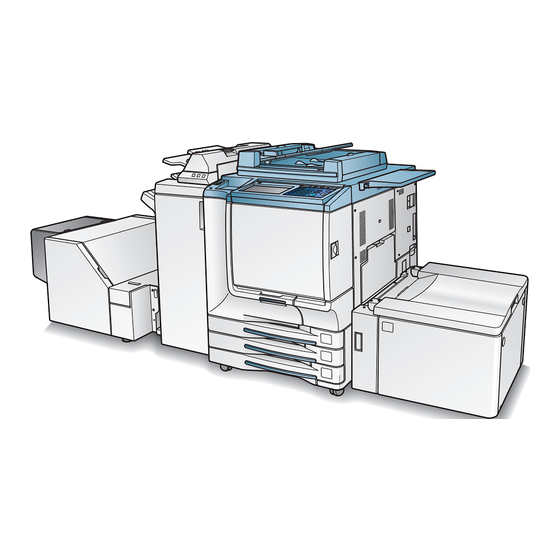
PK-507/PK-508 Punching kit PI-110 Cover sheet feeder DF-319 Document feeder CV-131 Platen cover Work table Key counter FS-513 Finisher bizhub PRO C500 LT-211 Large main body capacity tray MU-412 Memory unit HD-106 Hard disk drive IP-901Printer controller (Fiery S300 50C-K) -
Page 38: Control Panel Layout
Machine Configuration (continued) Control Panel Layout 19 18 CONTRAST ADJUSTMENT DIAL can be turned to adjust the touch panel contrast. LCD TOUCH SCREEN displays machine and copying status, help information, interactive screens, and touch keys for selecting all functions. CHECK displays a screen showing all settings that are selected for the current job. - Page 39 Machine Configuration (continued) JOB MEMORY displays screens for selecting job store/job recall functions. ACCESS sets the machine to allow copying only when the EKC password is entered. The touch screen of the control panel is covered with glass. Do not drop heavy objects on the glass or put excess weight or pressure on it, otherwise the glass may be scratched or break to cause injury.
-
Page 40: Basic Screen
Machine Configuration (continued) Basic Screen 10 STATUS key 1 Folder keys 9 Memory indicator 6 Original count 2 Word icons 8 Count/Set indicator 5 Reserve job 3 Graphic icons 4 Message area 7 TYPE/SIZE key 19 Colour mode area 17 Paper size area 15 STORE key 20 Output mode keys 18 Copy mode area... - Page 41 Machine Configuration (continued) Original count counts the original pages placed in the document feeder as they are scanned. TYPE/SIZE key appears when the Bypass key is selected, and is touched to specify the type and size of the paper loaded in the Multi-sheet bypass tray. Count/Set indicator indicates the print quantity entered from the control panel keypad, and also indicates the print count on the left of the set count while printing.
-
Page 42: Fs-513/Fs-606 Finisher (With Pk-507/Pk-508 Punching Kit)
Machine Configuration (continued) FS-513/FS-606 Finisher (with PK-507/PK-508 Punching Kit) 4 Secondary 4 Secondary (Sub) tray (Sub) tray 1 Finisher door 1 Finisher door 3 Primary 3 Primary (Main) tray (Main) tray 2 Booklet tray (FS-606 Finisher only) FS-513 Finisher FS-606 Finisher Finisher door opens to the internal Finisher to allow clearing mishandled paper, replenishing staples, and emptying waste basket of Punching kit. - Page 43 Machine Configuration (continued) 4 Sub tray conveyance lever 3 Cover sheet conveyance lever 1 Entrance lever 4 Sub tray conveyance lever 3 Cover sheet 5 Stacker conveyance conveyance lever lever 2 PK-507/PK-508 Punching kit FS-513 Finisher (option) 1 Entrance lever 9 Trash basket (option) 8 Stacker unit...
-
Page 44: Cover Sheet Feeder
Machine Configuration (continued) PI-110 Cover Sheet Feeder 3 Upper tray guide plates 4 Upper tray 2 Upper unit release lever 5 Lower tray 6 Lower tray guide plates 1 Cover sheet feeder control panel Cover sheet feeder control panel controls cover sheet feeder operations. Upper unit release lever can be moved to slide the upper unit of cover sheet feeder for removal of mishandled paper. -
Page 45: Large Capacity Tray
Machine Configuration (continued) LT-211 Large Capacity Tray 5 Paper feed roller 6 LCT paper guides 4 Paper loading button 7 LCT paper guide knobs 8 Rear stopper 2 LCT top door 1 LCT lever 9 Rear stopper knob 10 LCT bottom plate 3 LCT left side door LCT lever can be moved downward to ease removal of mishandled paper. -
Page 46: Trimmer Unit
Machine Configuration (continued) TU-109 Trimmer Unit 7 FS-606 Finisher 6 TU-109A kit 5 Trimmer stacker cover 4 Trimmer unit tray 1 Front-right cover 2 Front door 3 Trimmer stacker Front-right cover opens to allow removal of mishandled paper. Front door opens to allow removal of mishandled paper or waste paper. Trimmer stacker holds sets output in Trimming mode. - Page 47 Machine Configuration (continued) 1 Trimmer unit knob 3 Trimmer pressure 2 Wast basket release lever Trimmer unit knob can be turned to ease removal of mishandled paper. Waste basket holds waste paper cut off from the booklets. Trimmer pressure release lever opens to allow removal of mishandled paper. 2-15...
-
Page 48: Turning On The Power Switch
Turning On the Power Switch To Turn On the Power Turn ON the power switch. The power switch is located on the left side of the control panel. The main power switch is located on the upper-left side of the internal main body. - Page 49 Turning On the Power Switch (continued) You can set reserve jobs while the machine is warming up. Touch the LCD screen to change the Warm-up Screen to the Basic Screen, then check that the message “Ready to copy reserve” is displayed on the Basic Screen. See p.
-
Page 50: To Turn Off The Power
Turning On the Power Switch (continued) To Turn Off the Power Turn OFF the power switch. The power switch is located on the left side of the control panel. The touch screen and all the LEDs on the control panel will go out. Be sure not to use the main power switch in usual operation. -
Page 51: Reducing The Power In Standby Mode (Auto Low Power)
Turning On the Power Switch (continued) Reducing the Power in Standby Mode (Auto Low Power) This function automatically lowers the power after a specified period (initially 15 minutes) of copier inactivity. The LCD screen will go off. The Auto Low Power function can be set to 5 minutes/ 10 minutes/ 15 minutes/ 30 minutes/ 60 minutes/ 90 minutes/ 120 minutes/ 240 minutes in the Key Operator mode. -
Page 52: Shutting Off / Reducing The Power Manually
Turning On the Power Switch (continued) Shutting Off / Reducing the Power Manually Follow the procedure below to shut off the power manually. The machine is initially set to activate the Manual Shut-Off function. The Manual Low Power can be selected in the Key Operator setting. See p. 14-37 to p. -
Page 53: Entering An Ekc Password (Ekc)
Turning On the Power Switch (continued) Entering an EKC Password (EKC) The Electronic Key Counter (EKC) allows the Key Operator to monitor all copying activities by controlling EKC password accounts. Copy quantity limits for specific accounts can be set. The EKC is not factory-set. An EKC password is required only when the EKC is activated, a User Password is assigned, and “Enter E.K.C. -
Page 54: Loading Paper
Loading Paper A paper indicator is shown on each tray key of the Basic Screen to indicate the paper level (six levels are provided: ) of the tray. (The Multi-sheet bypass tray displays only “ ” when paper in the tray becomes empty.) When paper supply in a tray becomes low, the indicator “... -
Page 55: Loading Paper In Tray 1 ,2, And 3
Loading Paper (continued) Loading Paper in Tray 1 ,2, and 3 Withdraw tray 1, 2, or 3, and open the paper feed roller. Do not withdraw the tray forcibly; otherwise you may be injured. Withdraw the tray completely until the green line appears at the left rear side of the tray. - Page 56 Loading Paper (continued) Be sure to fix the side guide plate in position according to the size indication on the tray bottom plate so that the machine can detect the correct paper size. Adjust the position of the rear stopper. To slide the rear stopper to the right, hold it at the upper part and slide it while pressing down slightly.
- Page 57 Loading Paper (continued) When paper is seated properly, close the paper feed roller. Gently push in the tray until it locks into place. “ ” on the tray key will change to “ ”. The indicator Do not clam the tray into the main body; otherwise machine trouble may be caused.
-
Page 58: Loading Paper In Multi-Sheet Bypass Tray
Loading Paper (continued) Loading Paper in Multi-Sheet Bypass Tray When using the Multi-sheet bypass tray, specify the paper type to be loaded on the tray at the same time. See p. 3-18 to p. 3-21 for details. Open the Multi-sheet bypass tray located on the right side of the copier. -
Page 59: Loading Paper In Lct (Lt-211)
Loading Paper (continued) Loading Paper in LCT (LT-211) Be sure to load only the paper type and weight set for the LCT. Key Operator can change this setting. See p. 14-21 to p. 14-22. Open the LCT top door. The LCT bottom plate will go up. Without the power turned on, the LCT bottom plate will not function. - Page 60 Loading Paper (continued) (2) Move the upper part of the two LCT paper guides to the appropriate positions according to the size indication, then turn the LCT paper guide knobs (two for each) clockwise to fix the guides. (3) Move the position of the rear stopper to the appropriate positions according to the size indication on the bottom plate, then turn the two rear stopper knobs clockwise to fix the rear stopper.
- Page 61 Loading Paper (continued) Repeat the step 3 until the bottom plate will not go down any more. • Do not load above the limit indicated on the LCT paper guides. • Be sure that the rear stopper is correctly positioned according to the paper size to be loaded;...
-
Page 62: Loading Tabbed Sheets In Tray 1, 2, Or 3
Loading Paper (continued) Loading Tabbed Sheets in Tray 1, 2, or 3 When TAB is displayed on the tray key of the Basic Screen, follow the procedure below to supply the tray with tabbed sheets. The tray paper type can be specified in the Key Operator setting. For details, see p. -
Page 63: Loading Tabbed Sheets In Lct (Lt-211)
Loading Paper (continued) Loading Tabbed Sheets in LCT (LT-211) Rear Example: 3 Tabbed sheets loaded in position for one finished set. 1st TAB 1st TAB Section 1 2nd TAB Introduction Section 1 Introduction Printed 2nd TAB side 3rd TAB Front 3rd TAB ONE FINISHED SET Example: 9 Tabbed sheets loaded in position for 3 finished sets. -
Page 64: Loading Tabbed Sheets In Multi-Sheet Bypass Tray
Loading Paper (continued) Loading Tabbed Sheets in Multi-Sheet Bypass Tray Example: 3 Tabbed sheets loaded in position for one finished set. Rear 1st TAB 1st TAB Section 1 2nd TAB Introduction Section 1 2nd TAB Introduction 3rd TAB Printed side 3rd TAB Front ONE FINISHED SET... - Page 65 Section 3: Copying Operations How to Make a Basic Copy Selecting Colour Mode ............. 3-2 Positioning Originals............3-4 Setting Print Quantity ............. 3-10 Setting Job During Warm-up .......... 3-11 To Stop Scanning/Printing ..........3-13 Selecting Paper Size ............3-14 Copying Using Special Paper (Multi-Sheet Bypass Tray) ... 3-18 Selecting Magnification Ratio (Lens Mode) ....
-
Page 66: Selecting Colour Mode
Selecting Colour Mode The following four colour modes are available: AUTO mode detects whether the scanned original is coloured or black-and-white image, and automatically selects either FULL COLOUR mode or BLACK mode for copying. FULL COLOUR mode makes full-coloured copies whether the original image is coloured or not. - Page 67 Selecting Colour Mode (continued) FULL COLOUR is already highlighted when the initial settings are restored. The initial settings may have been altered by Key Operator. See p. 14-10 for details. Selecting SINGLE COLOUR will display the popup menu to specify a colour.
-
Page 68: Positioning Originals
Positioning Originals Set the originals in the RADF or on the platen glass to copy. Positioning Originals in RADF The document feeder (RADF) automatically feeds up to 100 originals directly to the platen area, starting with the top sheet. The RADF should only be used for unstapled, smooth, flat originals. - Page 69 Positioning Originals (continued) Adjust paper guides.
- Page 70 Positioning Originals (continued) Positioning originals in Mixed original mode Mixed size originals can be copied together from the document feeder. • To use the Mixed original mode, see procedure on p. 9-8 to p. 9-9. • See p. 12-10 for available combinations of mixed originals. Arrange originals in order.
- Page 71 Positioning Originals (continued) Positioning originals in Z-Folded original mode Z-Folded original mode detects the folded original size without using the size detection sensor of the RADF. • To use the Z-Folded original mode, see procedure on p. 9-10 to p. 9-11. •...
-
Page 72: Positioning Original On Platen Glass
Positioning Originals (continued) Positioning Original on Platen Glass Use the platen glass when originals are not suitable for use with the document feeder, e.g., when size is incompatible, or when originals are folded, stapled, torn, or in generally poor condition. Raise the document feeder or platen cover. - Page 73 Positioning Originals (continued) Do not place too heavy originals, or do not press strongly when thick original is placed and is under pressure of RADF; otherwise the glass may be broken and you may be injured.
-
Page 74: Setting Print Quantity
Setting Print Quantity This section describes how to set or change print quantity. To Set Print Quantity The copier is initially set to copy the original set in amounts determined by the print quantity setting, then outputs sorted sets. Enter the desired print quantity from the control panel keypad. -
Page 75: Setting Job During Warm-Up
Setting Job During Warm-up While the copier is warming up after power is turned on, select copy conditions and start scanning so that the copier may start printing immediately when the copier engine is ready. Turn on the power switch of the machine. Seven types of Warm-up Screens display in succession. - Page 76 Setting Job During Warm-up (continued) Press [START]. The original for the job will be scanned, and the highlighted FREE JOB folder key will change to SCAN JOB. When scanning is completed, SCAN JOB will change to RESERVE JOB, and the next FREE JOB becomes active. If setting more than one reserve job, touch the next FREE JOB to highlight it.
-
Page 77: To Stop Scanning/Printing
To Stop Scanning/Printing Follow the procedure below to stop scanning or printing. Touch to highlight SCAN JOB or PRINT JOB to be suspended. Press [STOP]. The current machine operation of the selected job will be suspended. If wrong job is suspended, touch CONTINUE on the popup menu immediately, select the correct job, then press [STOP] to suspend it. -
Page 78: Selecting Paper Size
Selecting Paper Size To select an appropriate paper size for getting your desired copy result, use APS (Automatic Paper Selection), or select paper size manually on the touch screen, as required. To Select Paper Size Automatically (APS) APS detects the size of originals placed on the RADF or platen glass and automatically selects and feeds copy paper of the same size, or selects an appropriate size according to the magnification ratio selected. - Page 79 Selecting Paper Size (continued) • If the appropriate copy paper is not loaded in any tray, no copying will be performed, and a message will prompt you to load the appropriate paper. • Copy result may not be satisfactory due to the Rotation function. In this case, turn the function OFF manually.
-
Page 80: To Specify Desired Paper Size (Ams)
Selecting Paper Size (continued) To Specify Desired Paper Size (AMS) When a paper size is specified on the touch screen, an appropriate reduction or enlargement ratio will be selected automatically according to the original size detected from the RADF or the platen glass. Wide paper size can be specified when AMS is in use. - Page 81 Selecting Paper Size (continued) • Copy result may not be satisfactory due to the Rotation function. In this case, turn the function OFF manually. See. p. 8-4. • See the table below for the relation of original size, copy paper size, and magnification ratio automatically selected.
-
Page 82: Copying Using Special Paper (Multi-Sheet Bypass Tray)
Copying Using Special Paper (Multi-Sheet Bypass Tray) Use the Multi-sheet bypass tray to copy using special (non-standard) paper. Select the special paper type and weight from the selections previously specified by the Key Operator, then select the size to be loaded on the Multi-sheet bypass tray, as described below. - Page 83 Copying Using Special Paper (Multi-Sheet Bypass Tray) (continued) Select the paper type and weight. To select the paper type and weight: Select the desired one out of the six keys on the menu to highlight it. • If the desired paper type and weight cannot be found on the popup menu, specify it in the Key Operator mode.
- Page 84 Copying Using Special Paper (Multi-Sheet Bypass Tray) (continued) To select the STD size (special): Touch STD size (special) to display the popup menu, then use arrow keys to scroll to the desired size. To select the Non STD size Touch Non STD size to display the popup menu, touch the vertical or horizontal size key to highlight it, then use the keypad on the popup menu to enter the vertical/horizontal size, or use arrows to scroll to that number.
- Page 85 Copying Using Special Paper (Multi-Sheet Bypass Tray) (continued) Touch Wide size paper to display the popup menu, use arrow keys to scroll to the desired wide size, then touch Lead edge or Rear edge to select the paper dimensions corresponding to the wide paper sizes entered. Touch Input size to display the Input Size popup menu, touch the vertical or horizontal size key to highlight it, then use the keypad on the popup menu to enter the vertical/horizontal size, or use arrow keys to scroll to that...
-
Page 86: Selecting Magnification Ratio (Lens Mode)
Selecting Magnification Ratio (Lens Mode) When the copier is turned ON, the magnification ratio is set to 1.000 (100%) automatically on the Basic Screen. Follow each procedure described in this section to select the desired magnification ratio. To Copy in 1.000 Magnification Mode Follow this procedure to make a 100% copy of the original image. -
Page 87: To Change Magnification Ratio (Fixed Magnification / Zoom Mode)
Selecting Magnification Ratio (Lens Mode) (continued) To Change Magnification Ratio (Fixed Magnification / Zoom Mode) Use the 8 preset ratios (0.500, 0.707, 0.816, 0.866, 1.154, 1.224, 1.414, 2.000) and 3 user preset ratios to increase or decrease magnification in fixed amounts, or use the Zoom mode to reduce or enlarge the copied original image in 0.1% (0.001) increments. - Page 88 Selecting Magnification Ratio (Lens Mode) (continued) To specify a zoom ratio: Touch the Vertical/Horizontal zoom key in the ZOOM area to highlight it. Use the keypad on the popup menu to enter the desired magnification ratio, then touch OK. The selected ratio will be displayed on the Basic Screen. •...
-
Page 89: Making Double-Sided Copies (1A2, 2A2)
Making Double-Sided Copies (1a2, 2a2) The Basic Screen is initially set to 1a1 copy mode to make single-sided copies from single-sided originals. Follow the procedure below to make double-sided copies from the originals scanned from the document feeder or from the platen glass. Using RADF Select the copy mode according to the original type (single-sided or double-sided). - Page 90 Making Double-Sided Copies (1a2, 2a2) (continued) Check and specify the original set direction and binding mode. The Original direction icon is located at the upper left corner of the Basic Screen. To change the original set direction, touch SPECIAL ORIGINAL on the Basic Screen to display the Special Original popup menu, then touch the desired original direction key to highlight it.
- Page 91 Making Double-Sided Copies (1a2, 2a2) (continued) Selecting TOP BIND will make copies upside down on the reverse side, while RIGHT&LEFT BIND copies normally. Copies Binding mode Touch OK to return to the Basic Screen. Select additional copy conditions, as desired. Some incompatible conditions may automatically release the selected copy mode.
-
Page 92: Using Platen Glass
Making Double-Sided Copies (1a2, 2a2) (continued) Using Platen Glass Use the platen glass to scan originals unsuitable for the document feeder. Specification for Double-Sided Copying Using Platen Glass ❒ Use the Platen store mode. ❒ See p. 12-9 for the information on unsuitable RADF originals. ❒... - Page 93 Making Double-Sided Copies (1a2, 2a2) (continued) Selecting TOP BIND will make copies upside down on the reverse side, while RIGHT&LEFT BIND copies normally. Copies Binding mode Touch OK to return to the Basic Screen. Position original FACE DOWN on the platen glass according to the original direction, then close the document feeder or platen cover.
- Page 94 Making Double-Sided Copies (1a2, 2a2) (continued) DO NOT press [AUTO RESET] at this point, otherwise the platen mode will be released to disable the copier from scanning the original placed on the platen glass. Select additional copy conditions, as desired. Some incompatible conditions may automatically release the selected copy mode.
-
Page 95: Making Single-Sided Copies From Double-Sided Originals (2A1)
Making Single-Sided Copies from Double-Sided Originals (2a1) Use RADF and select 2a1 copy mode to make single-sided copies from double- sided originals. Specification for Single-Sided Copying from Double-Sided Originals ❒ See p. 12-9 for the information on unsuitable RADF originals. ❒... - Page 96 Making Single-Sided Copies from Double-Sided Originals (2a1) (continued) Check and specify the original set direction and binding mode. The Original direction icon is located at the upper left corner of the Basic Screen. To change the original set direction, touch SPECIAL ORIGINAL on the Basic Screen to display the Special Original popup menu, then touch the desired original direction key to highlight it.
-
Page 97: To Scan Originals Into Memory (Store Mode)
To Scan Originals into Memory (Store Mode) Store mode allows you to scan all the originals first, then to start a continuous printing job. Use RADF store mode to scan a large amount of originals. Use Platen store mode for originals that cannot be fed through the document feeder due to thickness, size or condition. - Page 98 To Scan Originals into Memory (Store Mode) (continued) Using RADF: Position originals with page one FACE UP. Up to 100 originals can be loaded. If the number of originals exceeds 100, divide them into blocks not exceeding 100 sheets and load them beginning with the block with the first page.
-
Page 99: To Set Next Copying Job (Reserve)
To Set Next Copying Job (Reserve) The Reserve function allows you to set up a new job while a current job is in process. When the current job is finished, the Reserve job starts printing immediately. Specifications for Reserve ❒ Job settings: Max. 10 (current job plus 9 reserve jobs) ❒... - Page 100 To Set Next Copying Job (Reserve) (continued) Position original(s) after completing the scan for the current job. See p. 3-4 to p. 3-9 for details on positioning originals. To cancel the reserve job, touch STATUS on the Basic Screen to display the Job Status Screen.
- Page 101 To Set Next Copying Job (Reserve) (continued) To set the seventh copying job, touch the active FREE JOB key at the far right to scroll to the next reserve setting screen. The number of reserve jobs including current job will be indicated in the middle of the message area.
-
Page 102: To Check/Control Jobs In Progress (Job Status Screen)
To Check/Control Jobs in Progress (Job Status Screen) The Job Status Screen allows you to perform the following functions. • Confirm machine status • Change order of reserve job • Delete reserve job • View previous job list • View noncomplete job list Not only the copy reserve jobs but the print jobs made in Printer mode can also be checked and controlled on this screen. - Page 103 To Check/Control Jobs in Progress (Job Status Screen) (continued) To check user name (print jobs only): Touch USER NAME CHECK to display the User Name Check Screen. Check the user name indicated on the right side of the job number and operation mode.
- Page 104 To Check/Control Jobs in Progress (Job Status Screen) (continued) Contents of Job Status Screen NO. : Displays the No. (01-99) for each job assigned to the machine. MODE: Displays the machine’s current mode of operation. Three modes are listed below. COPIER PRINTER SCANNER...
-
Page 105: Output Mode For Machine Without Finisher
Output Mode for Machine without Finisher This section describes the output modes for a copier without the Finisher. The Non-sort mode is initially selected. 1 Non-sort mode copies the original set in amounts determined by the print quantity setting, then outputs sorted sets normally. 2 Rotation sort mode rotates every other sorted sets by 90°... - Page 106 Output Mode for Machine without Finisher (continued) Specification for Output Modes without Finisher ❒ Incompatible with Group mode: Proof Copy, Sheet/Cover Insertion, Chapter, Combination, Booklet, Image Insert, Program Job, Repeat, AUTO Layout, Non-Image Area Erase, Stamp (Numbering) ❒ Incompatible with Rotation Group mode: Proof Copy, Mixed Original, Z-Folded Original, Non STD Size (FULL AREA), Sheet/Cover Insertion, Chapter, Combination, Booklet, Image Insert, Dual Page, Program Job, Repeat, AUTO Layout, Non-Image Area Erase, Stamp (Numbering), Overlay...
- Page 107 Output Mode for Machine without Finisher (continued) Touch OK on the Output Mode popup menu. The Basic Screen will be restored with the output icon indicating the Output mode currently selected. Touch CANCEL on the Output Mode popup menu to restore the previous setting.
- Page 108 Output Mode for Machine without Finisher (continued) Output Icons on the Basic Screen Face Down Non-sort Rotation sort Group Rotation group Face Up Non-sort Rotation sort Group Rotation group 3-44...
-
Page 109: Output Mode For Machine With Finisher
Output Mode for Machine with Finisher Finisher FS-513/FS-606 is equipped with a primary (main) and a secondary (sub) exit trays. Without using any optional equipment, each exit tray provides the output modes as described below. When the Memory switch No. 58 "Finisher operating (Thick)" of the Key Operator mode is set to prefer image quality, copy speed may become maximum one-sixth lower depending upon the paper type or specified output mode. - Page 110 Output Mode for Machine with Finisher (continued) Secondary (Sub) Tray: 1 Face down non-sort exit outputs simplex copies and odd numbered duplex copies face down, without offsetting the sorted sets. 2 Face down group exit outputs multiple copies of each original face down, without offsetting the grouped sets upon exit.
- Page 111 Output Mode for Machine with Finisher (continued) ❒ Incompatible with Group using Secondary (sub) tray: 1a2 or 2a2 mode using platen glass (unless Platen store mode is used), Proof Copy, Fold, Stitch & Fold, Three-Fold, Trimming, Punch, Cover sheet feeding, Sheet/Cover Insertion, Chapter, Combination, Booklet, Image Insert, Repeat ❒...
- Page 112 Output Mode for Machine with Finisher (continued) To set Staple-sort mode: (1) Touch STAPLE on the Basic Screen to highlight it. The staple position icon will be displayed in the output icon area. To change the staple position, proceed to the next step. Proceed to step (3), if the present setting is desired.
- Page 113 Output Mode for Machine with Finisher (continued) (3) Check the original set direction with the Original direction icon at the upper left corner of the Basic Screen. To change the original set direction, touch SPECIAL ORIGINAL on the Basic Screen to display the Special Original popup menu, touch the desired original set direction key, then touch OK to return to the Basic Screen.
- Page 114 Output Mode for Machine with Finisher (continued) See p. 3-10 for details on setting print quantity. Position original(s). See p. 3-4 to p. 3-9 for details on positioning originals. Press [START]. Press [STOP] to suspend the scanning or printing job. See p. 3-13 for details. Finisher primary (main) tray of Finisher FS-513/FS-606 gradually goes down while printed materials output.
- Page 115 Output Mode for Machine with Finisher (continued) Primary (Main) tray: Staple-Sort Left 1 posi. Right 1 posi. Left 2 posi. Up 2 posi. Secondary (Sub) tray: Face down Secondary (Sub) tray: Face up Non-sort Group Non-sort Group 3-51...
-
Page 116: Selecting Binding Mode
Selecting Binding Mode When copying in 1a2 or 2a2 mode, specify the binding mode on the Output Mode popup menu to obtain the desired copy result. Right & Left bind: Normal duplex copies Top bind: Duplex copies arranged upside down on the reverse side The same binding mode is initially selected as the original binding mode specified on the Special Original popup menu. - Page 117 Section 4: Helpful Functions How to Use Helpful Functions Making Sample Copy (Proof Copy) ........4-2 Checking Feature Selections / Proof Copying (Check Mode) ..4-4 Interrupt Copying .............. 4-8 Storing Job Conditions (Job Memory: Job Store)... 4-11 Recalling Stored Job Settings (Job Memory: Job Recall)... 4-14 Recalling Previous Job Settings ........
-
Page 118: Making Sample Copy (Proof Copy)
Making Sample Copy (Proof Copy) Use Proof copy to produce a sample of the copied set before making multiple copies. This is a convenient and cost effective way of viewing the results of the following copying selections. • Copying conditions using Store mode •... - Page 119 Making Sample Copy (Proof Copy) (continued) If the copy result is satisfactory, proceed to step 5. If any setting changes are required, refer to p. 4-6 under the next heading. Repeat proof copying until the copy result becomes satisfactory. Change the print quantity, as required. Proof copy can be performed as needed, until the print quantity amount on the Basic Screen reaches zero.
-
Page 120: Checking Feature Selections / Proof Copying (Check Mode)
Checking Feature Selections / Proof Copying (Check Mode) Use the Check mode to confirm copying selections before starting print operation. In this mode, use Proof copy to produce a sample of the copied set before making multiple copies. This is a convenient and cost effective way of viewing the results of the following copying selections. - Page 121 Checking Feature Selections / Proof Copying (Check Mode) (continued) The Check Screen will be displayed. Exclusive Paper Title Check Screen Tray Setting Check Screen Touch the lower arrow key to scroll to the next screen in order as shown above. Touching the upper arrow key will resume the previous screen. Touch TrayConfirm to display the Tray Setting Check Screen.
- Page 122 Checking Feature Selections / Proof Copying (Check Mode) (continued) To change the settings: Touch the desired copying condition key on the Check Screen to highlight it. Any key that cannot be highlighted indicates that the copying condition cannot be changed from the Check Screen. Touch CHANGE SETTING.
- Page 123 Checking Feature Selections / Proof Copying (Check Mode) (continued) Press [PROOF COPY] on the control panel or touch PROOF COPY on the Check Screen. A sample copy will be output. • Press [STOP] to suspend the proof copying. In this case, the scanned image data will not be deleted from memory.
-
Page 124: Interrupt Copying
Interrupt Copying Use the Interrupt mode to interrupt copying in progress to perform a simple job. When interrupt copying is completed, the settings for the initial job restore automatically and the Basic Screen displays. Interrupt copying is available when the copier is performing the following operations: •... - Page 125 Interrupt Copying (continued) In Reserve mode, pressing [INTERRUPT] before the copier finishes scanning the reserve job originals clears the settings selected for the reserve job. For details of Reserve mode, see p. 3-35 to p. 3-37. Set copy conditions, as desired. The initial settings in Interrupt mode are as follows.
- Page 126 Interrupt Copying (continued) For particular jobs in progress, copying will cease only after certain phases of the immediate operation are completed, as indicated by the [INTERRUPT] LED conditions described below. • Collectively printing image stored in memory The LED blinks until one set of the current job is printed. Then the LED remains steady for the temporary job performed in Interrupt mode.
-
Page 127: Storing Job Conditions (Job Memory: Job Store)
Storing Job Conditions (Job Memory: Job Store) Use Job Store to store up to 30 frequently used copy job settings, which can be recalled at any time. The stored jobs can be given alphabetical names. Specifications for Job Memory ❒ All copying functions can be selected. ❒... - Page 128 Storing Job Conditions (Job Memory: Job Store) (continued) Review the settings on the Job Store Check Screen. Touch the lower arrow key to scroll to the following pages. Check that the selections made in step 1 are correctly entered. If any correction is required, touch CANCEL to return to the Basic Screen. Make new selections, then restart the Job Store operation from step 2.
- Page 129 Storing Job Conditions (Job Memory: Job Store) (continued) If you wish to cancel the job number selection, touch CANCEL to restore the Basic Screen, which displays the settings made in step 1. If you wish to cancel the settings, press [AUTO RESET]. Touch OK.
-
Page 130: Recalling Stored Job Settings (Job Memory: Job Recall)
Recalling Stored Job Settings (Job Memory: Job Recall) Use Job Recall to recall jobs that are already stored in Job Memory. Press [JOB MEMORY] on the control panel. The Job No. Selection Screen will be displayed. Touch to highlight a job number key to select a job you want to recall. -
Page 131: Recalling Previous Job Settings
Recalling Previous Job Settings Follow the procedure below to copy with a previous job’s settings. • Only the last-completed output job settings can be recalled as the previous job settings. Non-complete job or reserve job settings cannot be recalled, even if the setting operations have been made last. •... -
Page 132: Displaying Screen For Operation Guide (Help Mode)
Displaying Screen for Operation Guide (Help Mode) The Help Screen provides you with the information about the current screen mode and about setting procedures. Help mode can be accessed from any screen except Job Memory and Key Operator Screens. Help mode provides two types of Help Screens according to the current screen mode: 1 Help Screen accessed from Basic Screen 2 Help Screen accessed from screens other than Basic Screen... - Page 133 Displaying Screen for Operation Guide (Help Mode) (continued) • PANEL CONTRAST displays the screen to adjust the contrast of the LCD panel. • Toner Recovery box provides information on exchanging the toner recovery box. • FOR ASSISTANCE displays the extension number of the Key Operator. •...
-
Page 134: To Display Help Screen From Other Screens
Displaying Screen for Operation Guide (Help Mode) (continued) To Display Help Screen from Other Screens While in any screen other than the Basic Screen, press [HELP]. The Help Screen displays to provide the information about the current screen mode and setting procedures. Touch EXIT. -
Page 135: Troubleshooting
Section 5: Troubleshooting How to Handle Machine Troubles When “Call for Service” Message Is Displayed ....5-2 Clearing Mishandled Paper ..........5-4 When “JAM” Appears on Folder Key (Or Arrow Key Flashes) ..5-6 When “ADD PAPER” Appears on Folder Key (Or Arrow Key Flashes) .. 5-8 When “Memory Full”... -
Page 136: When "Call For Service" Message Is Displayed
When “Call for Service” Message Is Displayed A “Call for Service” message indicates a machine condition that requires the attention of your service representative. The Call for Service Screen usually displays the telephone and facsimile numbers of your service representative. When the Call for Service Screen is displayed, be sure to contact your service representative immediately by following the procedure below. -
Page 137: Limited Use Of The Copier In Trouble
When “Call for Service” Message Is Displayed (continued) Unplug the machine. Contact your service representative and report the condition and code No. Limited Use of the Copier in Trouble If the message shown below is displayed on the Call for Service Screen, you may continue operating the copier on a limited function basis and utilize the trays and ADU that are not affected by the trouble. -
Page 138: Clearing Mishandled Paper
Clearing Mishandled Paper When a paper misfeed occurs, the copier stops making copies and mishandled paper codes display on the screen to indicate misfeed area(s). Copying operation cannot be continued until all the misfeed locations are cleared. Graphic Illustration key Touch to display the subsequent screens for the disposal action. - Page 139 Clearing Mishandled Paper (continued) The drum unit generates high voltage. To avoid bodily electrical shock, NEVER TOUCH the area. The internal fixing unit is very hot. To avoid getting burned, DO NOT TOUCH. Be careful of removing staples stuck inside the machine so as not to get injured.
-
Page 140: When "Jam" Appears On Folder Key (Or Arrow Key Flashes)
When “JAM” Appears on Folder Key (Or Arrow Key Flashes) If a misfeed occurs with the print/scan job in progress while you are setting a reserve job, SCAN or PRINT JOB folder key on the Basic Screen will change to flashing JAM JOB. - Page 141 When “JAM” Appears on Folder Key (Or Arrow Key Flashes) (continued) Touch Graphic Illustration. The screen illustrating the method for the disposal action will be displayed. See p. 5-4 to p. 5-5 for details on clearing procedure. Follow the procedure on the screen to remove misfed paper. When all procedures are completed, the Basic Screen will be restored.
-
Page 142: When "Add Paper" Appears On Folder Key (Or Arrow Key Flashes)
When “ADD PAPER” Appears on Folder Key (Or Arrow Key Flashes) If the paper supply for a print job in progress becomes depleted while you are setting a reserve job, PRINT JOB on the Basic Screen will change to flashing ADD PAPER. When more than four jobs have been specified and the folder key of the print job in trouble is not currently displayed on the screen, the arrow key to scroll to that job will flash. -
Page 143: When "Memory Full" Message Is Displayed (Memory Overflow)
When “Memory Full” Message Is Displayed (Memory Overflow) In certain modes, this printer/copier uses memory to make operations convenient and smooth flowing. Occasional memory overflow may occur if the installed memory is inadequate for the copy conditions selected. To handle the Memory overflow condition while performing a job, take the appropriate action described below. -
Page 144: Memory Overflow In Reserve Job
When “Memory Full” Message Is Displayed (Memory Overflow) (continued) Memory Overflow in Reserve Job When memory overflow occurs during the reserve operation, CONTINUE also appears on the active screen. In this case, the machine will not stop until all the jobs on standby for printing are completed. -
Page 145: When Power Off/On Screen Is Displayed
When Power OFF/ON Screen Is Displayed When any trouble affects the electrical signal of the copier, the Power OFF/ON Screen will be displayed. Follow the procedure below to turn the machine power off then on. Turn OFF the power switch. Wait about 10 seconds. -
Page 146: Troubleshooting Tips
Troubleshooting Tips COPIER DOES NOT OPERATE WHEN POWER SWITCH IS ON Fully insert paper trays. Close RADF. Close Front doors of main body. Close Finisher door. Check to be sure main power switch is ON. Check to be sure power plug is firmly inserted in electrical socket. COPY IMAGE IS TOO LIGHT Manually adjust copy density to darker density. - Page 147 Troubleshooting Tips (continued) COPYING DOES NOT RESUME AFTER MISHANDLED PAPER IS REMOVED Check copier diagram on touch screen for additional indications of mishandled paper. COPY QUALITY IS POOR Check paper for dampness, and replace it if necessary. THE ORIGINAL PAPER IS MISHANDLED OR SKEWED IN THE DOCUMENT FEEDER Originals should conform to the recommended size and weight.
- Page 148 Troubleshooting Tips (continued) “PLEASE CHECK ORIGINAL” This message displays when the copier detects a non-standard paper size on the platen glass. Select paper size and press [START]. 1.000 magnification will be selected automatically. If this message continues to display after selecting paper size, select 1.000 magnification, even if it is already indicated, then press [START].
-
Page 149: Section 6: Machine Specifications
Section 6: Machine Specifications Main Body & Option Specifications Main Body Specifications ..........6-2 Option Specifications............6-4... -
Page 150: Main Body Specifications
Main Body Specifications Main Body Name: bizhub PRO C500 Type: Console type Transfer method: Indirect electrostatic method Platen glass: Fixed Light-sensitive unit: Light source: Xenon lamp Developing method: Dry, 2-component magnetic brush developing Fixing method: Heat roller Density adjustment: Automatic and manual (9 steps) Magnification ratio: 1.0 %... - Page 151 Main Body Specifications (continued) Power: AC 230 V / 50 Hz (This equipment selects the correct voltage automatically.) Power consumption: 3.4 KW max. (with option) Sound power level: 78 dB max. (with option) Weight: Approx. 313 kg (main body) + 1.6 kg w/Platen cover (CV-131) + 14.5 kg w/RADF + 56 kg w/Finisher (FS-513) + 66 kg w/Finisher (FS-606)
-
Page 152: Option Specifications
Option Specifications RADF (DF-319) Function: Feeds 1- and 2-sided originals automatically Type of original: 35 g/m ~ 200 g/m in Simplex mode (Use Thin mode of THICKNESS/SPECIAL ORIGINAL for 35 g/m ~ 49 g/m paper) 50 g/m ~ 200 g/m in Duplex mode (Use Thick mode of THICKNESS/SPECIAL ORIGINAL for 129 g/m... -
Page 153: Cover Sheet Feeder
Option Specifications (continued) PI-110 Cover Sheet Feeder Function: Paper feed into Finisher FS-513/FS-606 Configuration: 2 trays (upper/lower) Types of paper: 50 to 256 g/m paper Paper sizes: Upper tray A4, A4R, B5, B5R, A5, 8.5"x11", 8.5"x11"R, 5.5"x8.5" Lower tray A3, B4, F4, A4, A4R, B5, B5R, A5, 11"x17", 8.5"x14", 8.5"x11", 8.5"x11"R, 5.5"x8.5", and those Wide sizes (max. -
Page 154: Pk-507/Pk-508 Punching Kit
Option Specifications (continued) PK-507/PK-508 Punching Kit Function: Punching file holes in copies Number of punch holes: Hole diameter: 6.5 mm 0.5 mm ± Hole pitch: 80 mm 0.5 mm ± Paper sizes: A3, B4, A4, B5, 11"x17", 8.5"x11" Types of paper: 50 g/m ~ 128 g/m paper... - Page 155 Advanced...
- Page 157 Section 7: Colour Image Adjustment About Colours..............7-2 Colour Copy Quality ............7-4 Selecting Density Level and Whitening the Background(Copy Density) ..7-15 Changing Colours Using RGB and HSB Values (Colour Adjustment) . 7-19 Changing Colours Using CMYK Value (Colour Balance Adjustment).. 7-24 Selecting Line Screen, Dot Screen, or High Compression (Screen Setting) 7-26 Adjusting Sharpness and Contrast / Selecting Gloss Mode ..
-
Page 158: About Colours
About Colours RGB and CMYK Models Have you ever wondered why the world surrounding us appears coloured to our eyes? Light is electromagnetic waves with wavelengths between about 380 - 780 nm, also called visible rays. The wavelengths of visible rays can be separated into the rainbow colours violet, indigo, blue, green, yellow, orange, and red, from the shortest wavelength in order. -
Page 159: Hsb Model
About Colours (continued) HSB Model This model is based on the human perception of colour. When our eyes perceive colours in objects, we receive the information not only on the colour itself (reddish, bluish, etc.) but the brightness (rather bright, dark, etc.) and the purity (vivid, dull, etc.) of the colour. -
Page 160: Colour Copy Quality
Colour Copy Quality Modifying Colours As mentioned above, colours can be reproduced by mixing four pigments, the three primary colours cyan (C), magenta (M), yellow (Y), and black (K). To enhance the copy quality, this machine allows you to modify colours by means of the three attributes of colour based upon the human eye and perception. - Page 161 Colour Copy Quality (continued) Adjust the hue, saturation, and brightness. Original –4 Saturation –4...
- Page 162 Colour Copy Quality (continued) Brightness –4 The hue adjustment leads the colour of the image to another colour adjacent in the colour circle of red (R), yellow (Y), green (G), cyan (C), blue (B), and magenta (M).
- Page 163 Colour Copy Quality (continued) Change the hue by varying the image’s red (R), green (G), and blue (B) individually or mutually. Original –4 Green –4...
- Page 164 Colour Copy Quality (continued) Blue –4...
- Page 165 Colour Copy Quality (continued) Change the hue by varying the image’s cyan (C), magenta (M), yellow (Y), and black (K) individually or mutually. Original Cyan –4 Magenta –4...
- Page 166 Colour Copy Quality (continued) Yellow –4 Black –4 7-10...
-
Page 167: Reproducing Images
Colour Copy Quality (continued) Reproducing Images This machine provides two methods for reproducing images. The Dither (Error Diffusion) method uses small dots (600 dots per inch) to reproduce the image. This method is appropriate for text originals. The Screen method also provides two methods, Line Screen and Dot Screen. The Line Screen uses many halftone lines, like scanning lines of a television, while Dot Screen uses small dots to reproduce the image. -
Page 168: What Is Image Detection
Colour Copy Quality (continued) What Is Image Detection? In many cases, originals include both photo and text. Although the text is normally printed in black, a colour printer inevitably uses not only the black toner but cyan, magenta, and yellow in layers to reproduce the black text. Using the Screen method, the colour printer may add colours in large or bold characters to reproduce the text in the same way as the photo. -
Page 169: Applying Filters
Colour Copy Quality (continued) Applying Filters In addition to the colour adjustment and image reproduction methods, this machine allows you to apply the following filters to improve the copy image quality. Sharpen the outline of the image. (Sharpness) Sharpness Original –4 Increase the contrast of the image. -
Page 170: Improving Colour Copy Quality
Colour Copy Quality (continued) Increase shine on the image. (Gloss Mode) Gloss mode Original Improving Colour Copy Quality To improve the colour copy quality, this machine provides the three types of adjustment methods: Colour adjustment, Selecting the image reproduction method and its adjustment, and other adjustments. -
Page 171: Selecting Density Level And Whitening The Background(Copy Density)
Selecting Density Level and Whitening the Background(Copy Density) Automatic Exposure (AE) operates to detect the density level of the original image while scanning, and automatically selects the appropriate density for the copy. The density to be selected automatically using AE can be adjusted on the machine. - Page 172 Selecting Density Level and Whitening the Background(Copy Density) (continued) Touch COPY DENSITY to display the Copy Density Adjustment Screen. Touch the desired density level key from -1 to -4 to make the copy image lighter, or from +1 to +4 to make it darker. •...
-
Page 173: Setting Density Shift
Selecting Density Level and Whitening the Background(Copy Density) (continued) Setting Density Shift Use this function to shift each of nine density levels to three levels lighter or three levels darker. This function can be set to use in combination with each of the four Original Image modes (Text/Photo, Photo, Text, and Map) in each of the three colour modes (Full colour, Black, and Single colour), therefore twelve sorts of settings are available for the density adjustment. - Page 174 Selecting Density Level and Whitening the Background(Copy Density) (continued) Selected Original image mode: TEXT, Colour mode: SINGLE COLOUR Density Shift (Text Single colour) 3 (0 - 6) Selected Original image mode: MAP, Colour mode: FULL COLOUR Density Shift (Map Full colour) 3 (0 - 6) For details of the Original Image mode, see p.
-
Page 175: Changing Colours Using Rgb And Hsb Values (Colour Adjustment)
Changing Colours Using RGB and HSB Values (Colour Adjustment) Change colour by modifying each value of red (R), green (G), and blue (B), and also adjust the value of hue, saturation, and brightness. Modifying RGB Value Change the colour of the copy image by modifying each value of red (R), green (G), and blue (B). - Page 176 Changing Colours Using RGB and HSB Values (Colour Adjustment) (continued) Touch the desired level key from -1 to -4 to make the colour lighter, or from +1 to +4 to make it deeper. • Touch STD. to select the middle level. •...
-
Page 177: Modifying Hsb Value
Changing Colours Using RGB and HSB Values (Colour Adjustment) (continued) Modifying HSB Value Change the colour of the copy image by making adjustments to Hue, Saturation, and Brightness. Touch IMAGE ADJUST on the Basic Screen. Touch COLOUR ADJUST to display the Colour Adjustment Screen. Make an adjustment to Hue. - Page 178 Changing Colours Using RGB and HSB Values (Colour Adjustment) (continued) Or, touch a key from +1 to +4 to make yellow closer to green, and green closer to cyan (Adjustment goes clockwise in the colour circle.). Touch STD. to select the middle level. Touch OK.
- Page 179 Changing Colours Using RGB and HSB Values (Colour Adjustment) (continued) Touch STD. to select the middle level. Touch OK. The Colour Adjustment Screen will be restored. To resume the previous setting, touch CANCEL. Touch OK. The Basic Screen will be restored, with the IMAGE ADJUST key highlighted. •...
-
Page 180: Changing Colours Using Cmyk Value (Colour Balance Adjustment)
Changing Colours Using CMYK Value (Colour Balance Adjustment) Change the hue by varying the image’s cyan (C), magenta (M), yellow (Y), and black (K) individually or mutually. This adjustment can be made in each density area (shadow, mid tone, or highlight) of the individual colour, or in the whole density area of each colour. - Page 181 Changing Colours Using CMYK Value (Colour Balance Adjustment) (continued) Select the colour and adjustment value. Touch CYAN(C), MAGENTA(M), YELLOW(Y), or BLACK (K) to highlight it. Then, touch the c or d key to display the desired adjustment value from -10 to +10.
-
Page 182: Selecting Line Screen, Dot Screen, Or High Compression (Screen Setting)
Selecting Line Screen, Dot Screen, or High Compression (Screen Setting) This machine provides two methods to reproduce the print image; Line Screen and Dot Screen. The machine selects an appropriate method automatically according to the other copy conditions selected for the job. See p. - Page 183 Selecting Line Screen, Dot Screen, or High Compression (Screen Setting) (continued) Select the desired reproducing method. To select the Line Screen, touch HIGH RESOLUTION or SMOOTH TONE under the LINE SCREEN indication to highlight it. To select the Dot Screen, touch HIGH RESOLUTION or SMOOTH TONE under the DOT SCREEN indication to highlight it.
- Page 184 Selecting Line Screen, Dot Screen, or High Compression (Screen Setting) (continued) Touch OK. The Basic Screen will be restored, with the IMAGE ADJUST key highlighted. • To resume the previous setting, touch CANCEL. • To restore the initial settings, touch RECALL STANDARD. 7-28...
-
Page 185: Adjusting Sharpness And Contrast / Selecting Gloss Mode
Adjusting Sharpness and Contrast / Selecting Gloss Mode In addition to the colour adjustment and reproducing method selection, this machine allows you to apply the following filters to improve the copy image quality. Sharpen the outline of the image. (Sharpness) Increase the contrast of the image. - Page 186 Adjusting Sharpness and Contrast / Selecting Gloss Mode (continued) Select the desired sharpness level. Touch SHARPNESS, then touch the desired level key from -1 to -4 to make the outline softer, or from +1 to +4 to make it sharper. Touch STD.
- Page 187 Adjusting Sharpness and Contrast / Selecting Gloss Mode (continued) To resume the previous setting, touch CANCEL. Select the Gloss Mode. Touch GLOSS MODE to highlight it. Touch OK. The Basic Screen will be restored, with the IMAGE ADJUST key highlighted. •...
-
Page 188: Making Fine Adjustment In Image Detection (Image Judge)
Making Fine Adjustment in Image Detection (Image Judge) Image Detection detects and determines the photo portion and text area of the original when scanned, allowing you to obtain the optimum print result by modifying the standard for detection according to the character size of the text or its proportion in the whole original. - Page 189 Making Fine Adjustment in Image Detection (Image Judge) (continued) Touch IMAGE JUDGE. Make an adjustment to TEXT/PHOTO. Touch the desired level key from -1 to -4 to increase the proportion of photo. Or, touch a key from +1 to +4 to increase the proportion of text. Touch STD.
-
Page 190: Specifying Original Type (Original Image/Type In Special Original)
Specifying Original Type (Original Image/Type in Special Original) The image quality or type of the original may affect the copy result. Use Original Image to improve the image quality by specifying the original image type as follows. • Originals including both text and photo (TEXT/PHOTO) •... - Page 191 Specifying Original Type (Original Image/Type in Special Original) (continued) Touch OK. The Basic Screen will be restored, with the SPECIAL ORIGINAL key highlighted and the selected Original Image icon displayed. • To resume the previous setting, touch CANCEL. • To restore the initial settings, touch RECALL STANDARD. 7-35...
- Page 193 Section 8: Advanced Information How to Use Advanced Functions Programmed Shut-Off (Weekly Timer) ......8-2 Rotation ................8-4 Vertical/Horizontal Zoom Mode ........8-5 Making Folded Booklet (Fold / Stitch & Fold) ....8-8 Punching File Holes in Copies (Punch) ......8-11 Output Three-Folded Copies (Three-Fold) .....
-
Page 194: Programmed Shut-Off (Weekly Timer)
Programmed Shut-Off (Weekly Timer) The Weekly Timer function turns a copier on and off at the time specified by the Key Operator. This function is not factory-set. When the copier is using the Weekly Timer function, the TIMER indicator on the right side of the control panel is lit. IMPORTANT: WHEN THE TIMER INDICATOR IS LIT, THE COPIER WILL TURN OFF AUTOMATICALLY. - Page 195 Programmed Shut-Off (Weekly Timer) (continued) The Timer Interrupt password is not factory set and must be entered by the Key Operator. In the event the Timer Interrupt password has not been entered by the Key Operator, the following message will display instead. Input copy time 0 hour(s) 05 minute(s)
-
Page 196: Rotation
Rotation This function allows you to utilize APS or AMS and copy the original documents onto size A4 or B5, irrespective of the copy paper feeding direction. By default, Rotation requires APS or AMS to function. The Key Operator can set this function ON, or to operate when APS, AMS or reduce functions. -
Page 197: Vertical/Horizontal Zoom Mode
Vertical/Horizontal Zoom Mode Use the Vertical/Horizontal zoom mode to reduce or enlarge vertical and horizontal dimensions, independently. Vertical/Horizontal Zoom Mode Specifications ❒ Vertical/Horizontal zoom range: 0.250~4.000 ❒ Incompatible Conditions: APS, AMS, Reduce & Shift in Image Shift The figure shown below is the sample image using the Vertical/Horizontal zoom. Length: 0.500, Width: 0.500 Length: 0.500, Width: 1.000 Length: 0.500, Width: 2.000... - Page 198 Vertical/Horizontal Zoom Mode (continued) The popup menu for setting a zoom ratio will be displayed. When starting a new copying job, be sure to close the RADF securely, then press [AUTO RESET]. Touch the vertical zoom key on the popup menu to highlight it, then set the vertical zoom ratio.
- Page 199 Vertical/Horizontal Zoom Mode (continued) The figure shown below is the sample image using the Vertical/Horizontal zoom with an original placed slanted on the platen glass. 30° Length: 0.500, Width: 2.000 Length: 2.000, Width: 0.500 30° Length: 0.500, Width: 2.000 Length: 2.000, Width: 0.500...
-
Page 200: Making Folded Booklet (Fold / Stitch & Fold)
Making Folded Booklet (Fold / Stitch & Fold) The Fold and modes are available only when the FS-606 Finisher option Stitch & Fold is installed. When any of these modes is selected, the Booklet feature is automatically selected and indicated on the Application Selection Screen. •... - Page 201 Making Folded Booklet (Fold / Stitch & Fold) (continued) Fold Stitch & Fold 80 g/m 20 sheets max. 19 sheets max. with a thick cover paper 105 g/m or less: 3 sheet max. 105 g/m : 16 sheets max. 15 sheets max. with a thick cover paper Touch OUTPUT MENU on the Basic Screen to display the Output Mode popup menu.
- Page 202 Making Folded Booklet (Fold / Stitch & Fold) (continued) Selecting FOLD or STITCH & FOLD will automatically switch the output tray to Booklet tray. Notice that the arrow pointing from the Main tray shifts to the Booklet tray. When selecting STITCH & FOLD, the machine with the trimmer unit installed selects TRIM automatically.
-
Page 203: Punching File Holes In Copies (Punch)
Punching File Holes in Copies (Punch) The Punch mode is available only when the PK-507/PK-508 Punching kit option is installed on the FS-513/FS-606 finisher. When the Punch mode is selected in combination with any of the Primary (Main) tray output modes, each copied sheet is punched and output to the Primary tray according to the selected output mode. - Page 204 Punching File Holes in Copies (Punch) (continued) Touch MAIN TRAY, if not highlighted. Touch PUNCH to display the Punch Position popup menu. Touch the desired punch position key to highlight it. Touch OK on the Punch Position popup menu to restore the Output Mode popup menu.
- Page 205 Punching File Holes in Copies (Punch) (continued) Specify the original set direction. Touch SPECIAL ORIGINAL on the Basic Screen to display the Special Original popup menu. Touch to select the desired original set direction, then touch OK to return to the Basic Screen.
-
Page 206: Output Three-Folded Copies (Three-Fold)
Output Three-Folded Copies (Three-Fold) The Three-Fold mode is available only when the FS-606 Finisher option is installed. In this mode, the original image is copied on A4R/8.5”x11”R copy paper and output to the Booklet tray of the finisher. Specifications for Three-Fold Mode ❒... - Page 207 Output Three-Folded Copies (Three-Fold) (continued) Touch THREE-FOLD to highlight it. Touch OK on the popup menu to complete the setting and return to the Basic Screen. The THREE-FOLD icon will be displayed in the OUTPUT icon area. Select additional copying features, as required. Touch to highlight the A4R or 8.5”x11”R tray key, if not already highlighted.
-
Page 208: Making Trimmed Booklets (Trimming)
Making Trimmed Booklets (Trimming) The Trimming mode is available only when the TU-109 Trimmer unit option is installed on the FS-606 Finisher. This function can be used with Fold or Stitch & Fold mode to make each copied set folded or stitched & folded, trimmed at the edge that opens the booklet, then output to the Trimmer unit tray. - Page 209 Making Trimmed Booklets (Trimming) (continued) Touch MAIN TRAY, if not highlighted. Select the desired trimming mode. Touch STITCH & FOLD or FOLD, as desired. When selecting FOLD, also touch TRIM to highlight it. When selecting STITCH & FOLD, the machine with the trimmer unit installed selects TRIM automatically.
- Page 210 Making Trimmed Booklets (Trimming) (continued) Enter the desired print quantity from the control panel keypad. See p. 3-10 for details on setting print quantity. Position originals. See p. 3-4 to p. 3-9 for details on positioning originals. When loading originals, heed the following limits on capacity: Fold mode: 12 pages or less for simplex copying 6 pages or less for duplex copying...
-
Page 211: Cover Sheet Feeding
Cover Sheet Feeding The Cover Sheet Feeder (PI-110) is available as an option on the FS-513/FS-606 finisher. Load cover sheet paper into this device and use the sheets as front covers for copied sets output to the Main tray or use the sheets as booklet-type covers for copied sets output to the Booklet tray in the Fold or Stitch &... - Page 212 Cover Sheet Feeding (continued) Touch MAIN TRAY, if not highlighted. Touch COVER SHEET to display the Cover Sheet Insert Selection Screen. Touch FRONT, FRONT+BACK, or BACK to highlight it, then select the covers tray. When selecting FRONT+BACK mode, different tray sources can be specified for each.
- Page 213 Cover Sheet Feeding (continued) Load the cover sheet paper into the optional cover sheet feeder of the FS-513/FS-606 finisher. Upper tray Lower tray If the paper size loaded in the cover sheet feeder is not suitable, the following messages will be displayed and copying will be unavailable till the correct size is loaded.
-
Page 214: Off-Line Finishing
Off-Line Finishing The Off-Line Finishing function enables you to finish documents independent of copier operation. The Off-Line Finishing function is available only with the Cover Sheet Feeder option (PI-110) installed on the FS-513/FS-606 Finisher. To use this convenient function, simply place a set of paper into the lower tray of the cover sheet feeder, select the desired mode from the Off-Line Finishing operation panel located on the top of the finisher, then press the Start/Stop button. - Page 215 Off-Line Finishing (continued) Specifications for Manual Three-Fold ❒ Paper size: A4R, 8.5”x11”R ❒ Paper weight: 60 ~ 105 g/m ❒ Three-fold capacity: 3 sheets ❒ Output tray: Booklet tray Start/Stop button Stitch & Fold 1 oblique staple 2 parallel staples Three-Fold Punch Place a set of paper to be...
- Page 216 Off-Line Finishing (continued) Press Staple Mode Selection button and/or Punch button to select the desired mode. Punch mode is compatible with 1 oblique staple, 2 parallel staples, or Stitch & Fold mode. Press Start/Stop button. Finished sheets will be delivered to the appropriate tray according to the selected mode.
-
Page 217: Tray Adjustment
Tray Adjustment This function allows you to perform image adjustments for printing on pages contained in a specific paper tray and enables you to recall adjustment values from the Basic Screen. The Tray Adjustment key will appear on the Basic Screen if this function has been enabled by your service representative. -
Page 218: To Recall/Delete The Adjustment Value
Tray Adjustment (continued) Enter the desired profile name. Use the screen keypad to enter the desired profile name. Max. 12 letters can be entered. Touch OK to complete the setting and return to the Tray Adjustment popup menu. Touch OK. The Basic Screen will be restored, indicating the registered tray number on the Tray Adjustment key. - Page 219 Tray Adjustment (continued) Touch the number (profile name) key to highlight it, then touch RECALL or DELETE, as desired. When RECALL is touched, the Tray Adjustment popup menu will be restored, with the selected adjustment value recalled in the text area. When DELETE is touched, the Delete Confirmation popup menu will be displayed.
-
Page 221: Special Original
Section 9: Special Original How to Make a Copy of Special Original Selecting Binding Direction..........9-2 Specifying Original Direction ..........9-4 Copying Non-Standard Size Originals (Original Form) ..9-6 Copying Mixed Size Originals (Mixed Original) ....9-8 Copying Z-Folded Originals (Z-Folded Original)..... 9-10 Scanning Thin/Thick Originals in RADF (Original Thickness).. -
Page 222: Selecting Binding Direction
Selecting Binding Direction When copying in 2a1 or 2a2 mode, specify the binding direction of the originals on the Special Original popup menu to obtain the desired copy result. RIGHT&LEFT BIND is initially selected to make copies in the same direction as the originals. - Page 223 Selecting Binding Direction (continued) Position originals FACE UP in the document feeder or FACE DOWN on the platen glass. See p. 3-4 to p. 3-9 for details on positioning originals. Press [START]. When the finisher / trimmer unit / paper exit tray capacity is exceeded due to the print quantity selected, remove the copied sets as they exit;...
-
Page 224: Specifying Original Direction
Specifying Original Direction Specify the direction of the originals placed on RADF or platen glass. This setting is required to obtain copy results as expected when making double-sided copies with binding position specified or when staple position is specified. Originals on platen glass: Originals on RADF: Touch SPECIAL ORIGINAL on the Basic Screen. - Page 225 Specifying Original Direction (continued) Touch OK to complete the setting and return to the Basic Screen. The SPECIAL ORIGINAL key on the Basic Screen is highlighted, and the icon in the message area indicates the selected original direction. Make other compatible selections. Enter the desired print quantity from the control panel keypad.
-
Page 226: Copying Non-Standard Size Originals (Original Form)
Copying Non-Standard Size Originals (Original Form) The copier usually detects the standard size of originals fed through RADF or positioned on the platen glass (STD size mode). Use Non STD size mode to specify the scanning area manually for copying or printing special size originals. - Page 227 Copying Non-Standard Size Originals (Original Form) (continued) Touch the desired size key. When selecting FULL AREA on the Non STD size mode menu, the copier scans the full area of the platen glass and copies with the paper size or magnification ratio currently selected.
-
Page 228: Copying Mixed Size Originals (Mixed Original)
Copying Mixed Size Originals (Mixed Original) Use the Mixed original mode with the document feeder or with Store mode to copy mixed size originals. Each original in the mixed set will be copied to paper of the same size (APS mode) or to paper of desired size with appropriate ratio automatically selected (AMS mode). - Page 229 Copying Mixed Size Originals (Mixed Original) (continued) Touch Mixed Original, then touch OK. The Special Original popup menu will be restored. Touch OK to return to the Basic Screen. Select additional copying features, as desired. APS is automatically selected on the Basic Screen. To select AMS, touch the tray key on the Basic Screen to select the desired paper size.
-
Page 230: Copying Z-Folded Originals (Z-Folded Original)
Copying Z-Folded Originals (Z-Folded Original) Use the Z-folded original mode with the document feeder to copy Z-folded originals. Otherwise, the size detection sensor of the RADF may function incorrectly. This mode requires more scanning time to detect the original size. Specifications for Z-Folded Original ❒... - Page 231 Copying Z-Folded Originals (Z-Folded Original) (continued) Touch Z-Folded original, then touch OK. The Special Original popup menu will be restored. Touch OK to return to the Basic Screen. Select additional copying features, as desired. Enter the desired print quantity from the control panel keypad. See p.
-
Page 232: Scanning Thin/Thick Originals In Radf (Original Thickness)
Scanning Thin/Thick Originals in RADF (Original Thickness) Use the Thin or Thick original mode with the document feeder to copy thin or thick originals. Otherwise, the originals may be misfed in the document feeder. Specifications for Original Thickness ❒ Use RADF. ❒... - Page 233 Scanning Thin/Thick Originals in RADF (Original Thickness) (continued) Enter the desired print quantity from the control panel keypad. See p. 3-10 for details on setting print quantity. Position original(s) FACE UP in the document feeder. • See p. 3-4 to p. 3-7 for details on positioning originals. •...
- Page 235 Section 10: Applications How to Use Application Functions To Display Application Selection Screen ......10-2 Inserting Sheets and Covers (Sheet/Cover Insertion) ..10-3 Locating Title Pages on the Right Side (Chapter) ..10-7 Lay Out Several Pages onto One Sheet (Combination)..10-10 Making a Multiple Page Signature Booklet (Booklet)..
-
Page 236: To Display Application Selection Screen
To Display Application Selection Screen Follow the procedure below to display the Application Selection Screen and select the desired copying features. Touch APPLICATION on the Basic Screen. The Application Selection Screen will be displayed on the touch panel. • When a function key is touched, it becomes highlighted. If you touch a function key, another screen or two will display to enable you to enter the appropriate settings. -
Page 237: Inserting Sheets And Covers (Sheet/Cover Insertion)
Inserting Sheets and Covers (Sheet/Cover Insertion) Use Sheet/Cover Insertion in copy mode or blank mode to insert chapter sheets or separator sheets into the finished set, as well as front and back covers. Specifications for Sheet/Cover Insertion ❒ Use RADF. ❒... - Page 238 Inserting Sheets and Covers (Sheet/Cover Insertion) (continued) Load regular sheets into any tray, and insertion sheets and covers into each tray source to be designated on the Sheet/ Cover Insertion Screen. • When using thick paper or tabbed paper for covers or insertions, load them in the Multi-sheet bypass tray, unless previously specified and loaded in any other tray.
- Page 239 Inserting Sheets and Covers (Sheet/Cover Insertion) (continued) Touch CHANGE OF THE TRAY to select the cover sheet tray source. The tray source for covers currently selected is displayed on the Sheet/ Cover Insertion Screen. Every touch of the key shifts the selection in the display that includes paper type as specified in Key Operator mode.
- Page 240 Inserting Sheets and Covers (Sheet/Cover Insertion) (continued) When all settings are completed, touch OK to return to the Application Selection Screen. The Basic Screen will be restored. Enter the desired print quantity from the control panel keypad. See p. 3-10 for details on setting print quantity. Position originals FACE UP in the document feeder.
-
Page 241: Locating Title Pages On The Right Side (Chapter)
Locating Title Pages on the Right Side (Chapter) Chapter is used with RADF in 1a2 mode for the purpose of locating title pages on the right side, rather than reverse side, of a duplex copy to improve the presentation of double-sided copies. - Page 242 Locating Title Pages on the Right Side (Chapter) (continued) Use the control panel keypad to enter the page number of each title page. Touch SET after each entry to move to the next key. When setting more than 15 locations, touch the arrow key to move to the next page.
- Page 243 Locating Title Pages on the Right Side (Chapter) (continued) Enter the desired print quantity from the control panel keypad. See p. 3-10 for details on setting print quantity. Position originals FACE UP in the document feeder. • For details on positioning originals, see p. 3-4 to p. 3-7. •...
-
Page 244: Lay Out Several Pages Onto One Sheet (Combination)
Lay Out Several Pages onto One Sheet (Combination) Use this function to lay out and copy a fixed number (2, 4, or 8) of pages onto one sheet of copy paper (2 in 1, 4 in 1, or 8 in 1). Specifications for Combination ❒... - Page 245 Lay Out Several Pages onto One Sheet (Combination) (continued) Select the desired Combination mode. Touch 2 in 1, 4 in 1 or 8 in 1 in the desired order area, referring to the illustration on the following page. Touch OK. The Application Selection Screen will be restored.
- Page 246 Lay Out Several Pages onto One Sheet (Combination) (continued) Enter the desired print quantity from the control panel keypad. See p. 3-10 for details on setting print quantity. Position originals FACE UP in the document feeder. • For details on positioning originals, see p. 3-4 to p. 3-7. •...
-
Page 247: Making A Multiple Page Signature Booklet (Booklet)
Making a Multiple Page Signature Booklet (Booklet) Use the Booklet to make a multiple page signature booklet on both sides of paper from any tray unless it is specified as Thick (210 ~ 256 g/m paper) or Tab paper of the paper type in the Key Operator mode. - Page 248 Making a Multiple Page Signature Booklet (Booklet) (continued) Touch Booklet on the Application Selection Screen. Touch to highlight the desired Booklet mode key. When a cover sheet is required, touch CHANGE OF THE PAPER TRAY to select the cover sheet tray source. Touch the desired output order key if you want to change the output order.
- Page 249 Making a Multiple Page Signature Booklet (Booklet) (continued) Enter the desired print quantity from the control panel keypad. See p. 3-10 for details on setting print quantity. Position originals FACE UP in the document feeder. • For details on positioning originals, see p. 3-4 to p. 3-7. •...
- Page 250 Making a Multiple Page Signature Booklet (Booklet) (continued) The roller drive unit is located inside the Booklet tray of the finisher. DO NOT put your hand into the roller drive unit when removing folded or stapled & folded sheets; otherwise, you may be injured. DETAILS: Selecting Fold / Stitch &...
-
Page 251: Inserting Images Into Printed Sets (Image Insert)
Inserting Images into Printed Sets (Image Insert) Use the Image insert mode to combine images scanned from the platen glass, such as photos, paste-ups, newspaper articles, graphs, etc., with images scanned from the document feeder. Then, output the combined images as a finished set. The selected copy paper size is determined by the size of originals loaded in the document feeder. - Page 252 Inserting Images into Printed Sets (Image Insert) (continued) Use the control panel keypad to enter the page number. Touch SET after each entry to move to the next key. When setting more than 15 locations, touch the arrow key to move to the next page.
- Page 253 Inserting Images into Printed Sets (Image Insert) (continued) Scan the document feeder images: Position originals FACE UP in the document feeder. If the number of originals exceeds 100, divide them into blocks not exceeding 100 sheets and load them from the block with the first page. Press [START].
-
Page 254: Dividing An Image Into Right And Left Pages (Dual Page)
Dividing an Image into Right and Left Pages (Dual Page) The Dual Page mode performs image division on the original image. Use this function to copy an open book or a ledger sheet onto two A4 sheets in 1a1 or 2a1 mode, or onto the front and back sides of one A4 sheet in 1a2 or 2a2 mode. - Page 255 Dividing an Image into Right and Left Pages (Dual Page) (continued) Touch Dual Page on the Application Selection Screen. The Dual Page Screen will be displayed. Select the desired Dual Page mode. Touch to highlight the desired mode key. Touch Output-n to 1 or Output-1 to n to select the output order according to the original pagination.
- Page 256 Dividing an Image into Right and Left Pages (Dual Page) (continued) Select the desired copy mode and magnification. • Available paper size is A4. • When selecting Facing pages mode and scanning from the platen glass, select 1a1 or 1a2 copy mode. •...
- Page 257 Dividing an Image into Right and Left Pages (Dual Page) (continued) Scanning Original for Cover Use platen glass for scanning original for cover. 1 Open the document feeder. 2 Position original for front cover FACE DOWN on the platen glass. 3 Press [START] to start scanning.
-
Page 258: Programming Different Settings For An Output Job (Program Job)
Programming Different Settings for an Output Job (Program Job) In the ordinary Store mode, the combined features selected for the job are applied to all originals to be scanned. In the Program Job mode, you may scan multiple sets of originals and apply different settings on each set (referred to as JOB), then output them all as a complete set. - Page 259 Programming Different Settings for an Output Job (Program Job) (continued) Touch Program Job on the Application Selection Screen. The incompatible function keys will be dimmed to show inactivity. Touch OK on the Application Selection Screen. The Basic Screen will be restored. The STORE key on the Basic Screen appears highlighted to show that the Store mode is automatically selected.
- Page 260 Programming Different Settings for an Output Job (Program Job) (continued) Repeat steps 4 to 7 until all JOB originals are scanned. PLACE AND SCAN EACH ORIGINAL SET IN THE CORRECT ORDER OF PAGINATION. • Memory overflow may occur during scanning. See p. 5-9 to p. 5-10. •...
-
Page 261: Dividing An Image For Enlarged Copy (Multi
Dividing an Image for Enlarged Copy (Multi-Page Enlargement) Use this function to make an enlarged copy, made up of several copied pages divided and enlarged from an original image. Specifications for Multi-Page Enlargement ❒ Use the platen glass only. ❒ Use APS, or select the desired paper size on the Basic Screen. If APS is used, the largest paper size will be selected automatically. - Page 262 Dividing an Image for Enlarged Copy (Multi-Page Enlargement) (continued) Touch Multi-page Enlargement on the Application Selection Screen. The Multi-Page Enlargement Setting Screen will be displayed, with the original size and paper size (tray number) indicated. Select an output size or magnification, as desired. To select an output size: Touch STD.
- Page 263 Dividing an Image for Enlarged Copy (Multi-Page Enlargement) (continued) To select a magnification ratio: Touch ZOOM, enter the desired magnification ratio using the screen keypad or up/down arrow key on the popup menu, then touch OK. The output size or magnification specified on the popup menu and output quantity to make up a whole image will be displayed on the Multi-Sheet Enlargement Setting Screen.
-
Page 264: Erasing Outside Of The Original (Non-Image Area Erase)
Erasing Outside of the Original (Non-Image Area Erase) The Non-image area erase mode is used to copy non standard or special originals, such as books, magazines, paste-ups, graphs, thick or thin materials, etc. from the platen glass. The exposed glass area outside the borders of the original will not be copied. - Page 265 Erasing Outside of the Original (Non-Image Area Erase) (continued) Select magnification and paper size, as desired. • APS and AMS are automatically released. • Copy mode is automatically set to 1a1. If 1a2 is selected, Platen store mode will function automatically. Enter the desired print quantity from the control panel keypad.
-
Page 266: Reversing Colour In Image (Reverse Image)
Reversing Colour in Image (Reverse Image) Use Reverse image to reverse the positive image to the negative image and vice versa in the selected colour mode. • Single Colour: Makes a reversed image in the selected single colour. • Black: Reverses the image from black-on-white to white-on-black, and vice versa. •... - Page 267 Reversing Colour in Image (Reverse Image) (continued) Touch a mode key under the COLOUR MODE on the Basic Screen. Selecting SINGLE COLOUR will display the popup menu to specify a colour. Touch desired colour key, then touch OK. The selected colour will be indicated under the COLOUR MODE indication of the Basic Screen, with the SINGLE COLOUR key highlighted.
-
Page 268: Repeating Selected Image Area (Repeat: Vert./Horiz. Mode)
Repeating Selected Image Area (Repeat: Vert./Horiz. Mode) Use this function to repeat the selected image area of 10 mm ~ 150 mm in both vertical and horizontal widths measured from the rear left corner of the A3 original area indicated on the left edge of the platen glass. Vertical/Horizontal Width Setting Mode Specifications ❒... - Page 269 Repeating Selected Image Area (Repeat: Vert./Horiz. Mode) (continued) Touch MANUAL, then specify the vertical and horizontal widths of the scanning area. Use up/down arrow key to enter the width from 10 to 150 mm in 1 mm increments. Keep touching the key to increase/decrease the value continuously.
- Page 270 Repeating Selected Image Area (Repeat: Vert./Horiz. Mode) (continued) Enter the desired print quantity from the control panel keypad. See p. 3-10 for details on setting print quantity. Position original FACE DOWN on the platen glass. See the illustration on p. 10-34 for details. Press [START].
-
Page 271: Repeating Automatically Or Selecting Repeatingtimes (Repeat: Auto/ Repeat Mode)
Repeating Automatically or Selecting RepeatingTimes (Repeat: AUTO/ Repeat Mode) Auto Detection mode will automatically set the equal repeat area to the size of the original placed onto the platen glass by activating Non-image area erase. Repeat mode will scan the image area specified by the selected paper size and mode (2 Repeat, 4 Repeat, or 8 Repeat), then arrange the image by specified times in one copy sheet. - Page 272 Repeating Automatically or Selecting RepeatingTimes (Repeat: AUTO/ Repeat Mode) (continued) Touch APPLICATION on the Basic Screen When starting a new copying job, be sure to close the RADF securely, then press [AUTO RESET]. Touch Repeat on the Application Selection Screen. The Repeat Mode Selection Screen will be displayed.
- Page 273 Repeating Automatically or Selecting RepeatingTimes (Repeat: AUTO/ Repeat Mode) (continued) Select the desired magnification and paper size. • APS and AMS are automatically released, and 1.000 (100%) is selected as a magnification ratio. • When 2 Repeat, 4 Repeat, or 8 Repeat is selected, the scanning area will be a portion of the selected paper size equally divided according to the selected mode.
-
Page 274: Eliminating Copy Marks Along Borders (Frame/Fold Erasure)
Eliminating Copy Marks Along Borders (Frame/Fold Erasure) Use Frame/Fold Erasure to eliminate black copy marks along borders to clean up and improve the presentation of the copy. Specifications for Frame/Fold Erasure ❒ Incompatible Conditions: Multi-Page Enlargement, Repeat Frame Frame erasure erasure Frame Fold... - Page 275 Eliminating Copy Marks Along Borders (Frame/Fold Erasure) (continued) Touch to highlight the desired mode key. Touch Frame Erasure (All sides), Frame Erasure (Each side), or Fold Erasure to highlight it. Either Frame erasure mode and Fold erasure can be selected in combination. Specify the erasure amount in the selected mode.
- Page 276 Eliminating Copy Marks Along Borders (Frame/Fold Erasure) (continued) Use the touch screen keypad or up/down arrow key to enter the desired erasure amount, from 1 to 300 mm in 1 mm increments. To specify Fold Erasure amount: • Touch to highlight FOLD, if not highlighted, then use the touch screen keypad or up/down arrow key to enter the desired erasure amount, from 1 to 99 mm in 1 mm increments.
-
Page 277: Copying Image In The Centre Of Copy Paper (Auto Layout)
Copying Image in the Centre of Copy Paper (AUTO Layout) Use this function to detect the image area of the original and centre the whole image on the copy paper making it easy to copy small pieces of paper. Specifications for AUTO Layout ❒... - Page 278 Copying Image in the Centre of Copy Paper (AUTO Layout) (continued) Touch OK on the Application Selection Screen. The Basic Screen will be restored. Select the desired magnification and paper size on the Basic Screen. • APS and AMS are automatically released, and 1.000 (100%) is selected as a magnification ratio.
-
Page 279: Adjusting Position Of Copy Image (Image Shift)
Adjusting Position of Copy Image (Image Shift) Use Image Shift to adjust the position of copy images, e.g. for the purpose of creating a new binding margin on originals to make it easier for filing purposes. Page Space function is available only when Booklet or 2 Repeat mode of Repeat has been already selected. - Page 280 Adjusting Position of Copy Image (Image Shift) (continued) Touch Image Shift on the Application Selection Screen. Touch SHIFT on the Image Shift Setting Screen, then specify the shift direction and amount. Touch FRONT or BACK to specify the shift direction and amount individually;...
- Page 281 Adjusting Position of Copy Image (Image Shift) (continued) Touch OK. The Application Selection Screen will be restored. Touch OK on the Application Selection Screen. The Basic Screen will be restored. Enter the desired print quantity from the control panel keypad. See p.
-
Page 282: Reducing Images To Create Binding Margin (Reduce&Shift)
Reducing Images to Create Binding Margin (Reduce&Shift) Use Reduce & Shift instead of regular Image Shift to prevent image loss when creating a binding margin. Specifications for Reduce & Shift ❒ AMS is automatically selected and cannot be released. ❒ Shift amount: 0 to 250 mm in 1 mm increments Setting in 0.1 mm increments using up/down arrow key is also available by Key Operator setting. - Page 283 Reducing Images to Create Binding Margin (Reduce&Shift) (continued) Select the copy mode and paper size, as required. Touch APPLICATION on the Basic Screen. When starting a new copying job, be sure to close the RADF securely, then press [AUTO RESET]. Touch Image Shift on the Application Selection Screen.
- Page 284 Reducing Images to Create Binding Margin (Reduce&Shift) (continued) Touch OK. The Application Selection Screen will be restored. Touch OK on the Application Selection Screen. The Basic Screen will be restored. Enter the desired print quantity from the control panel keypad. See p.
-
Page 285: Printing Stamp, Page, Date/Time Onto Copies (Stamp)
Printing Stamp, Page, Date/Time onto Copies (Stamp) This function allows you to print onto output copies the desired type of stamp, page number, numbering, and date/time at the location designated on the screen. The four stamp types and watermark (described in the next subsection) provided on the Stamp/Overlay Selection Screen can be used individually or in multiple combinations. - Page 286 Printing Stamp, Page, Date/Time onto Copies (Stamp) (continued) Touch Stamp/Overlay on the Application Selection Screen. The Stamp/Overlay Selection Screen will be displayed. Touch to select the desired key in the STAMP area. The subsequent screen will be displayed to allow you to specify the selected stamp type.
- Page 287 Printing Stamp, Page, Date/Time onto Copies (Stamp) (continued) When selecting SET NUMBERING: Specify the numbering type, printing position, character size, printed page and starting No. Touch to highlight the desired numbering type key and printing position key on the screen. If fine adjustment is required, touch FINE ADJ. OF POSITION to display the Fine Adjustment Setting Screen.
- Page 288 Printing Stamp, Page, Date/Time onto Copies (Stamp) (continued) When selecting DATE/TIME: Specify the date/time type, printing position, character size and printed page. Touch to highlight the desired date, time, and printing position keys on the screen. If fine adjustment is required, touch FINE ADJ. OF POSITION to display the Fine Adjustment Setting Screen.
- Page 289 Printing Stamp, Page, Date/Time onto Copies (Stamp) (continued) Enter the desired print quantity from the control panel keypad. See p. 3-10 for details on setting print quantity. Position original(s) FACE UP in the document feeder or FACE DOWN on the platen glass. For details on positioning originals, see p.
- Page 290 Printing Stamp, Page, Date/Time onto Copies (Stamp) (continued) Starting No. Setting Screen: Available from PAGE NUMBERING When Chapter is already selected, the chapter starting number can also be specified on the Starting No. Setting Screen. Touch PAGE NUMBER or CHAPTER NUMBER to highlight it, then use the touch screen keypad or up/down arrow key to enter the desired starting number for each.
- Page 291 Printing Stamp, Page, Date/Time onto Copies (Stamp) (continued) Cover/Insert Print Setting Selection Screen: from PAGE NUMBERING When copied/blank insertion mode of Sheet/Cover Insertion has been already selected, this screen allows you to specify whether to print the page number on insertions, or skip them from the page count. Touch to select the desired key, then touch OK to return to the Page Numbering Type Selection Screen.
-
Page 292: Printing Watermark Onto Copies (Stamp)
Printing Watermark onto Copies (Stamp) Use this function to print the desired letter type obliquely in the centre of the page (WATERMARK), or the numbers in the specified form repeatedly over the scanned image (WATERMARK NUMBERING). Specification for WATERMARK and WATERMARK NUMBERING ❒... - Page 293 Printing Watermark onto Copies (Stamp) (continued) Touch WATERMARK or WATERMARK NUMBERING, as desired. The subsequent screen will be displayed to allow you to specify the selected watermark type. When selecting WATERMARK: Specify the desired watermark type, density, and colour. Touch to highlight the desired watermark key. If fine adjustment of the centred watermark position is required, touch FINE ADJ.
- Page 294 Printing Watermark onto Copies (Stamp) (continued) When selecting WATERMARK NUMBERING: Specify the desired watermark numbering type, density, colour, character size and starting No. Touch to highlight the desired watermark key. Touch CHANGE OF THE CHARACTER SIZE to select 20 pt or 36 pt. Touch STARTING No.
- Page 295 Printing Watermark onto Copies (Stamp) (continued) Touch OK. The Stamp/Overlay Selection Screen will be restored. Touch to select another stamp function key to use in combination, if desired. Touch OK on the Stamp/Overlay Selection Screen. The Application Selection Screen will be restored. Touch OK on the Application Selection Screen.
-
Page 296: Overlaying An Image Onto Each Page Copied In The Job (Overlay)
Overlaying an Image onto Each Page Copied in the Job (Overlay) Use this function to scan an image, then overlay the image onto each page copied in the job. Specification for Overlay ❒ Store mode is automatically selected. ❒ Incompatible Conditions: ACS, Rotation, Rotation Sort, Rotation Group, Mixed Original, Sheet/Cover Insertion, Combination, Image Insert, Dual page, Program Job, Multi-Page Enlargement, Reverse Image, Repeat, AUTO Layout, Reduce &... - Page 297 Overlaying an Image onto Each Page Copied in the Job (Overlay) (continued) Touch OVERLAY. Touch OK on the Stamp/Overlay Selection Screen. The Application Selection Screen will be restored. Touch OK on the Application Selection Screen. The Basic Screen will be restored. The Store mode is automatically selected.
- Page 298 Overlaying an Image onto Each Page Copied in the Job (Overlay) (continued) Touch STORE to exit the Store mode, then press [START] to print. When the finisher / trimmer unit / paper exit tray capacity is exceeded due to the print quantity selected, remove the copied sets as they exit;...
-
Page 299: Storing An Overlay Image In Hdd / Overlaying Image Stored In Hdd (Overlay Memory)
Storing an Overlay Image in HDD / Overlaying Image Stored in HDD (Overlay Memory) Use Overlay Memory to scan and store several images in HDD, then recall the desired image from the HDD to overlay onto each page copied in the job. Specification for Overlay Memory ❒... - Page 300 Storing an Overlay Image in HDD / Overlaying Image Stored in HDD (Overlay Memory) (continued) Touch Stamp/Overlay on the Application Selection Screen. The Stamp/Overlay Selection Screen will be displayed. Touch OVERLAY MEMORY. The Overlaying Image Selection Screen will be displayed. Proceed to step 9, when recalling only the stored image.
- Page 301 Storing an Overlay Image in HDD / Overlaying Image Stored in HDD (Overlay Memory) (continued) Enter the desired image name. Use the touch screen keypad to enter the desired name up to 8 characters. The date when you made this entry will be stored automatically. To correct an entry, touch 1-CHARACTER DELETE repeatedly to delete each character, then enter the correct name.
- Page 302 Storing an Overlay Image in HDD / Overlaying Image Stored in HDD (Overlay Memory) (continued) To stop scanning, press [STOP]. The machine automatically starts to store the overlaying image data in the HDD. The Overlaying Image Selection Screen will resume when the storing function is completed.
- Page 303 Storing an Overlay Image in HDD / Overlaying Image Stored in HDD (Overlay Memory) (continued) When the finisher / paper exit tray capacity is exceeded due to the print quantity selected, remove the copied sets as they exit; otherwise, mishandled paper will occur. DETAILS: Popup Menu for Name Duplication If the popup menu with YES and NO keys is displayed instead of the Basic Screen, the entered name is duplicated.
- Page 305 Section 11: Network Function How to Use Web Utilities To Use Web Utilities ............11-2 To Display Information on Machine ........ 11-4 To Display Current Machine Status (Job Status) .... 11-5 Setting E-Mail Transmission Function ......11-7 Setting E.K.C. Function ..........11-9 Setting Scan Transmission Function ......
-
Page 306: To Use Web Utilities
To Use Web Utilities When the machine is connected to a PC over a network, a web browser on the PC provides the following functions. Main Page Displays the job in progress, service call, and machine information. Job Status Displays the current and previous job status. Environment Setup Makes the Key Operator setting concerning network environment and E.K.C. - Page 307 To Use Web Utilities (continued) The Main Page of the Web Utilities will be displayed. The Main Page informs you of the current job status of the machine and the maintenance item, if required. • Service call • JAM • Paper supply •...
-
Page 308: To Display Information On Machine
Follow the procedure below to display the machine information using the web browser. Open the Web Utilities window. Click on the bizhub PRO C500 image. The window now provides the paper tray configuration, engine configuration, option information and ROM version information. -
Page 309: To Display Current Machine Status (Job Status)
The current job status, number of jobs in waiting, and remaining time before the print job is completed. Clicking on the bizhub PRO C500 image will display the machine information. See p. 11-4. Click on [REFRESH] to update the information. - Page 310 To Display Current Machine Status (Job Status) (continued) Display the current job or reserved job information. Click on the desired [Job Priority No.] under the “Job List”. The information on the specified job will appear in the second “Job List” area.
-
Page 311: Setting E-Mail Transmission Function
Setting E-Mail Transmission Function Make the Key Operator setting concerning the network environment using the web browser. For details of the E-Mail Transmission Setting, refer to p. 14-8. Open the Web Utilities window. Click on [Environment Setup]. Display the E-Mail Transmission Setting window. Enter the 4-digit Key Operator password, then click on [Apply]. - Page 312 Setting E-Mail Transmission Function (continued) Make the setting. Enter the IP address of the mail server, IP address of the DNS server (if needed), time difference, and E-mail address to be informed of the machine status. Click on the check box of the desired transmission item. Click on [Apply] to complete the setting and return to the Web Utilities window.
-
Page 313: Setting E.k.c. Function
Setting E.K.C. Function Make the following Key Operator settings concerning the E.K.C. function using the web browser on a PC. • E.K.C. Data Add (see step 4.) Add a new E.K.C. data (password, name, and copy limit) to the E.K.C. list. •... - Page 314 Setting E.K.C. Function (continued) The Environment Setup menu window will be displayed. Click on [E.K.C. function setting]. The Enter Network Password dialog box will be displayed. Enter “ekc” in the User Name text box, and an 8-digit master key code in the Password text box, then click on [OK].
- Page 315 Setting E.K.C. Function (continued) The E.K.C. Data Setting window will be displayed. Enter the following items to register a new E.K.C. data, then click on [Registration]. Number: Automatically assigned Password: 8 digits max. Name: 8 characters max. Limit: 999,999 copies max. To clear the text boxes, click on [Reset].
- Page 316 Setting E.K.C. Function (continued) The registered content will be displayed in the window. The new E.K.C. data will be transmitted to the machine immediately so that is valid for the user operations. Click on any menu item to jump to the desired window. Edit the E.K.C.
- Page 317 Setting E.K.C. Function (continued) To change Password, Name, or Limit: (1) Click on the number of the data to be edited. The E.K.C. Edit Setting window will be displayed. (2) Change the password, name, or limit, as desired. For details in entering procedure, refer to p.
- Page 318 Setting E.K.C. Function (continued) The edited content will be displayed in the window. The edited data will be transmitted to the machine immediately so that is valid for the user operations. Click on any E.K.C. Function Setting menu item to jump to the desired window.
- Page 319 Setting E.K.C. Function (continued) (4) Click on [Apply] to immediately reset the counters to zero. The message “Setting was changed” will be displayed. DETAILS: Error Message If an error message is displayed after clicking on [Apply], a counter has not been reset due to a machine operation in progress.
- Page 320 Setting E.K.C. Function (continued) To delete E.K.C. data: (1) Click on the check box(es) to select the E.K.C. data to be deleted. If all the data are to be cleared, click on [SelectAll]. (2) Click on the radio button (a white circle) heading the “Delete selected item(s) (Except for Another user count).”...
- Page 321 Setting E.K.C. Function (continued) (4) Click on [Apply] to immediately delete the data. The message “Setting was deleted” will be displayed. DETAILS: Error Message If an error message is displayed after clicking on [Apply], data has not been deleted due to a machine operation in progress. The machine must be in an idle state when you click on [Apply].
- Page 322 Setting E.K.C. Function (continued) (2) Click on [Save] in the File Download dialog box. (3) In the dialog box, designate the folder for saving the data, then click on [Save] • The E.K.C. data will be stored in CSV format. •...
- Page 323 Setting E.K.C. Function (continued) Set the E.K.C. function. Click on [E.K.C. function setting] in the E.K.C. Function Setting menu window (see p. 11-10) or from the menu in any subsequent window. The E.K.C. Function Setting window will be displayed. Click on the radio button (white circle) of the desired selection item(s) so that a black dot appears in it.
-
Page 324: Setting Scan Transmission Function
Setting Scan Transmission Function Make the Key Operator setting concerning the transmission of the scanned image data using the web browser. For details of the Scan Transmission Setting, contact your service representative. Specifications for Scan Transmission Setting ❒ The Scan Transmission Setting is available only when the IP-901 Printer Controller is installed in the machine. - Page 325 Setting Scan Transmission Function (continued) Register the E-Mail, HDD, and FTP, as required. For details of this setting, refer to the instruction manual of the printer controller. • The symbols that cannot be displayed in the entry box will be ignored, if entered.
- Page 326 Setting Scan Transmission Function (continued) Display the Entry List. Click on [Entry List] of the desired item under the entry box to display the Entry List. Click on [Back] to return to the Scan Transmission Setting window. Change the registered contents. Display the Entry List of the desired item as described in step 5.
- Page 327 Setting Scan Transmission Function (continued) Delete the registered contents. Display the Entry List of the desired item as described in step 5. Click on the check box in the “Delete” column of the item to be deleted, then click on [Delete]. If all the items are to be deleted, click on [SelectAll], then click on [Delete].
-
Page 328: Transmitting/Editing Machine Setting File
Transmitting/Editing Machine Setting File Follow the procedure below to transmit the following setting file from the machine to a PC (export) using the web browser, edit the setting data on the PC, then return the file to the machine (import). •... - Page 329 Transmitting/Editing Machine Setting File (continued) The Enter Network Password dialog box will be displayed. Enter “ekc” in the User Name text box, and an 8-digit master key code in the Password text box, then click on [OK]. The Setting File Import/Export window will be displayed. Export the machine setting file.
- Page 330 Transmitting/Editing Machine Setting File (continued) Confirm that the radio button heading “Save this file to disk” is marked in the File Download dialog box, then click on [OK]. In the dialog box, designate the folder for saving the machine setting file, then click on [Save].
- Page 331 Transmitting/Editing Machine Setting File (continued) Edit the machine setting file. The machine setting file transmitted to a PC is a TAB separated text file which can be edited using an application software such as Text Editor or Table Editor. A new setting file can also be created according to the specifications for each file type.
- Page 332 Transmitting/Editing Machine Setting File (continued) DETAILS: To Edit the Machine Setting File • Save the file as a text. • Begin the file with a specified tag. (ex. #EKC_TAB) • A line should be 300 bytes or less. • The file size should be 100,000 bytes or less. •...
- Page 333 Transmitting/Editing Machine Setting File (continued) HDD data setting file: • Begin the file name with #IP_HDD. • Max. 150 files can be edited. • A line should include ENTRY NAME and BOX NUMBER, being separated by a tab. • ENTRY NAME should be 18 bytes or less. •...
-
Page 335: Section 12: Paper And Original Information
Section 12: Paper and Original Information Paper Information ............12-2 Original Information ............12-9... -
Page 336: Paper Information
Paper Information This machine is equipped with the following trays for loading copy paper. • Tray 1, 2 and 3 (Main body tray) • LCT (LT-211 Large Capacity Tray) • Multi-sheet bypass tray Also, the following equipment is provided for conveying/delivering copies. •... - Page 337 Paper Information (continued) Paper Trays Weight 64 g/m ~ 209 g/m Finisher 50 g/m ~ 256 g/m 60 g/m ~ 105 g/m for Staple-sort / Stitch&Fold mode 60 g/m ~ 105 g/m for Three-Fold mode Cover sheet feeder 50 g/m ~ 200 g/m 50 g/m ~ 128 g/m...
-
Page 338: Tray / Exit Tray Capacity
Paper Information (continued) Tray / Exit Tray Capacity Paper Trays Capacity Tray 1, 2, and 3 500 sheets (90 g/m paper) (Main body tray) LCT (LT-211) 2,500 sheets (90 g/m paper) Multi-sheet bypass tray 250 sheets (90 g/m paper) 1 sheet each for offset master or Label. Transparency film or ink-jet paper is unavailable. - Page 339 Paper Information (continued) Paper Capacity for Staple-sort mode of FS-513/FS-606 Finisher A3/A3W Paper size B4/B4R, A4/A4W, A4R/A4WR, (12"x18"/11"x17"/ B5/B5W (8.5"x14", 8.5"x11"/ No. of copies 11"x17"W) 8.5"x11"W, 8.5"x11"R/8.5"x11"WR) 50 sets 100 sets 10~20 21~30 31~40 41~50 12-5...
-
Page 340: Paper Size
Paper Information (continued) Paper Size Paper Trays Available Sizes Tray 1, 2, and 3 STD size: A3, B4, A4, A4R, B5, B5R, A5R, (Main body tray) 13”x19”, 12”x18”, 11”x17”, 8.5”x14”, 8.5”x11” STD (special): Detects F4/8.5”x14”R instead of A4R, 5.5”x8.5”R instead of A5R. Non STD size: Max. - Page 341 Paper Information (continued) Paper Trays Available Sizes Multi-sheet bypass STD size: A3, B4, A4, A4R, B5, B5R, A5R, A6R, B6R, 13”x19”, 12”x18”, 11”x17”, 8.5”x11”, tray 8.5”x11”R, 5.5”x8.5”R STD (special): Detects F4/8.5”x14” instead of A4R, or A5R/B6R instead of 5.5”x8.5”R. Non STD size: Max.
-
Page 342: Special Paper In Multi-Sheet Bypass Tray
Paper Information (continued) Special Paper in Multi-Sheet Bypass Tray Multi-sheet bypass tray accepts the following special paper type that cannot be loaded in the main body trays. Labels When using special paper type other than the above mentioned, select Excl.A to J as the paper type in Paper type/size setting for the Multi-sheet bypass tray. -
Page 343: Original Information
Original Information Use the platen glass or document feeder to position originals to copy. Platen Glass Originals Use the platen glass when originals are not suitable for use with the document feeder, e.g., when size is incompatible, or when originals are folded, stapled, torn, or in generally poor condition. -
Page 344: Radf Originals
Original Information (continued) RADF Originals Following three modes are provided when using the document feeder (RADF) to scan originals. • Normal mode • Mixed Original mode • Z-Folded Original mode Specifications for each mode are described as follows. Detectable paper size can be changed from only A series to Inch series, AB series, or AB series and Inch series mixed by Key Operator. - Page 345 Original Information (continued) Z-Folded Original mode Use Z-Folded Original mode to scan folded originals without using the size detection sensor of the RADF. See p. 9-8 for details. ❒ Detectable original size: A3, B4, A4, A4R, B5, B5R, A5, A5R, 11”x17”, 8.5”x13”, 8.5”x11”...
- Page 347 Section 13: Maintenance & Supplies How to Maintain the Copier Adding Toner ..............13-2 Inserting a New Staple Cartridge into FS-513/FS-606 Finisher ..13-7 Empty Waste Basket of PK-507/PK-508 Punching Kit . 13-10 Empty Waste Basket of TU-109 Trimmer Unit ....13-12 Exchanging Toner Recovery Box .........
-
Page 348: Adding Toner
Adding Toner When toner supply is low, the message “Please add toner” and the ADD TONER icon ( ) display on the touch screen. The toner colour to be supplied is indicated by an alphabet: C (cyan), M (magenta), Y (yellow), or K (black). Use the same number toner bottle as described on the label on the toner bottle cover. - Page 349 Adding Toner (continued) Loosen toner by tapping both top and bottom of the new toner bottle on a solid surface at least five times, then shake the bottle at least five times. 5~6cm 5~6cm Open the toner access door. 13-3...
- Page 350 Adding Toner (continued) Unlock and open the toner bottle cover of the empty toner bottle. Partially withdraw the toner bottle, then turn it to set the “Up arrow” mark at the top. Fully withdraw the toner bottle straightforward to remove the bottle.
- Page 351 Adding Toner (continued) Remove the cap of the new toner bottle, then set the same cap to the removed bottle. New toner bottle Empty toner bottle While positioning the “Up arrow” mark at the top and aligning the two hollow parts of the toner bottle with the salients on the bottle entrance, fully insert the new toner bottle until it locks in place.
- Page 352 Adding Toner (continued) Close and lock the toner bottle cover, then close the toner access door. The toner bottle cover cannot be locked if the toner bottle is not set in place. Do not throw the empty toner bottle into a fire. If it is thrown into a fire, the toner may ignite and cause a dangerous situation.
-
Page 353: Inserting A New Staple Cartridge Into Fs-513/Fs-606 Finisher
Inserting a New Staple Cartridge into FS-513/FS-606 Finisher When the staple cartridge of the Finisher is empty, the Basic Screen displays the following message in the message area. Follow the procedure below to replace the staple cartridge. Use only the staples supplied by us. Please contact your ser vice representative to purchase. - Page 354 Inserting a New Staple Cartridge into FS-513/FS-606 Finisher (continued) Pull up the cartridge housing, then remove it while sliding it along the stapler rail. Remove the empty cartridge from the cartridge housing. Insert the new cartridge into the housing. Firmly insert the cartridge into the housing while aligning the arrow sides of both case and housing, then remove the lock tape from the cartridge.
- Page 355 Inserting a New Staple Cartridge into FS-513/FS-606 Finisher (continued) Insert the cartridge housing while sliding it along the stapler rail, then push down and in to secure it in place. Return the stacker unit to its original position. Close the Finisher door. 13-9...
-
Page 356: Empty Waste Basket Of Pk-507/Pk-508 Punching Kit
Empty Waste Basket of PK-507/PK-508 Punching Kit When the waste basket becomes full, “Waste basket of Punching kit is full / Please empty waste basket” message will be displayed on the touch screen, and the finished set will be output without being punched even if Punch mode is selected. Follow the procedure below to empty the waste basket. - Page 357 Empty Waste Basket of PK-507/PK-508 Punching Kit (continued) Empty the waste basket. Return the waste basket to its original position, then close the Finisher door securely. 13-11...
-
Page 358: Empty Waste Basket Of Tu-109 Trimmer Unit
Empty Waste Basket of TU-109 Trimmer Unit When the waste basket becomes full, “Waste basket of Trimmer is full / Please empty waste basket” message will be displayed on the touch screen, and the finished set will be output without being trimmed even if Trimming mode is selected. Follow the procedure below to empty the waste basket. - Page 359 Empty Waste Basket of TU-109 Trimmer Unit (continued) Empty the waste basket. Return the waste basket to its original position, then close the trimmer front door securely. 13-13...
-
Page 360: Exchanging Toner Recovery Box
Exchanging Toner Recovery Box When the toner recovery box becomes full with the used toner, “Please change toner recovery box” message and an icon ( ) will be displayed on the touch screen. Follow the procedure below to exchange the toner recovery box. DO NOT THROW the toner recovery box into a fire. - Page 361 Exchanging Toner Recovery Box (continued) Remove the sticker on the toner recovery box, then put it on the inlet of the used toner. Set the new toner recovery box, then close the toner recover box door. 13-15...
-
Page 362: Cleaning Image Scanning Section
Cleaning Image Scanning Section In order to maintain optimum copy quality, always keep the following areas clean. Cleaning the Document Glass Raise the document cover, and clean the glass with a clean soft cloth. The glass may also clean with a soft cloth dampened slightly with water, if it is difficult to clean. -
Page 363: Cleaning The Platen Cover
Cleaning Image Scanning Section (continued) Cleaning the Platen Cover Keep the glass clean; otherwise soil marks may be copied, resulting in dark lines on the copies. Raise the document cover, and clean the left partition glass with a clean soft cloth. Never use paint solvents, such as benzene or thinners, to clean the platen cover. -
Page 364: Checking Copy Count
Checking Copy Count This function allows you to view the current indication of the following items as a list on the touch panel: Total counter, Full colour counter, Mono colour counter, Monochrome counter, Copier counter, Printer counter, Counter start date. Check the list, then print it from the Counter List Screen, if desired. -
Page 365: To Print The Counter List
Checking Copy Count (continued) To Print the Counter List Press [P (COUNTER)] on the control panel. The Counter List Screen will be displayed. Touch COUNTER MENU. The Basic Screen will be displayed. Touch the desired tray key to select the paper size. Press [START]. -
Page 366: Periodic Maintenance
Periodic Maintenance After a set number of copies have been made on your copier, Periodic Maintenance (PM) will be required for maintaining optimal performance. When preventive maintenance is due, a message and the icon ( ) will prompt you to contact your service representative for maintenance. To Check the PM Counter Follow the procedure below to check the PM counter to estimate the time when Periodic Maintenance is due. - Page 367 Periodic Maintenance (continued) Press [CHECK]. The PM counter will appear under the Printer counter on the screen. To print the Counter list including the PM counter, see p. 13-19. Touch EXIT. The Basic Screen will be restored. 13-21...
-
Page 369: Key Operator Mode
Section 14: Key Operator Mode How to Monitor Copier Activity and Modify Machine Settings An Outline of the Key Operator Mode......14-2 [1] System Initial Setting ..........14-4 [2] Copier Initial Setting ..........14-10 [3] User Setting Mode........... 14-11 [4] EKC (Electronic Key Counter) Function Setting ..14-12 [5] Lock/Delete Job Memory......... -
Page 370: An Outline Of The Key Operator Mode
An Outline of the Key Operator Mode The Key Operator is trained to handle all special Key Operator functions that are not accessible to the general user, such as monitoring overall copier activity, machine performance, and service information, modifying machine settings as well as controlling user activity for billing purposes. - Page 371 An Outline of the Key Operator Mode (continued) Make setting changes from the Key Operator Mode Screen, as described on the following pages. • To display menus [11] to [20] of the Key Operator Mode Screen, touch the lower arrow key to scroll. To return the previous menu, touch the upper arrow key.
-
Page 372: System Initial Setting
[1] System Initial Setting Set the following initial conditions of the copier. • Date & Time setting: Current date and time, Summer time, Time difference • Language select setting: Language used in LCD • IP address setting: IP address to be accessed from PC, Line speed setting •... - Page 373 [1] System Initial Setting (continued) 5 The Difference in time setting is provided in order to give the time difference information at the same time when E-mail is received. To set this function, follow the procedure below. (1) Touch Diff. time setting to display the Difference in Time Setting Screen. (2) Touch to display “+”...
-
Page 374: Language Select Setting
[1] System Initial Setting (continued) [2] Language Select Setting Select the language used in the LCD. ❒ Default setting: English System Initial Setting Menu Screen Language Selection Screen Procedure 1 Touch [1] System initial setting to display the System Initial Setting Menu Screen. -
Page 375: Ip Address Setting
[1] System Initial Setting (continued) [3] IP Address Setting This setting is required to enable a PC to gain access to this machine. Set the line speed, if required. NOTE: Consult your network manager to perform this setting. Incorrect setting may cause a trouble with other network systems. -
Page 376: E-Mail Transmission Setting
[1] System Initial Setting (continued) [4] E-Mail Transmission Setting When the machine requires troubleshooting or maintenance such as paper or toner supply, this setting allows several network PCs to be informed of the current machine status by E-mail. The IP address of the mail server of the local network, E-mail address of the machine manager and of others to be informed can be set. - Page 377 [1] System Initial Setting (continued) 4 Specify the E-mail address of the network manager. E-Mail Address Input Screen E-Mail Set (Machine Manager) Screen (1) Touch [2] E-Mail set <machine manager>. (2) Touch Input key indicate, then enter the E-mail address of the network manager using screen keypad.
-
Page 378: Copier Initial Setting
[2] Copier Initial Setting Initial settings are the settings that display automatically when the copier is powered on, when Auto Reset timer or Power Saver is operated, when the EKC password is entered, when the key counter is set, or when [AUTO RESET] key is pressed. Initially, i.e., at installation, the Basic Screen displays the following condition to meet Energy Star requirements: Colour Mode:... -
Page 379: User Setting Mode
[3] User Setting Mode Set the user-set magnification ratio. [1] User Lens Mode Ratio Setting The preset and userset ratios available on the Basic Screen are used to reduce and enlarge the original image to accommodate copy paper size. Normally, users are allowed to change the three USERSETs in the bottom line on the User Lens Mode Ratio Setting Screen. -
Page 380: Ekc (Electronic Key Counter) Function Setting
[4] EKC (Electronic Key Counter) Function Setting The Electronic Key Counter allows you to monitor all copying activity by controlling EKC password accounts. When the EKC is activated, copying can be performed only after a valid EKC password is entered. This feature can track copier usage for individual users and/or accounts as well as limit copier access to only authorized users. -
Page 381: How To Access The Ekc Setting Mode
[4] EKC (Electronic Key Counter) Function Setting (continued) How to Access the EKC Setting Mode Key Operator Mode Screen EKC Master Key Code Screen EKC Setting Menu Screen Procedure 1 Touch [4] E.K.C. function setting. The EKC Master Key Code Screen displays if a code is required. -
Page 382: Data Edit
[4] EKC (Electronic Key Counter) Function Setting (continued) [1] E.K.C. Data Edit Use this setting to display the list of copy, printer, or scanner count and limit for each account, to change, add, or delete the EKC data, and to reset the copy count of the individual account. - Page 383 [4] EKC (Electronic Key Counter) Function Setting (continued) Procedure 1 Display the EKC Setting Menu Screen, referring to p. 14-13. 2 Touch [1] E.K.C. data edit. The EKC Data Edit Screen will be displayed. NOTE: The EKC Data Edit Screen provides three sorts of EKC data; copier, printer, and scanner.
- Page 384 [4] EKC (Electronic Key Counter) Function Setting (continued) (2) Touch the desired item key to highlight it, then enter new data by using the touch screen keypad. Password: 8 digits max. (See note 1.) Name: 8 characters max. (See note 2.) Limit: 999,999 copies max.
-
Page 385: All Count Reset
[4] EKC (Electronic Key Counter) Function Setting (continued) [2] E.K.C. All Count Reset Reset the count for all EKC accounts. EKC Setting Menu Screen EKC All Count Reset Screen Procedure 1 Display the EKC Setting Menu Screen, referring to p. 14-13. 2 Touch [2] E.K.C. -
Page 386: Function Setting
[4] EKC (Electronic Key Counter) Function Setting (continued) [3] E.K.C. Function Setting Use this function to turn EKC On or Off and to select whether the copier will stop at the time the count limit is reached, or after the current copy job is completed. NOTE: If EKC Off is selected on the machine with this function previously activated, copying operation will become available without entering an EKC password,... -
Page 387: Scanner Function Setting
[4] EKC (Electronic Key Counter) Function Setting (continued) [4] Scanner Function Setting Use this function to turn EKC On or Off while the machine is in Scanner mode. This setting is available even if the machine is not equipped with the optional IP-901 Print Controller. -
Page 388: Lock/Delete Job Memory
[5] Lock/Delete Job Memory Use this function to lock/unlock or delete a Job that has been programmed using Job Memory function. Key Operator Mode Screen Lock/Delete Job Memory Screen Procedure 1 Touch [5] Lock/delete job memory to display the Lock/Delete Job Memory Screen. -
Page 389: Paper Type / Special Size Set
[6] Paper Type / Special Size Set Copy speed may vary depending on paper type or weight. For more detailed information, contact your service representative. [1] Paper Type / Special Size Set Use this function to indicate a specific paper type and weight, or to specify a special paper size for main body tray keys on the Basic Screen. - Page 390 [6] Paper Type / Special Size Set (continued) Procedure 1 Touch [6] Paper type / Special size set to display the Paper Type / Special Size Setting Menu Screen. 2 Touch [1] Paper type / Special size set. The Paper Type Setting Screen will be displayed.
-
Page 391: Paper Type Set (Bypass)
[6] Paper Type / Special Size Set (continued) [2] Paper Type Set (Bypass) Use this function to specify six combinations of paper type and weight for the Multi- sheet bypass tray. Specified combinations will be used when selecting Bypass on the Basic Screen. -
Page 392: Panel Contrast / Key Sound Adjustment
[7] Panel Contrast / Key Sound Adjustment Use this feature to adjust the level of brightness of the touch screen portion of the control panel, and also the volume of the touch key. NOTE: The control panel contrast feature can be adjusted from the Help screen. Key Operator Mode Screen Panel Contrast / Key Sound Adjustment Screen Procedure... -
Page 393: Key Operator Data Setting
[8] Key Operator Data Setting Use this screen to enter the name and extension number of the Key Operator indicated on the Help Screen that develops from the Basic Screen. Key Operator Data Setting Screen Key Operator Mode Screen Procedure 1 Touch [8] Key operator data setting to display the Key Operator Data Setting Screen. -
Page 394: Weekly Timer
[9] Weekly Timer The Weekly Timer is a copier management function that shuts down power to the machine on a daily or hourly basis, and can be programmed specifically for lunch breaks, weekends and holidays, or any time the copier is not required. In addition, Timer Interrupt can be enabled (with or without a password requirement) to allow temporary use of the machine during periods when power is shut down by the Timer function. -
Page 395: How To Access The Weekly Timer Setting Mode
[9] Weekly Timer (continued) How to Access the Weekly Timer Setting Mode Key Operator Mode Screen Weekly Timer Master Key Code Screen Weekly Timer Setting Menu Screen Procedure 1 Touch [9] Weekly timer on the Key Operator Mode Screen. The Weekly Timer Password Setting Screen displays, if a password is required. Otherwise, the Weekly Timer Setting Menu Screen displays without the password requirement. -
Page 396: Weekly Timer On/Off Setting
[9] Weekly Timer (continued) [1] Weekly Timer On/Off Setting Select to activate or deactivate the Weekly Timer function. Weekly Timer Setting Menu Screen Weekly Timer On/Off Setting Screen Procedure 1 Touch [1] Weekly timer ON/OFF setting on the Weekly Timer Setting Menu Screen to display the Weekly Timer On/Off Setting Screen. -
Page 397: Timer Setting
[9] Weekly Timer (continued) [2] Timer Setting Use this function to set the On/Off times in hours and minutes for each day of the week or set the collective time for the entire week, i.e., the same On/Off time for each day. - Page 398 [9] Weekly Timer (continued) 4 Touch OK on the Weekly Timer On/Off Time Setting Screen or on the Weekly Timer On/Off Time Collective Setting Screen to complete the setting, and return to the Weekly Timer Setting Menu Screen. Touching CANCEL will restore the previous setting, and return to the Weekly Timer Setting Menu Screen.
-
Page 399: Timer Action On/Off Setting
[9] Weekly Timer (continued) [3] Timer Action On/Off Setting Use this function to set the On/Off condition of the copier for a given month. Set the On/Off condition for specific days or collectively, for all Mondays through Sundays of the given month. The default setting is collective: On for Mondays through Saturdays, and Off for Sundays. -
Page 400: Lunch Hour Off Setting
[9] Weekly Timer (continued) [4] Lunch Hour Off Setting The Weekly Timer function turns the copier ON and OFF once a day. Use the Lunch hour off function to shut down power during the lunch break and then turn it on again according to the Weekly Timer function setting. Only one off-time interval can be programmed. -
Page 401: Timer Interrupt Password Setting
[9] Weekly Timer (continued) [5] Timer Interrupt Password Setting Use this password setting mode to establish a 4-digit password requirement for using Timer Interrupt function. The default password of 0000 allows the timer function to be interrupted without the requirement for password entry. Weekly Timer Setting Menu Screen Timer Interrupt Password Setting Screen Procedure... -
Page 402: Control Panel Adjustment
[10] Control Panel Adjustment Use this feature to check the LCD touch screen and realign the position of the touch sensor that may have shifted. Control Panel Adjustment Screen Key Operator Mode Screen Procedure 1 Touch [10] Control panel adjustment on the Key Operator Mode Screen to display the Control Panel Adjustment Screen. -
Page 403: Tray Auto Select Setting
[11] Tray Auto Select Setting Select whether the tray size setting will be detected or not detected when ATS/APS functions. If you select it to be detected, you may also select the priority of the detection for each tray. Key Operator Mode Screen 1 Key Operator Mode Screen 2 Tray Auto Select Setting Screen Procedure... -
Page 404: Power Save Setting
[12] Power Save Setting Select the interval of time that must elapse before Auto Low Power and Auto Shut Off become activated. Key Operator Mode Screen Power Save Setting Screen Procedure 1 Touch [12] Power save setting on the Key Operator Mode Screen to display the Timer Setting Screen. -
Page 405: Memory Switch Setting
[13] Memory Switch Setting This function allows you to change the Memory Settings listed below. See pp. 14- 39~14-42 for details of Memory Settings. SW No. Item Setting (default is underlined) No. 01: Auto reset timer OFF / 30 sec. / 60 sec. / 90 sec. / 120 sec./ 150 sec. - Page 406 [13] Memory Switch Setting (continued) No. 33: Reserve copy function Reserve copy by folder select / Reserve copy by original set No. 34: Change page no. pos. (booklet) OFF / ON (Outside page numbering) No. 35: Trimmer (STD/Non STD size) STD size / Non STD size No.
- Page 407 [13] Memory Switch Setting (continued) Procedure 1 Touch [13] Memory switch setting to display the Memory Switch Setting Screen. 2 To select the desired item, touch the arrow keys (c) and (d) at the right of the Memory Switch Setting Screen to highlight it. To scroll, touch the arrow keys at the lower left corner of the screen.
- Page 408 [13] Memory Switch Setting (continued) [12] Platen AMS The copier detects the size of the platen original and selects the appropriate magnification ratio to correspond to the selected paper size. [13] RADF AMS After detecting the original size placed on the RADF the copier automatically selects an appropriate ratio for the copy when paper size is selected manually.
- Page 409 [13] Memory Switch Setting (continued) [29] Arrow key change (Image Shift) Select the 1 step unit of the touch key to specify the shift amount in Image shift. [30] An interruption suspend way Select the timing to stop the job in progress when [INTERRUPT] is pressed. [31] E.K.C.
- Page 410 [13] Memory Switch Setting (continued) [45] Screen (Monochrome - Text/Photo) Specify the initial state of the SCREEN setting in Black mode with Text/Photo specified in Special Original setting. [46] Screen (Monochrome - Photo) Specify the initial state of the SCREEN setting in Black mode with Photo specified in Special Original setting.
-
Page 411: Machine Management List Print
[14] Machine Management List Print Use this function to print out the list selected from the following items. • Job memory list: Programmed contents of Job memory • User management list: Home position settings selected by user • E.K.C. management list: Machine information managed by EKC •... -
Page 412: Call Remote Centre
[15] Call Remote Centre When activated, the Remote Diagnostics option is automatically monitored by your service representative. In case of the following machine trouble, select the Call Remote Centre option. Your service representative will contact you to determine the appropriate means for resolving the problem. •... -
Page 413: Finisher Adjustment
[16] Finisher Adjustment Use this mode to make fine adjustments to each function of the finisher. Key Operator Mode Screen Finisher Adjustment Menu Screen Stitch&Fold Stopper Position Adjustment Screen Fold Stopper Position Adjustment Screen Trimming Stopper Position Adjustment Screen Punch Adjustment Menu Screen Punch Kit Vertical Position Adjustment Screen Punch Kit Horizontal Position Adjustment Screen Three-Fold Position Adjustment Screen... - Page 414 [16] Finisher Adjustment (continued) Finisher Output Limit Menu Screen Output Quantity Limit Setting Screen Permission Setting Screen Procedure 1 Touch [16] Finisher adjustment on the Key Operator Mode Screen to display the Finisher Adjustment Menu Screen. 2 Touch the desired menu key to display the adjustment screen for each function. 3 Make fine adjustment on the screen.
-
Page 415: Front & Back Density Setting
[17] Front & Back Density Setting Use this function to make fine adjustments to the copy density of the front and back sides, as well as the output setting of CMYK colours. Front&Back Density Setting Screen Key Operator Mode Screen Procedure 1 Touch [17] Front &... -
Page 416: Scan Transmission Setting
[18] Scan Transmission Setting Use this function to change or delete the address registered for transmitting the image data scanned on the machine. The following three address types can be registered. • E-mail (entry name, e-mail address) • HDD (entry name, box No.) •... - Page 417 [18] Scan Transmission Setting (continued) To delete the address: Touch to highlight the desired name key, then touch DELETE. The selected key will be deleted from the screen. To change the address: (1) Touch to highlight the desired name key, then touch CHANGE. The subsequent screen according to the address type will be displayed.
-
Page 418: Non-Image Area Erase Setting
[19] Non-Image Area Erase Setting Select the original density level of Non-Image Area Erase function to be in effect when this feature is selected on the Application Selection Screen after power is turned on or after Auto Reset occurs. Non-Image Area Erase Setting Screen Key Operator Mode Screen Procedure 1 Touch [19] Non-image area erase setting on the Key Operator Mode Screen to... -
Page 419: Ae Adjustment
[20] AE Adjustment Use this function to set the adjustment level of the automatic exposure (AE) suitable for either text originals or photo originals. Different setting is available for each of the colour mode and monochrome mode. Key Operator Mode Screen AE Adjustment Screen Procedure 1 Touch [20] AE adjustment on the Key Operator Mode Screen to display the AE... -
Page 420: Execute Adjustment Operation
[21] Execute Adjustment Operation Select the desired item to execute an adjustment operation. Automatic gamma adjustment should be performed if reproducibility of the whole image is not satisfactory. Colour Regist auto adjustment should be performed if CMY colour layers show any gap compared with the original during successive copying. -
Page 421: Magnification Adjustment
[22] Magnification Adjustment Use this mode to make various adjustments concerning the magnification function. • Printer vertical mag. adj.: adjusts the vertical magnification of the printer system. • Printer horizontal mag. adj.: adjusts the horizontal magnification of the printer system. •... -
Page 422: Timing Adjustment
[23] Timing Adjustment Use this mode to make fine adjustments of the timing for printing or scanning function. • Printer lead edge timing adj.: adjusts the lead edge timing. • Printer registration loop adj.: adjusts the paper loop amount in the registration roller section. - Page 423 [23] Timing Adjustment (continued) 3 Make fine adjustment on the screen. Touch to select “+” or “-” as desired, enter the value, then touch SET. + < –> – Check the entered value on the left side of the second line in the message area. If provided, touch NEXT ADJUSTMENT or PREVIOUS ADJUSTMENT to move to the next or previous adjustment item.
-
Page 424: Centring Adjustment
[24] Centring Adjustment Use this mode to make various adjustments concerning the image centring function. • Printer centring adjustment: adjusts the mis-centring of images vertical to paper feed direction. • Scanner centring adjustment: adjusts the centring when scanning the platen original. -
Page 425: Printer Gamma Sensor Adjustment
[25] Printer Gamma Sensor Adjustment Use this function to make various adjustments concerning the gamma sensor. Printer Gamma Sensor Adjustment Screen Key Operator Mode Screen Procedure 1 Touch [25] Printer Gamma Sensor adjustment on the Key Operator Mode Screen to display the Printer Gamma Sensor Adjustment Screen. 2 Select the desired adjustment item on the screen. - Page 426 [25] Printer Gamma Sensor Adjustment (continued) 5 Touch the Start key on the screen. The machine starts the adjustment automatically. NOTE: If no paper is left in the Multi-sheet bypass tray, the adjustment will not start even if the Start key is touched. The message “Completed”...
- Page 427 Index...
- Page 429 Index Symbols [C] (CLEAR QTY.) key 2-6 Call for Service Screen 5-2 [P] (COUNTER) key 2-6 Call Remote Centre 14-44 Cartridge housing 2-11 CAUTION 1-2 Numerics Caution indicator 1-10 1.000 magnification mode 3-22 Caution label 1-10 1-2 copying 3-25 Centring Adjustment 14-56 2 in 1 copying 10-10 Chapter 10-7 2-1 copying 3-31...
- Page 430 Index (continued) E.K.C. All Count Reset 14-17 HELP key 2-6 E.K.C. Data Edit 14-14 Help Mode 4-16 E.K.C. Function (Web Utilities) 11-9 Help Screen 4-16 E.K.C. Function Setting 14-18 High Compression 7-26 EKC (Electronic Key Counter) 14-12 High Resolution 7-26 EKC master key code 14-13 HSB Model 7-3 EKC password 2-21, 14-14...
- Page 431 Index (continued) Original Form 9-6 Original Image 7-34 Language Select Setting 14-6 Original Information 12-9 Laser Safety 1-8 Original Thickness 9-12 LCD touch screen 2-6 Original Type 7-34 Lens Mode 3-22 Output icon area 2-9 Line Screen 7-11 Output Mode 3-41, 3-45 Loading Paper 2-22 Overlay 10-62 Lock/Delete Job Memory 14-20...
- Page 432 Index (continued) PROOF COPY key 2-6 Stamp 10-51 Punch mode 8-11 Standard/Optional Equipment 2-5 Staple mode 3-45 START key 2-6 STATUS key 2-9 RADF (Reversing Automatic Document Stitch & Fold mode 8-8 Feeder) 2-3 STOP key 2-6 RADF Originals 12-10 STORE key 2-9 RADF platen guide cover 13-16 Store mode 3-33...
- Page 433 Index (continued) Ventilation 1-5 Vert./Horiz. mode (Repeat) 10-34 Vertical/Horizontal zoom mode 8-5 Wake-up Screen 2-16 Warm-up Screen 2-16 WARNING 1-2 Warning and Precaution Symbols 1-2 Waste basket 2-11, 2-15, 13-10, 13-12 Watermark 10-58 Web Utilities 11-2 Weekly Timer 8-2 Weekly Timer (Key Operator Mode) 14-26 Weekly Timer On/Off Setting 14-28 Weekly Timer password 14-26...
- Page 436 2004.10 65LN97100-00 2004...
Need help?
Do you have a question about the bizhub pro c500 and is the answer not in the manual?
Questions and answers