
Related Manuals for Honeywell UDC3200


Summary of Contents for Honeywell UDC3200
- Page 1 UDC3200 Universal Digital Controller Product Manual 51-52-25-119 December 2004 Industrial Measurement and Control...
- Page 2 Contact your local sales office for warranty information. If warranted goods are returned to Honeywell during the period of coverage, Honeywell will repair or replace without charge those items it finds defective. The foregoing is Buyer's sole remedy and is in lieu of all other warranties, expressed or implied, including those of merchantability and fitness for a particular purpose.
- Page 3 This document provides descriptions and procedures for the Installation, Configuration, Operation, and Troubleshooting of your UDC3200 Controller. Contacts World Wide Web The following lists Honeywell’s World Wide Web sites that will be of interest to our customers. Honeywell Organization WWW Address (URL) Corporate http://www.honeywell.com...
- Page 4 Chassis Ground. Identifies a connection to the chassis or frame of the equipment shall be bonded to Protective Earth at the source of supply in accordance with national and local electrical code requirements. 12/04 UDC3200 Universal Digital Controller Product Manual...
-
Page 5: Table Of Contents
Input 2 Set Up Group ........................68 3.11 Control Set Up Group .......................71 3.12 Options Group ...........................78 3.13 Communications Group ......................84 3.14 Alarms Set Up Group ........................87 3.15 Display Set Up Group .......................92 3.16 Configuration Record Sheet ......................94 UDC3200 Universal Digital Controller Product Manual 12/04... - Page 6 Input 1 or 2 Set Up Wiring ......................136 5.4.1 Thermocouple Inputs Using an Ice Bath................136 5.4.2 Thermocouple Inputs Using a Thermocouple Source............137 5.4.3 RTD Inputs........................137 5.4.4 Radiamatic, Millivolts, Volts or Thermocouple Differential Inputs ........138 12/04 UDC3200 Universal Digital Controller Product Manual...
- Page 7 Function Code 21 (15h) - Write Configuration Reference Data..........182 9.4.1 Write Configuration Examples ..................184 MODBUS READ, WRITE AND OVERRIDE PARAMETERS PLUS EXCEPTION CODES........................185 10.1 Overview ..........................185 10.2 Reading Control Data......................186 10.3 Read Software Options Status ....................187 UDC3200 Universal Digital Controller Product Manual 12/04...
- Page 8 FURTHER INFORMATION................222 12.1 Modbus RTU Serial Communications ..................222 12.2 Modbus Messaging on TCP/IP....................222 12.3 How to Apply Digital Instrumentation in Severe Electrical Noise Environments....222 INDEX ........................ 223 SALES AND SERVICE..................227 12/04 UDC3200 Universal Digital Controller Product Manual viii...
- Page 9 Table 4-21 Procedure for Setting a Failsafe Value_________________________________________ 121 Table 4-22 Procedure for Setting a Failsafe Mode_________________________________________ 122 Table 4-23 Running A Setpoint Ramp __________________________________________________ 124 Table 4-24 Program Contents_________________________________________________________ 126 Table 4-25 Run/Monitor Functions ____________________________________________________ 130 UDC3200 Universal Digital Controller Product Manual 12/04...
- Page 10 Table 10-6 Setpoint Associated Parameters ______________________________________________ 190 Table 10-7 Computer Setpoint Selection ________________________________________________ 190 Table 10-8 Computer Setpoint Associated Parameters _____________________________________ 191 Table 10-9 Set-up Group – Tuning ____________________________________________________ 192 Table 10-10 Set-up Group – Setpoint Ramp/Rate _________________________________________ 194 12/04 UDC3200 Universal Digital Controller Product Manual...
- Page 11 Table 10-18 Set-up Group – Communications____________________________________________ 215 Table 10-19 Set-up Group – Alarms ___________________________________________________ 216 Table 10-20 Set-up Group – Display ___________________________________________________ 218 Table 10-21 Modbus RTU Data Layer Status Exception Codes ______________________________ 220 UDC3200 Universal Digital Controller Product Manual 12/04...
- Page 12 Figure 2-19 Transmitter Power for 4-20 mA — 2 Wire Transmitter Using Auxiliary Output ________ 35 Figure 3-1 Mass Flow Example ________________________________________________________ 58 Figure 4-1 Operator Interface __________________________________________________________ 97 Figure 4-2 Functional Overview Block Diagram of the UDC3200 Controller ___________________ 103 Figure 4-3 Ramp/Soak Profile Example_________________________________________________ 128 Figure 4-4 Program Record Sheet _____________________________________________________ 129...
-
Page 13: Introduction
1.1 Overview Function The UDC3200 is a microprocessor-based stand-alone controller. It combines a high degree of functionality and operating simplicity in a 1/4 DIN size controller. This instrument is an ideal controller for regulating temperature and other process variables in numerous heating and cooling applications, as well as in metal working, food, pharmaceuticals, semiconductor, testing and environmental work. - Page 14 Introduction Analog Inputs The UDC3200 has two analog inputs with a typical accuracy of ±0.20% of full-scale input and a typical resolution of 16 bits. Both analog inputs are sampled six times per second (every 166 ms). The first, or Process Variable input, can be one of the various thermocouple, RTD, Radiamatic or linear actuations.
- Page 15 Introduction Outputs Output Types - The UDC3200 may have up to five of the following outputs: • Current Outputs (4-20 or 0-20 ma) • Electromechanical Relays (5 amps) • Solid State Relays (1 amp) • Dual Electromechanical Relays (2 amps) •...
- Page 16 Fast Tune and Slow Tune. Fast Tune will tune the process in such a way that the temp is reached faster, a slight overshoot will be allowed. UDC3200 Universal Digital Controller Product Manual 12/04...
-
Page 17: Operator Interface
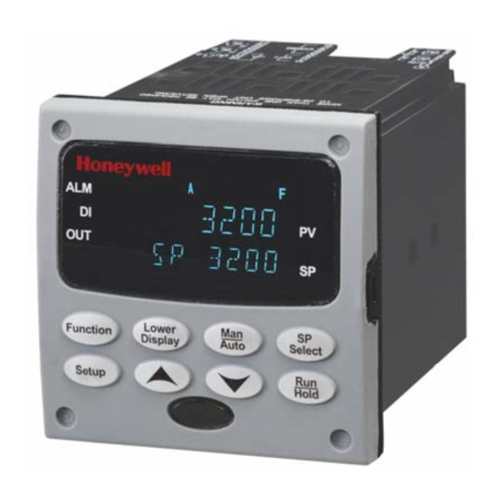
This allows more aggressive tuning to co-exist with smooth PV response. It can be enabled or disabled depending on the application or the control criteria. 1.2 Operator Interface Figure 1-1 UDC3200 Operator Interface 12/04 UDC3200 Universal Digital Controller Product Manual... -
Page 18: Function Of Displays And Keys
Decreases setpoint or output value. Decreases Increases the configuration values or the configuration values or changes functions in changes functions in Configuration Configuration mode groups. mode groups. Infrared transceiver NEMA4X and IP66 screw attachment (each corner) UDC3200 Universal Digital Controller Product Manual 12/04... -
Page 19: Process Instrument Explorer Software
• Create/edit configurations live, just connect software to the controller via a communications port. • Create/edit configurations offline and download to controller later via a communications port. • Communication types available on every UDC3200: o Infrared (standard) o RS 485(optional) o Ethernet (optional) •... -
Page 20: Ce Conformity (Europe)
Council Directives: 73/23/EEC, the Low Voltage Directive, and 89/336/EEC, the EMC Directive. Conformity of this product with any other “CE Mark” Directive(s) shall not be assumed. Product Classification: Class I: Permanently connected, panel-mounted Industrial Control Equipment with protective earthing (grounding) (EN61010-1). UDC3200 Universal Digital Controller Product Manual 12/04... - Page 21 WARNING If this equipment is used in a manner not specified by the manufacturer, the protection provided by the equipment may be impaired. 12/04 UDC3200 Universal Digital Controller Product Manual...
-
Page 23: Installation
2 Installation 2.1 Overview Introduction Installation of the UDC3200 consists of mounting and wiring the controller according to the instructions given in this section. Read the pre-installation information, check the model number interpretation (Subsection 2.3), and become familiar with your model selections, then proceed with installation. -
Page 24: Condensed Specifications
• Check that the model number shown on the inside of the case agrees with what you have ordered. 2.2 Condensed Specifications Honeywell recommends that you review and adhere to the operating limits listed in Table 2-1 when you install your controller. Table 2-1 Condensed Specifications... - Page 25 Analog Inputs and Outputs: Are isolated from each other and all other circuits at 850 Vdc for 2 seconds. Digital Inputs and Digital Outputs: Electrically isolated from all other circuits to withstand a HIPOT potential of 850 Vdc for 2 seconds per Annex K of EN61010-1. 12/04 UDC3200 Universal Digital Controller Product Manual...
- Page 26 60 ± 0.2 59 to 61 58 to 62 * The maximum moisture rating only applies up to 40 °C (104 °F). For higher temperatures, the RH specification is derated to maintain constant moisture content. UDC3200 Universal Digital Controller Product Manual 12/04...
-
Page 27: Model Number Interpretation
Key Number _ _ _ _ _ _ _ _ _ _ _ _ _ - _ _ _ _ _ KEY NUMBER - UDC3200 Single Loop Controller Description Selection Availability Digital Controller for use with 90 to 264Vac Power... -
Page 28: Figure 2-1 Model Number Interpretation
Product Information on CD - All Languages English Manual French Manual Manuals German Manual Italian Manual Spanish Manual None Certificate Certificate of Conformance (F3391) TABLE VI No Selection None Figure 2-1 Model Number Interpretation UDC3200 Universal Digital Controller Product Manual 12/04... -
Page 29: Control And Alarm Relay Contact Information
Table 2-3 Alarm Relay Contact Information Unit Alarm Relay Variable NOT in Alarm State Variable in Alarm State Power Wiring Relay Indicators Relay Indicators Contact Contact N.O. Open Open N.C. Closed Closed N.O. Closed Open N.C. Open Closed 12/04 UDC3200 Universal Digital Controller Product Manual... -
Page 30: Mounting
Mounting Notes Before mounting the controller, refer to the nameplate on the outside of the case and make a note of the model number. It will help later when selecting the proper wiring configuration. UDC3200 Universal Digital Controller Product Manual 12/04... -
Page 31: Table 2-4 Mounting Procedure
For water-protected installation, install four screws with washers into the four recessed areas in the corners of the front bezel (Figure 2-3). Push the point of the screw through the center piercing the elastomeric material and then tighten screws to 5 lb-in (56 N•cm). 12/04 UDC3200 Universal Digital Controller Product Manual... -
Page 32: Wiring
Vac, 42.4 Vpeak, or 60 Vdc) wiring per Permissible Wiring Bundling, Table 2-5. Electrical Noise Precautions Electrical noise is composed of unabated electrical signals which produce undesirable effects in measurements and control circuits. UDC3200 Universal Digital Controller Product Manual 12/04... -
Page 33: Table 2-5 Permissible Wiring Bundling
• 4-20 mA output signal wiring Digital input signals • Low voltage alarm relay output wiring • Low voltage wiring to solid state type control circuits • Low voltage wiring to open collector type control circuits 12/04 UDC3200 Universal Digital Controller Product Manual... -
Page 34: Wiring Diagrams
“Output 1” is HEAT while “Output 2” is COOL. When Three Position Step Control is configured, “Output 1” is OPEN while “Output 2” is CLOSE. The Output 1/2 option “Single Relay” can be any of the following selections: Electro-Mechanical Relay, Solid- State Relay or Open Collector Output. UDC3200 Universal Digital Controller Product Manual 12/04... -
Page 35: Table 2-6 Universal Output Functionality And Restrictions
* To obtain this output algorithm type with these Output 1/2 Options: 1) Configure the OUTALG selection as “TIME D”; 2) Configure Auxiliary Output for “OUTPUT” and; 3) Scale the Auxiliary Output as necessary for the desired output algorithm type. For these 12/04 UDC3200 Universal Digital Controller Product Manual... -
Page 36: Figure 2-4 Composite Wiring Diagram
Outputs 1 and 2 Terminals. See Figure 2-8 through Figure 2-14. Input #2 Terminals. See Figure 2-7. Input #1 Terminals. See Figure 2-6. Aux. Output and Digital Inputs Terminals. See Figure 2-17. Communications Terminals. See Figure 2-15 and Figure 2-16. UDC3200 Universal Digital Controller Product Manual 12/04... -
Page 37: Figure 2-5 Mains Power Supply
CAUTION Applying 90-264 Vac to an instrument rated for 24 Vac/dc will severely damage the instrument and is a fire and smoke hazard. Figure 2-5 Mains Power Supply 12/04 UDC3200 Universal Digital Controller Product Manual... -
Page 38: Figure 2-6 Input 1 Connections
The millivolt values for the Thermocouple Differential Input are for a pair of J thermocouples at an ambient temperature mean of 450°F / 232°C. Figure 2-6 Input 1 Connections UDC3200 Universal Digital Controller Product Manual 12/04... -
Page 39: Figure 2-7 Input 2 Connections
Input 2 is used to measure the Slidewire Input for Position Proportional Control. Input 2 is used to measure the Slidewire Input for Position Proportional Control. xxxx xxxx xxxx Figure 2-7 Input 2 Connections 12/04 UDC3200 Universal Digital Controller Product Manual... -
Page 40: Figure 2-8 Electromechanical Relay Output
Electromechanical relays are rated at 5 Amps @ 120 Vac or 240 Vac or 30 Vdc. Customer should size fuses accordingly. Use Fast Blo fuses only. Figure 2-8 Electromechanical Relay Output See Table 2-6 for relay terminal connections for other Output Algorithm Types. UDC3200 Universal Digital Controller Product Manual 12/04... -
Page 41: Figure 2-9 Solid State Relay Output
Electromechanical relays are rated at 5 Amps @ 120 Vac or 240 Vac or 30 Vdc. Customer should size fuses accordingly. Use Fast Blo fuses only. Figure 2-9 Solid State Relay Output See Table 2-6 for relay terminal connections for other Output Algorithm Types. 12/04 UDC3200 Universal Digital Controller Product Manual... -
Page 42: Figure 2-10 Open Collector Output
Electromechanical relays are rated at 5 Amps @ 120 Vac or 240 Vac or 30 Vdc. Customer should size fuses accordingly. Use Fast Blo fuses only. Figure 2-10 Open Collector Output See Table 2-6 for relay terminal connections for other Output Algorithm Types. UDC3200 Universal Digital Controller Product Manual 12/04... -
Page 43: Figure 2-11 Dual Electromechanical Relay Option Output
Electromechanical relays are rated at 5 Amps @120 Vac or 240 Vac or 30 Vdc Customer should size fuses accordingly. Use Fast Blo fuses only. Figure 2-12 Current Output See Table 2-6 for relay terminal connections for other Output Algorithm Types. 12/04 UDC3200 Universal Digital Controller Product Manual... -
Page 44: Figure 2-13 Position Proportional Or Three Position Step Control Connections W/O Dual Relay Option
30 Vdc. Customer should size fuses accordingly. Use Fast Blo fuses only. See Input 2 Wiring Diagram for Slidewire Connections. xxxx Figure 2-14 Position Proportional or Three Position Step Control Connections with Dual Relay Option UDC3200 Universal Digital Controller Product Manual 12/04... -
Page 45: Figure 2-15 Rs-422/485 Communications Option Connections
Figure 2-16 and Table 2-7 shows how to connect a UDC to a MDI Compliant Hub or Switch utilizing a straight-through cable or for connecting a UDC to a PC utilizing a crossover cable. 12/04 UDC3200 Universal Digital Controller Product Manual... -
Page 46: Table 2-7 Terminals For Connecting A Udc To A Mdi Compliant Hub Or Switch
Connect shield to ground at one Connect shield end only. to ground at one end only. Auxiliary Output and Digital Input 2 are mutually exclusive. Figure 2-17 Auxiliary Output and Digital Inputs Option Connections UDC3200 Universal Digital Controller Product Manual 12/04... -
Page 47: Figure 2-19 Transmitter Power For 4-20 Ma - 2 Wire Transmitter Using Auxiliary Output
If necessary, install a zener diode here to reduce voltage at the transmitter. A 1N4733 will reduce the voltage at the transmitter to approximately 25 Vdc. Figure 2-19 Transmitter Power for 4-20 mA — 2 Wire Transmitter Using Auxiliary Output 12/04 UDC3200 Universal Digital Controller Product Manual... -
Page 48: Configuration
3.10 Input 2 Set Up Group 3.11 Control Set Up Group 3.12 Options Set Up Group 3.13 Communications Set Up Group 3.14 Alarms Set Up Group 3.15 Display Set Up Group 3.16 Configuration Record Sheet UDC3200 Universal Digital Controller Product Manual 12/04... -
Page 49: Configuration Prompt Hierarchy
AUX OUT LOW VAL HIGH VAL CORANGE DIG1 INP DIG1 COM DIG2 INP DIG2 COM Com ADDR ComSTATE IR ENABLE BAUD TX DELAY WSFLOAT SHEDENAB SHEDTIME SHEDMODE SHEDSP UNITS CSP RATO CSP BIAS LOOPBACK 12/04 UDC3200 Universal Digital Controller Product Manual... - Page 50 A2S1 EV A2S2TYPE A2S2 VAL A2S2 H L A2S2 EV AL HYST ALM OUT1 BLOCK DIAGNOST DISPLAY DECIMAL TEMPUNIT PWR FREQ RATIO 2 LANGUAGE CALIB USED FOR FIELD CALIBRATION STATUS VERSION FAILSAFE TESTS UDC3200 Universal Digital Controller Product Manual 12/04...
-
Page 51: Configuration Procedure
If you do not press any keys for 30 seconds, the controller times out and reverts to the mode and associated display used prior to entry into Set Up mode. 12/04 UDC3200 Universal Digital Controller Product Manual... -
Page 52: Tuning Set Up Group
RATE action, in minutes, affects the controller's output whenever the deviation is changing; and affects it more when the deviation is changing faster. Also defined as "HEAT" Rate on Duplex models for variations of Heat/Cool applications. UDC3200 Universal Digital Controller Product Manual 12/04... - Page 53 0.02 to 50.00 These are the same as above except that they apply RSET2MIN to Duplex models for the "COOL" zone of Heat/Cool RSET2RPM applications or for the second set of PID constants. 12/04 UDC3200 Universal Digital Controller Product Manual...
- Page 54 + CONF—Tuning, SP Ramp, and Accutune groups are read/write. All other groups are read only. Calibration and Keyboard Lockout groups are not available. + VIEW + VIEW—Tuning and Setpoint Ramp parameters are read/write. No other parameters are viewable. UDC3200 Universal Digital Controller Product Manual 12/04...
- Page 55 ATTENTION Can only be viewed if LOCKOUT is configured for NONE. SP SEL SETPOINT SELECT KEY LOCKOUT—Allows you to disable the Setpoint Select key DISABLE DISABLE ENABLE ENABLE ATTENTION Can only be viewed if LOCKOUT is configured for NONE. 12/04 UDC3200 Universal Digital Controller Product Manual...
-
Page 56: Sp Ramp Set Up Group
0 to 255 minutes TIME MIN SETPOINT RAMP TIME—Enter the number of minutes desired to reach the final setpoint. A ramp time of “0” implies an immediate change of setpoint. UDC3200 Universal Digital Controller Product Manual 12/04... - Page 57 The ramping (current) setpoint can be viewed as SPn in the lower display. Entering a 0 will imply an immediate step change in Setpoint (i.e., no rate applies). 12/04 UDC3200 Universal Digital Controller Product Manual...
- Page 58 SEG1RAMP or 0-99 hours.0-59 minutes Segment #1 Ramp Time or Engineering units/minute Segment #1 Ramp Rate SEG1RATE Select TIME, EU/MIN, or EU/HR at prompt Engineering units/hour RAMPUNIT. All ramps will use the same selection. UDC3200 Universal Digital Controller Product Manual 12/04...
- Page 59 Selections are same as Same as above above. SEG3RATE SEG4 SP SEG4TIME SEG5RAMP or SEG5RATE SEG6 SP SEG6TIME SEG7RAMP or SEG7RATE SEG8 SP SEG8TIME SEG9RAMP or SEG9RATE SG10 SP SG10TIME SG11RAMP or SG11RATE SG12 SP SG12TIME 12/04 UDC3200 Universal Digital Controller Product Manual...
-
Page 60: Accutune Set Up Group
DISABLE DISABLE—Disables Fuzzy Overshoot Suppression. ENABLE ENABLE—The instrument uses Fuzzy Logic to suppress or minimize any overshoot that may occur when PV approaches SP. It will not recalculate any new tuning parameters. UDC3200 Universal Digital Controller Product Manual 12/04... - Page 61 • digital input detected • in heat region of output but a cool output was calculated, or vice versa. SP2—LSP2 not configured or a Setpoint other than LSP1 or LSP2 is in use. 12/04 UDC3200 Universal Digital Controller Product Manual...
-
Page 62: Algorithm Set Up Group
(hysteresis) of the on and off states of each output. Both Deadband and Hysteresis are separately adjustable. With no relay action the controller will read 50 %. ATTENTION Other prompts affected: OUT HYST and DEADBAND UDC3200 Universal Digital Controller Product Manual 12/04... - Page 63 If you select PD with Manual Reset you can also configure the following variations: • PD (Two Mode) control, • P (Single Mode) control. Set Rate (D) to 0. ATTENTION Other prompts affected: MAN RSET in the Tuning Set Up group 12/04 UDC3200 Universal Digital Controller Product Manual...
- Page 64 Alarm 1 is activated at the end of the timeout period. 0:00 to 99:59 PERIOD PERIOD allows you to configure the length of timeout period (from 0 to 99 hours: 59 minutes). UDC3200 Universal Digital Controller Product Manual 12/04...
- Page 65 Three Position Step Control applications. The following formula applies: Controller Output = PID Output + (Input A x Ratio A + Bias A ) x (100 / Input A Range) 12/04 UDC3200 Universal Digital Controller Product Manual...
- Page 66 Alg1 = K x [{(Input A x Ratio A + Bias A) x (Input C x Ratio C + Bias C)} / (Input B x Ratio B + Bias B)] x (Calc Hi – Calc Lo) + Alg1Bias UDC3200 Universal Digital Controller Product Manual 12/04...
- Page 67 Zirconium Oxide Oxygen Probe to measure Percent of Oxygen in a range of 0 to 40 % . This algorithm requires a temperature range within the region of 800 °F to 3000 °F. 12/04 UDC3200 Universal Digital Controller Product Manual...
- Page 68 ALGORITHM 1, INPUT C SELECTION will represent one of the available selections. NONE None INPUT 1 Input 1 INPUT 2 Input 2 OUTPUT Output – Should not be used for Three Position Step Control applications) UDC3200 Universal Digital Controller Product Manual 12/04...
- Page 69 3. If the Ratio for Input 2 is set to 0.0, then a constant value may be used for the Input 2 value via the Input 2 Bias setting. For this configuration, the Input 2 low range and the Sooting diagnostic messages are disabled. 12/04 UDC3200 Universal Digital Controller Product Manual...
-
Page 70: Figure 3-1 Mass Flow Example
DP value by "90" to normalize the equation. (IN3 + 14.7) SCFM x 650 (IN2 + 460) Rearranging terms: (IN3 + 14.7) SCFM x 650 Example continued (IN2 + 460) on next page Constant = K Variable 22049 UDC3200 Universal Digital Controller Product Manual 12/04... - Page 71 170 F + 460 50 psi + 14.7 170 F + 460 20 psi + 14.7 110 F + 460 50 psi + 14.7 110 F + 460 20 psi + 14.7 22050 12/04 UDC3200 Universal Digital Controller Product Manual...
-
Page 72: Output Set Up Group
100 to 1000 ohms feedback slidewire. This output algorithm selection forces Input 2 to the SLIDEW selection when the Control Algorithm is any selection other than 3PSTEP. ATTENTION Other prompts affected: DEADBAND, IN2 TYPE UDC3200 Universal Digital Controller Product Manual 12/04... - Page 73 • The Auxiliary Current Output is scaled as desired for 0-50 % controller output. • Deadband for this configuration only applies to the Current Output. The Auxiliary Output must have the Deadband scaled in. FOR EXAMPLE: 12/04 UDC3200 Universal Digital Controller Product Manual...
- Page 74 Output algorithm. This is the time it takes the motor to travel from 0 to 100% (fully closed to fully open). This time can usually be found on the nameplate of the motor. UDC3200 Universal Digital Controller Product Manual 12/04...
- Page 75 4-20 mA output or 0-20 mA output 0-20mA operation without the need for recalibration of the instrument. ATTENTION Changing the Current Output Range will result in the loss of Field Calibration values and will restore Factory Calibration values. 12/04 UDC3200 Universal Digital Controller Product Manual...
-
Page 76: Input 1 Set Up Group
0-5 V—0 to 5 Volts 0-5 V 1-5 V—1 to 5 Volts 1-5 V 0-10 V—0 to 10 Volts 0-10 V TC DIFF—Thermocouple Differential TC DIFF Carbon—Carbon Probe Input CARBON Oxygen—Oxygen Probe Input OXYGEN UDC3200 Universal Digital Controller Product Manual 12/04... - Page 77 BIAS ON INPUT 1 — Bias is used to compensate (in engineering units) the input for drift of an input value due to deterioration of a sensor, or some other cause. Select the bias value you want on Input 1. 12/04 UDC3200 Universal Digital Controller Product Manual...
- Page 78 (across the transmitter terminals). Otherwise, the input at the instrument terminals will always be 0 mA (i.e., within the normal operating range) when the 0-20 mA line is opened. UDC3200 Universal Digital Controller Product Manual 12/04...
- Page 79 Radiamatic input signal that is the ratio of the actual energy emitted from the target to the energy which would be emitted if the target were a perfect radiator. Available only for Radiamatic inputs. 12/04 UDC3200 Universal Digital Controller Product Manual...
-
Page 80: Input 2 Set Up Group
0-100mV 0-5 V—0 to 5 Volts 0-5 V 1-5 V—1 to 5 Volts 1-5 V 0-10 V—0 to 10 Volts 0-10 V TC DIFF—Thermocouple Differential TC DIFF SLIDEW—Slidewire (For Position Proportional SLIDEW Applications) UDC3200 Universal Digital Controller Product Manual 12/04... - Page 81 (selected in the CONTROL Set up Group) is applied when a failed input is detected (does not apply for an input out of range). Diagnostic message IN2 FAIL is intermittently flashed on the lower display. 12/04 UDC3200 Universal Digital Controller Product Manual...
- Page 82 Radiamatic input signal that is the ratio of the actual energy emitted from the target to the energy which would be emitted if the target were a perfect radiator. Available only for Radiamatic inputs. UDC3200 Universal Digital Controller Product Manual 12/04...
-
Page 83: Control Set Up Group
Press this key until you see PID SET1 or PID SET2 then press to switch between sets. Configure the values for: Gain, Rate, Reset, Cycle Time Gain #2, Rate #2, Reset #2, Cycle #2 Time 12/04 UDC3200 Universal Digital Controller Product Manual... - Page 84 TWO LOCAL SETPOINTS—This selection lets you switch between two local setpoints using the Select Select Select key. THREE THREE LOCAL SETPOINTS—This selection lets you switch between three local setpoints using the Select Select Select UDC3200 Universal Digital Controller Product Manual 12/04...
- Page 85 MANUAL, LSP—At power-up, the controller will use manual mode with the local setpoint displayed. A LSP AUTOMATIC MODE, LAST LSP—At power-up, the controller will use automatic mode with the last local setpoint used before power down displayed. 12/04 UDC3200 Universal Digital Controller Product Manual...
- Page 86 OUTPUT CHANGE RATE—Enables or disables the Output Change Rate. The maximum rate is set at prompt PCT/M UP or PCT/M DN. Only available for PID-A, PID-B, PD+MR control algorithms. ENABLE ENABLE—Allows output rate. DISABLE DISABLE—Disables output rate. UDC3200 Universal Digital Controller Product Manual 12/04...
- Page 87 ON/OFF states of each control output. This is the difference between the value of the process variable at which the control outputs energize and the value at which they de-energize. Only applicable for ON/OFF control. 12/04 UDC3200 Universal Digital Controller Product Manual...
- Page 88 Proportional (P) term of the PID algorithm: PB PCT PROPORTIONAL BAND selects units of percent proportional band for the P term of the PID algorithm. Where: PB % = 100 % FS GAIN UDC3200 Universal Digital Controller Product Manual 12/04...
- Page 89 SP = 1500 and the SP HiLIM is changed to 1200, the new local setpoint will be 1200. NOTE 5: Reset limits and Dropoff are not displayed when Three Position Step Control is configured. 12/04 UDC3200 Universal Digital Controller Product Manual...
-
Page 90: Options Group
1600 °F display = 100 % output INPUT 2 INPUT 2 represents the value of the configured range of input 2. PROCESS VARIABLE—Represents the value of the Process Variable. PV = Input XxRatioX + BiasX UDC3200 Universal Digital Controller Product Manual 12/04... - Page 91 0-20mA output operation without the need for recalibration of the instrument. ATTENTION Changing the Auxiliary Current Output Range will result in the loss of Field Calibration values and will restore Factory Calibration values. 12/04 UDC3200 Universal Digital Controller Product Manual...
- Page 92 TO LOCAL SETPOINT TWO—Contact closure puts the controller into local setpoint 2. TO 3SP TO LOCAL SETPOINT THREE—Contact closure puts the controller into local setpoint 3. TO DIR TO DIRECT ACTION—Contact closure selects direct controller action. UDC3200 Universal Digital Controller Product Manual 12/04...
- Page 93 Manual to Automatic is bumpless. When the switch is closed, the output can be adjusted from the keyboard. TO LOCK KEYBOARD LOCKOUT—Contact closure disables all keys. Lower display shows LOCKED if a key is pressed. 12/04 UDC3200 Universal Digital Controller Product Manual...
- Page 94 Manual mode with the output set to the Output High Limit configuration. MAN lights and the Output value is shown on the lower display. Opening the switch has no effect. ATTENTION Does not apply to Three Position Step Control. UDC3200 Universal Digital Controller Product Manual 12/04...
- Page 95 PLUS RUN SETPOINT PROGRAM/RAMP— Contact closure starts SP Program/Ramp if enabled. DIG INP2 Same selections as for DIGITAL INPUT 2 SELECTIONS Digital Input 1 DIG2COMB Same selections as Digital DIGITAL INPUT 2 COMBINATIONS Input 1 Combinations 12/04 UDC3200 Universal Digital Controller Product Manual...
-
Page 96: Communications Group
This value is used for both RS-485 and IR Communications, but for IR Communications, values below 19200 baud are interpreted as being 19200 baud. 4800 BAUD 4800 9600 BAUD 9600 19200 19200 BAUD 38400 38400 BAUD UDC3200 Universal Digital Controller Product Manual 12/04... - Page 97 The controller will return to manual mode at the output value selected at Control prompt FAILSAFE. TO AUTO TO AUTO—AUTOMATIC MODE, LAST SP—The controller will return to the automatic mode and the last setpoint used before shed. 12/04 UDC3200 Universal Digital Controller Product Manual...
- Page 98 If it is connected, only one instrument should run the loopback test at a time. The host computer should not be transmitting on the link while the loopback test is active. UDC3200 Universal Digital Controller Product Manual 12/04...
-
Page 99: Alarms Set Up Group
Value in engineering units A2S2 VAL ALARM 2 SETPOINT 2 VALUE—This is the value at which you want the alarm type chosen in prompt A2S2TYPE to actuate. The details are the same as A1S1 VAL. 12/04 UDC3200 Universal Digital Controller Product Manual... - Page 100 AxSx VAL entry. This value is in seconds with a range of 0 to 3600 seconds. A setting of 0 is equivalent to an instantaneous loop break when the output reaches one of its limit UDC3200 Universal Digital Controller Product Manual 12/04...
- Page 101 A1S1TYPE to alarm the beginning or end of a segment in setpoint Ramp/Soak programming. BEGIN BEGINNING OF SEGMENT END OF SEGMENT ATTENTION Alarms configured for events will not operate on Setpoint Program segments of zero length. 12/04 UDC3200 Universal Digital Controller Product Manual...
- Page 102 Configure the hysteresis of the alarms based on INPUT signals as a % of input range span. Configure the hysteresis of the alarm based on OUTPUT signals as a % of the full scale output range. UDC3200 Universal Digital Controller Product Manual 12/04...
- Page 103 Alarm is activated. This configuration is in addition to whatever was selected for AxSxTYPE. DISABLE DISABLE—Disables Diagnostic Alarm ALARM 1 ALARM 1—Alarm 1 is diagnostic alarm ALARM 2 ALARM 2—Alarm 2 is diagnostic alarm 12/04 UDC3200 Universal Digital Controller Product Manual...
-
Page 104: Display Set Up Group
INPUT 2 RATIO—This enables the Ratio for Input 2 to be set from the front panel. Input 2 must be installed and enabled for this configuration to operate. DISABLE DISABLE—Disables setting Ratio 2 from front panel. UDC3200 Universal Digital Controller Product Manual 12/04... - Page 105 Definition Upper Display ENABLE ENABLE—Allows the Ratio for Input 2 to be set through the keyboard. LANGUAGE LANGUAGE—This selection designates the prompt language. ENGLISH ENGLISH FRENCH FRENCH GERMAN GERMAN SPANISH SPANISH ITALIAN ITALIAN 12/04 UDC3200 Universal Digital Controller Product Manual...
-
Page 106: Configuration Record Sheet
IN2 HIGH __________ 1000 AT ERROR Read Only NONE IN2 LOW __________ RATIO 2 __________ 1.00 BIAS IN2 __________ FILTER 2 __________ BURNOUT2 __________ NONE EMMISIV2 __________ 0.00 NOTE 1: Model Number dependent. UDC3200 Universal Digital Controller Product Manual 12/04... - Page 107 __________ NONE SHEDTIME __________ 30.0 Email Subj __________ SHEDMODE __________ LAST __________ SHEDSP __________ TO LSP __________ UNITS __________ PERCNT __________ CSP RATO __________ __________ CSP BIAS __________ __________ LOOPBACK __________ DISABLE __________ 12/04 UDC3200 Universal Digital Controller Product Manual...
-
Page 108: Monitoring And Operating The Controller
4.14 Three Position Step Control Algorithm 4.15 Setting A Failsafe Output Value For Restart After A Power Loss 4.16 Setting Failsafe Mode 4.17 Setpoint Rate/Ramp/Program Overview 4.18 Setpoint Rate 4.19 Setpoint Ramp 4.20 Setpoint Ramp/Soak Programming UDC3200 Universal Digital Controller Product Manual 12/04... -
Page 109: Operator Interface
NONE. Thereafter, that selected number must be used to change the lockout level from something other than NONE. Write the number on the Configuration Record Sheet in the configuration ATTENTION section so you will have a permanent record. 12/04 UDC3200 Universal Digital Controller Product Manual... -
Page 110: Lockout Feature
This will be your security code. 4.4 Lockout Feature Introduction The lockout feature in the UDC3200 is used to inhibit changes (via keyboard) of certain functions or parameters by unauthorized personnel. Lockout levels There are different levels of Lockout depending on the level of security required. These levels are: •... - Page 111 When a key is pressed and the prompt “Key Error” appears in the lower display, it will be for one of the following reasons: • Parameter not available or locked out • Not in setup mode, press key first SET UP • Individual key locked out. 12/04 UDC3200 Universal Digital Controller Product Manual...
-
Page 112: Monitoring Your Controller
Setpoint (Local 1, Local 2, Local 3, Remote Setpoint or Computer Setpoint) The upper left digit of the display is used to show other annunciator functions T—Accutuning in process C—Computer overide active O—Output override active UDC3200 Universal Digital Controller Product Manual 12/04... -
Page 113: Viewing The Operating Parameters
Limit Cycle Tuning with the objective of producing damped or Dahlin tuning parameters, depending upon the detected process deadtime. The tuning parameters calculated by this selection are aimed at reducing PV overshoot of the SP setting. 12/04 UDC3200 Universal Digital Controller Product Manual... -
Page 114: Diagnostic Messages
Monitoring and Operating the Controller 4.5.3 Diagnostic Messages The UDC3200 performs background tests to verify data and memory integrity. If there is a malfunction, a diagnostic message will be shown on the lower display. In the case of more than one simultaneous malfunction, only the highest priority diagnostic message will be displayed. -
Page 115: Figure 4-2 Functional Overview Block Diagram Of The Udc3200 Controller
Input 1 INPUT C Input 2 Output 1 FEEDFO RWARD LSP3 LSP1 SUMMER OR LSP2 MULTIPLIER Manual Mode Output To Final OUTPUT Control Element Figure 4-2 Functional Overview Block Diagram of the UDC3200 Controller 12/04 UDC3200 Universal Digital Controller Product Manual... -
Page 116: Start Up Procedure For Operation
Refer to Tuning Set Up group to ensure that the selections for PBor GAIN, RATE T, and I MIN, or I RPM have been entered. Use Accutune to tune the controller; see the procedure in this section. UDC3200 Universal Digital Controller Product Manual 12/04... -
Page 117: Control Modes
(0 % to 100 % for a time proportioning output or –5 % to 105 % for a current output). 12/04 UDC3200 Universal Digital Controller Product Manual... -
Page 118: What Happens When You Change Modes
If LSP tracking is not configured, the local setpoint will not be altered when the transfer is made. 4.8 Setpoints Introduction You can configure the following setpoints for the UDC3200 controller. • A Single Local Setpoint • 2 Local Setpoints •... -
Page 119: Table 4-8 Procedure For Changing The Local Setpoints
• you attempt to change the setpoint while a setpoint ramp is enabled, or • if you attempt to change the setpoint with the setpoint select function key disabled. • appears to the left of the active setpoint 12/04 UDC3200 Universal Digital Controller Product Manual... -
Page 120: Timer
TIME REMAINING will show as a decreasing Hrs:Min value (HH:MM) or Min:Sec value (MM:SS) plus a counterclockwise rotating clock face. ELAPSED TIME will show as an increasing Hrs:Min value(HH:MM) or Min:Sec value (MM:SS) plus a clockwise rotating clock face. UDC3200 Universal Digital Controller Product Manual 12/04... -
Page 121: Accutune Iii
• TUNE has been enabled see to Subsection 3.6 - Accutune Set Up Group for details. Tuning indicators A “T” will show in the leftmost alphanumeric of the upper display until tuning is completed. 12/04 UDC3200 Universal Digital Controller Product Manual... -
Page 122: Tune For Simplex Outputs
Lower in the lower display. Display Display Display Until LSP1 is to the desired value. Switch to Until the “A” indicator is lighted (on “Automatic” Mode controllers with Manual option). Auto Auto Auto UDC3200 Universal Digital Controller Product Manual 12/04... -
Page 123: Tune For Duplex (Heat/Cool)
PID SET 2. Configuration Check for Duplex See Subsection 3.6 - Accutune Set Up Group for details. Make sure: • TUNE has been enabled • DUPLEX has been configured to Manual, Automatic or Disabled 12/04 UDC3200 Universal Digital Controller Product Manual... -
Page 124: Using Automatic Tune At Start-Up For Duplex (Heat/Cool)
Upper display will show a “T” as Lower Lower Lower long as ACCUTUNE process is Display Display Display operating. When process completes, tuning parameters are calculated and lower display will show “NO TUNE” prompt. UDC3200 Universal Digital Controller Product Manual 12/04... -
Page 125: Using Blended Tune At Start-Up For Duplex (Heat/Cool)
Operation Press Result Configure LSP1 Until SP (Local Setpoint 1) shows Lower Lower Lower in the lower display. Display Display Display Until LSP1 is a value within the Heat Zone (output above 50%). 12/04 UDC3200 Universal Digital Controller Product Manual... -
Page 126: Table 4-14 Procedure For Using Manual Tune For Cool Side Of Duplex Control
Upper display will show a “T” as Lower Lower Lower long as ACCUTUNE process is Display Display Display operating. When process completes, tuning parameters are calculated and lower display will show “NO TUNE” prompt. UDC3200 Universal Digital Controller Product Manual 12/04... -
Page 127: Error Codes
To abort Accutune and return to the last previous operation (SP or output level), press key to abort the Accutune process or increment from the “DO SLOW” or MAN-AUTO “DO FAST” prompt to the “TUNE OFF” prompt. 12/04 UDC3200 Universal Digital Controller Product Manual... -
Page 128: Fuzzy Overshoot Suppression
(this does not apply for Duplex control, which always uses two PID sets). The sets can be: • keyboard selected, • automatically switched when a predetermined process variable value is reached, • automatically switched when a predetermined setpoint value is reached. UDC3200 Universal Digital Controller Product Manual 12/04... -
Page 129: Table 4-17 Set Up Procedure
Until you see: Function Function Function Value for Upper Display = (the switchover value) 2 PVSW or Lower Display = SW VAL 2 SPSW Selection To select the switchover value in the upper display. 12/04 UDC3200 Universal Digital Controller Product Manual... -
Page 130: Alarm Setpoints
Installation for alarm relay contact information. There are four alarm setpoints, two for each alarm. The type and state (High or Low) is selected during configuration. See Subsection 3.13 – Configuration for details. UDC3200 Universal Digital Controller Product Manual 12/04... -
Page 131: Table 4-19 Procedure For Displaying Alarm Setpoints
MANUAL, RSP, and F’SAFE selections do not have setpoint values. Change a value To change any alarm setpoint value in the upper display. Return to Normal Lower Lower Lower Display Display Display Display 12/04 UDC3200 Universal Digital Controller Product Manual... -
Page 132: Three Position Step Control Algorithm
Table 4-20 Procedure for Displaying 3Pstep Motor Position Step Operation Press Result Access the Until you see: Lower Lower Lower Displays Upper Display = PV Display Display Display Lower Display = OT (The estimated motor position in %) UDC3200 Universal Digital Controller Product Manual 12/04... -
Page 133: Setting A Failsafe Output Value For Restart After A Power Loss
Select a value To select a failsafe output value in the upper display Return to Normal At power up, the output will go to the value set. Lower Lower Lower Display Display Display Display 12/04 UDC3200 Universal Digital Controller Product Manual... -
Page 134: Setting Failsafe Mode
This section explains the operation of each selection and configuration reference where necessary. PV Hot Start This is a standard feature. At power-up, the setpoint is set to the current PV value and the Rate or Ramp or Program then starts from this value. UDC3200 Universal Digital Controller Product Manual 12/04... -
Page 135: Setpoint Rate
1 to 255 minutes. You can RUN or HOLD the ramp at any time. Configuration Check Make sure • SPRAMP is enabled • SP RATE and SPPROG are not running. 12/04 UDC3200 Universal Digital Controller Product Manual... -
Page 136: Table 4-23 Running A Setpoint Ramp
The ramp is placed in hold at the beginning. Configure the mode at Set Up Group “CONTROL”, function prompt “PWR MODE”. See Subsection 3.11 – CONTROL SETUP GROUP Prompts. UDC3200 Universal Digital Controller Product Manual 12/04... -
Page 137: Setpoint Ramp/Soak Programming
(Figure 4-4) and fill in the information for each segment. This will give you a record of how the program was developed. Operation Refer to Table 4-25 Run/Monitor the program. Program Contents Table 4-24 lists all the program contents and a description of each. 12/04 UDC3200 Universal Digital Controller Product Manual... -
Page 138: Table 4-24 Program Contents
PV value captured at the initial HOLD to RUN transition. If the power is cycled before program completion, upon power-up the setpoint is set to UDC3200 Universal Digital Controller Product Manual 12/04... - Page 139 The soak deviation value is the number in engineering units, above or below the setpoint, outside of which the timer halts. The range is 0 to ± 99.XX. The decimal location here corresponds decimal configuration chosen in the Display Set up group. 12/04 UDC3200 Universal Digital Controller Product Manual...
-
Page 140: Figure 4-3 Ramp/Soak Profile Example
SG11RAMP Ramp Time 3 hr:30 min. SEG2 SP Soak Time 1 hr:30 min. Soak SP SEG2TIME SG12 SP SEG3RAMP Ramp Time 1 hr. SG12TIME Soak Time 0 hr:30 min. SEG4 SP Soak SP UDC3200 Universal Digital Controller Product Manual 12/04... -
Page 141: Figure 4-4 Program Record Sheet
SPP SEG1RAMP Ramp Time SG10 TIME Soak Time SEG2 SP Soak SP SG11RAMP Ramp Time Soak Time Soak SP SEG2TIME SG12 SP SEG3RAMP Ramp Time Soak Time SG12TIME SEG4 SP Soak SP 12/04 UDC3200 Universal Digital Controller Product Manual... -
Page 142: Table 4-25 Run/Monitor Functions
Lower Display = XXRAHH.MM for Ramps or = Display Display Display segment number XXSKHH.MM for Soaks until you see and time Time remaining in the SEGMENT in hours and minutes. XX = The segment number, 1 to 12. continued UDC3200 Universal Digital Controller Product Manual 12/04... - Page 143 HOLD mode. Program cycle number is not affected. Reopening switch has no effect. Opening the contact will cause the Controller to revert to its original state. 12/04 UDC3200 Universal Digital Controller Product Manual...
-
Page 144: Input Calibration
This section describes the field calibration procedures for Input 1 and Input 2. • All input actuations in every UDC3200 controller are fully factory-calibrated and are ready for configuration by the user. • Field Calibration can improve the accuracy of the Controller if necessary for a particular application. -
Page 145: Minimum And Maximum Range Values
0 to 2372 –18 to 1300 –0.461 mV 47.513 mV 0 to 1472 –18 to 800 -0.461 mV 28.455 mV NIC L R TC 0 to 3100 –18 to 1704 –0.090 mV 20.281 mV 12/04 UDC3200 Universal Digital Controller Product Manual... - Page 146 Field Calibration of the input, with the range value limits being –4 mV to +16 mV for the zero and span values. ** The range values for Radiamatic Type RI are customer configurable within the limits shown. UDC3200 Universal Digital Controller Product Manual 12/04...
-
Page 147: Preliminary Information
Two insulated copper leads for connecting the calibrator to the controller. • Place current source at zero before switching ON. • Do not switch current sources OFF/ON while connected to the UDC3200 input. 12/04 UDC3200 Universal Digital Controller Product Manual... -
Page 148: Input 1 Or 2 Set Up Wiring
23 + Input 2 24 - 26 + Input 1 Millivolt 27 - Source Ice Bath Thermocouple Copper Leads XXXX Extension Wire Figure 5-2 Wiring Connections for Thermocouple Inputs Using an Ice Bath UDC3200 Universal Digital Controller Product Manual 12/04... -
Page 149: Thermocouple Inputs Using A Thermocouple Source
Figure 5-4. 22 R Input 2 23 + 24 - Decade 25 R Resistance 26 + Input 1 27 - Copper Leads Equal Length XXXX Figure 5-4 Wiring Connections for RTD (Resistance Thermometer Device) 12/04 UDC3200 Universal Digital Controller Product Manual... -
Page 150: Radiamatic, Millivolts, Volts Or Thermocouple Differential Inputs
Input 2 23 + 24 - Millivolt or 26 + Input 1 Volt Source 27 - XXXX Figure 5-5 Wiring Connections for Radiamatic, Thermocouple Differential, Millivolts or Volts (Except 0 to 10 Volts) UDC3200 Universal Digital Controller Product Manual 12/04... -
Page 151: To 10 Volts
23 + Input 2 250 ohms 24 - 26 + Input 1 Milliampere 250 ohms Source 27 - XXXX Figure 5-7 Wiring Connections for 0 to 20 mA or 4 to 20 mA Inputs 12/04 UDC3200 Universal Digital Controller Product Manual... -
Page 152: Input 1 Or 2 Calibration Procedure
0 % range value for your particular input sensor. See Table 5-1 for Voltage, Degrees, or Resistance equivalents for 0 % range values. • Wait 15 seconds, then go to the next step. UDC3200 Universal Digital Controller Product Manual 12/04... -
Page 153: Restore Input Factory Calibration
“Factory Calibration” for a given input actuation type by simply changing the actuation type to another type and then changing it back to the original type. Refer to Table 5-10 Restore Factory Calibration for procedure 12/04 UDC3200 Universal Digital Controller Product Manual... -
Page 154: Table 5-10 Restore Factory Calibration
Return to Normal Lower Lower Lower Operation Display Display Display The factory calibration will be restored. If the problem is not corrected, contact the Honeywell Technical Assistance Center at 1- 800-423-9883 USA and Canada UDC3200 Universal Digital Controller Product Manual 12/04... -
Page 155: Output Calibration
6.5 Restore Output Factory Calibration WARNING—SHOCK HAZARD OUTPUT CALIBRATION MAY REQUIRE ACCESS TO HAZARDOUS LIVE CIRCUITS, AND SHOULD ONLY BE PERFORMED BY QUALIFIED SERVICE PERSONNEL. MORE THAN ONE SWITCH MAY BE REQUIRED TO DE-ENERGIZE UNIT BEFORE CALIBRATION. 12/04 UDC3200 Universal Digital Controller Product Manual... -
Page 156: Current Output Calibration
Tag and disconnect the field wiring, at the rear of the controller, from terminals 21 (–) and 19 (+). See Figure 6-1. Connect a milliammeter across these terminals. Milliammeter XXXX Figure 6-1 Wiring Connections for Calibrating Current Proportional Output UDC3200 Universal Digital Controller Product Manual 12/04... -
Page 157: Table 6-2 Current Output Calibration Procedure
Normally, this will be the setting that produces 20 mA. Exit the The controller stores the span value. Function Function Function Calibration Mode To exit the calibration mode. Lower Lower Lower Display Display Display 12/04 UDC3200 Universal Digital Controller Product Manual... -
Page 158: Auxiliary Output Calibration
Tag and disconnect the field wiring, at the rear of the controller, from terminals 12 (+) and 13 (–). See Figure 6-2. Connect a milliammeter across these terminals. Milliammeter xxxx Figure 6-2 Wiring Connections for Calibrating Auxiliary Output UDC3200 Universal Digital Controller Product Manual 12/04... -
Page 159: Table 6-4 Auxiliary Output Calibration Procedure
Normally, this will be the setting that produces 20 mA. Exit the The controller stores the span value. Function Function Function Calibration Mode To exit the calibration mode. Lower Lower Lower Display Display Display 12/04 UDC3200 Universal Digital Controller Product Manual... -
Page 160: Position Proportional And Three Position Step Output Calibration
Table 6-5 Position Proportional and Three Position Step Output Calibration Procedure Step Description Press Action Enter Calibration Mode until you see Setup Setup Upper Display = CALIB Lower Display = POS PROP continued UDC3200 Universal Digital Controller Product Manual 12/04... - Page 161 When the motor stops, the display should stop counting, then, go to Step 8. DO MAN You will see: Function Function Function Upper Display = Set 0 % value (the existing zero calibration value in counts)) Lower Display = ZERO VAL 12/04 UDC3200 Universal Digital Controller Product Manual...
- Page 162 Position Proportional calibration. Exit the Calibration Mode The controller will store the 100 % value. Function Function Function To exit the calibration mode Lower Lower Lower Display Display Display Setup Setup UDC3200 Universal Digital Controller Product Manual 12/04...
-
Page 163: Restore Output Factory Calibration
Scroll through Function Function Function returns to: Functions Upper Display = the new selection Lower Display = CO RANGE 12/04 UDC3200 Universal Digital Controller Product Manual... - Page 164 Return to Normal Lower Lower Lower Operation Display Display Display The factory calibration will be restored. If the problem is not corrected, contact the Honeywell Technical Assistance Center at 1- 800-423-9883 USA and Canada UDC3200 Universal Digital Controller Product Manual 12/04...
-
Page 165: Troubleshooting/Service
• Power Failure • Current Proportional Output Failure • Time Proportional Output Failure • Time/Current - Current/Time Proportional Output Failure • Alarm Relay Output Failure • Keyboard Failure Restore Factory Configuration Software Upgrades 12/04 UDC3200 Universal Digital Controller Product Manual... -
Page 166: Troubleshooting Aids
Troubleshooting/Service Installation related problems Read the Installation section in this manual to make sure the UDC3200 has been properly installed. The installation section provides information on protection against electrical noise, connecting external equipment to the controller, and shielding and routing external wiring. -
Page 167: Table 7-1 Procedure For Identifying The Software Version
Upper Display = Software version number 32xx Lower Display = VERSION Please give this number to the Customer Support person. It will indicate which version of UDC3200 you have and help them determine a solution to your problem. 12/04 UDC3200 Universal Digital Controller Product Manual... -
Page 168: Power-Up Tests
You will see: Function Function Function results Upper Display = NO or YES YES indicates a failure Lower Display = FAILSAFE Upper Display = PASS or FAIL Function Function Function Lower Display = TEST UDC3200 Universal Digital Controller Product Manual 12/04... -
Page 169: Background Tests
Troubleshooting/Service Background Tests Introduction The UDC3200 performs ongoing background tests to verify data and memory integrity. If there is a malfunction, a diagnostic message will be displayed (blinking) in the lower display. In the case of simultaneous malfunctions, the messages will appear in sequence in the lower display. -
Page 170: Controller Failure Symptoms
In addition to the error message prompts, there are failure symptoms that can be identified by noting how the controller displays and indicators are reacting. Symptoms Compare your symptoms with those shown in Table 7-4. UDC3200 Universal Digital Controller Product Manual 12/04... -
Page 171: Table 7-4 Controller Failure Symptoms
Display does not change when a key is pressed Keyboard Malfunction Controller fails to go into “Slave” operation during communications Communications Failure Controller Displayed Auxiliary Output Auxiliary Output Output disagrees disagrees with with Displayed Auxiliary Output Auxiliary Output 12/04 UDC3200 Universal Digital Controller Product Manual... -
Page 172: Troubleshooting Procedures
You will need the following equipment in order to troubleshoot the symptoms listed in the tables that follow: • Multimeter – Capable of measuring millivolts, milliamps and resistance. • Calibration sources – T/C, mV, Volt, etc. UDC3200 Universal Digital Controller Product Manual 12/04... -
Page 173: Table 7-5 Troubleshooting Power Failure Symptoms
Use a DC milliammeter at the rear terminals to verify the output. Recalibrate the Current Refer to Section 6 - Output Calibration for Proportional output. details. Change Current Output board. Installation instructions provided with new board. Change Controller 12/04 UDC3200 Universal Digital Controller Product Manual... -
Page 174: Table 7-7 Troubleshooting Position Proportional Output Failure
If the voltage jumps at a particular position while the motor is moving, this could indicate a “deadspot” and mean that the slidewire may be worn out and need replacing. Refer to the motor manufacturer’s instructions. UDC3200 Universal Digital Controller Product Manual 12/04... -
Page 175: Table 7-8 Troubleshooting Time Proportional Output Failure
Contact should change state. 0 % open, 100 % closed. Listen for a click from the relay when the OUT1 indicator changes state. Check relay. Change relay. Change MCU board. Installation instructions supplied with the new board. 12/04 UDC3200 Universal Digital Controller Product Manual... -
Page 176: Table 7-9 Troubleshooting Current/Time Or Time/Current Proportional Output Failure
Recalibrate the controller. Refer to Section 6 - Output Calibration for details. Change MCU and/or Current Output Installation instructions supplied with new board. boards. UDC3200 Universal Digital Controller Product Manual 12/04... -
Page 177: Table 7-10 Troubleshooting Alarm Relay Output Failure
Refer to Section 2 - Installation for relay contact information. Change the relay and/or the Installation instructions supplied with the current output board. new relay or board. Change MCU board. Installation instructions supplied with the new board. 12/04 UDC3200 Universal Digital Controller Product Manual... -
Page 178: Table 7-11 Troubleshooting A Keyboard Failure
Press each key. If it works, the key name will appear in the lower display. Replace the display/keyboard if any Refer to “Parts Replacement keys do not function. Procedures ” in this section. UDC3200 Universal Digital Controller Product Manual 12/04... -
Page 179: Table 7-12 Troubleshooting A Rs-485 Communications Failure
Lower Display Press [FUNCTION] until you see: Upper Display DISABLE Lower Display LOOPBACK Press you will see: Upper Display ENABLE Lower Display LOOPBACK The test will run until the operator disables it here. 12/04 UDC3200 Universal Digital Controller Product Manual... -
Page 180: Table 7-13 Troubleshooting An Ethernet Communications Failure
Ethernet connection. See Section 2.7 for wiring diagrams. A second green LED will blink during actual Ethernet transactions. Change Ethernet Installation instructions provided with new Communications board. board. Change Controller UDC3200 Universal Digital Controller Product Manual 12/04... -
Page 181: Table 7-14 Troubleshooting Auxiliary Output Failure
Use a DC milliammeter at the rear terminals to verify the output. Recalibrate the Auxiliary output. Refer to Section 6 - Output Calibration for details. Change Auxiliary Output board. Installation instructions provided with new board. Change Controller 12/04 UDC3200 Universal Digital Controller Product Manual... -
Page 182: Restoring Factory Configuration
The instrument configuration will now be the same as it was when the instrument left the factory and all user- entered configurations since that time have been overwritten. UDC3200 Universal Digital Controller Product Manual 12/04... -
Page 183: Software Upgrades
Press the FUNCTION Key. The instrument will now display “XXXX” “ENTER2”. Write this number down. Press the FUNCTION Key. The instrument will now display “XXXX” “ENTER3”. Write this number down. Write down the Model and Serial Numbers of your instrument. 12/04 UDC3200 Universal Digital Controller Product Manual... - Page 184 Troubleshooting/Service Contact your Honeywell Representative to place an order. Please have a company purchase order number available before you call. The order entry person will ask for the following information: 1. Software Upgrade Part Number you require: Math Software Upgrade – 50004635-501, or Set Point Programming Software Upgrade –...
-
Page 185: Parts List
Exploded View Introduction Figure 8-1 is an exploded view of the UDC3200 Controller. Each part is labeled with a key number. The part numbers are listed by key number in Table 8-1. Parts not shown are listed in Table 8-2. -
Page 186: Table 8-1 Parts Identification
30754465-501 0-10 Volt Input Resistor Assembly (100K pair) 51452763-501 Mounting Kits (12 brackets & screws) Table 8-3 Software Upgrades (see Section 7.9) Part Number Description 50004635-501 Math Options 50004635-502 Set Point Programming (SPP) UDC3200 Universal Digital Controller Product Manual 12/04... -
Page 187: Removing The Chassis
Pry just enough to release it, otherwise you’ll bend or break the tab. If you break or bend the tab and can’t reattach the front snugly, you’ll need to reattach the front using the 4 NEMA4 screws provided. See Section 2.5 Mounting. 12/04 UDC3200 Universal Digital Controller Product Manual... -
Page 188: Modbus Rtu Function Codes
Function codes 20 and 21 use the RS422/485 tag IDs for accessing configuration and process-related data. These tags are fully explained in Section 10. The tag IDs represent the register addresses used in the Request Message. UDC3200 Universal Digital Controller Product Manual 12/04... -
Page 189: Table 9-1 Integer Parameter Type
Integer data is represented in sixteen bits and is transferred high byte first. Floating point data is transferred in IEEE 32-bit format. The register count definitions are: 0001 = Integer Data 0002 = Floating Point Data 12/04 UDC3200 Universal Digital Controller Product Manual... -
Page 190: Function Code 20 (14H) - Read Configuration Reference Data
The Data Byte Count is the number of data bytes of the sub response including the Reference Type but not including itself. A floating point sub response has four bytes of data and one byte representing the reference type making the data byte count equal to five. UDC3200 Universal Digital Controller Product Manual 12/04... -
Page 191: Table 9-3 Register Address Format For Function Code 20
Address(es) (Decimal) (Hex) 001 to 125 0001 to 007D analog formatted data (2 registers – IEEE 32-bit floating point) 128 to 255 0080 to 00FF integer formatted data (1 register – 16-bit integer) 12/04 UDC3200 Universal Digital Controller Product Manual... -
Page 192: Read Configuration Examples
Where: = Address = Function Code 20 (14 Hex) = Byte Count = Sub Message Length = Reference Type (IEEE Floating Point) 3F C0 00 00 = 1.50 (Value of Proportional Band) (CRC16) UDC3200 Universal Digital Controller Product Manual 12/04... - Page 193 43 C8 00 00 = 400.0 (Value of Local Setpoint #1) = Data Byte Count (Sub Message Length) = Reference Type (IEEE Floating Point) 44 60 00 00 = 896.0 (Value of Local Setpoint #2) (CRC16) 12/04 UDC3200 Universal Digital Controller Product Manual...
-
Page 194: Function Code 21 (15H) - Write Configuration Reference Data
For Infrared Transactions, add three BOFs (C0hex) at the beginning of each message and one EOF (Ffhex) at the end of each message. Reference Type Definitions The Reference Type definition is always 06. See examples in Subsection 9.4.1 UDC3200 Universal Digital Controller Product Manual 12/04... -
Page 195: Table 9-4 Register Address Format For Function Code 21
These registers do not have restrictions on the number of writes. ID Tag Register Number UDC Usage (7Dh) Computer Setpoint Restrictions on Parameter Numbers in One Message The maximum number of writeable parameters per write request is 1. 12/04 UDC3200 Universal Digital Controller Product Manual... -
Page 196: Write Configuration Examples
This is the response to the above request. Response Message (The response is an echo of the request) 02 15 0B 06 00 01 00 02 00 02 3F C0 00 00 (CRC16) UDC3200 Universal Digital Controller Product Manual 12/04... -
Page 197: Modbus Read, Write And Override Parameters Plus Exception Codes
Exception Codes 10.1 Overview Introduction This section contains information concerning Reading, Writing, and Overriding parameters in the UDC3200 Process Controller. There are two types of parameters: • Data Transfer—These parameters include reading control data, option status, and reading or changing setpoints. -
Page 198: Reading Control Data
The controller is in Monitor Mode if the Shed timer is disabled. 10.2 Reading Control Data Overview The following control data can be read from the UDC3200 controller: • Input 1 •... -
Page 199: Read Software Options Status
0 0 0 0 0 1 1 0 0 0 0 0 0 0 1 0 SP Programming – installed SP Programming – installed SP Programming – installed Binary Binary Binary Figure 10-1 Software Option Status Information 12/04 UDC3200 Universal Digital Controller Product Manual... -
Page 200: Miscellaneous Read Onlys
Segment Time 00FC 0 – 59 Minutes Remaining in Minutes Segment Time 00FD 0 – 99 Hours Remaining in Hours Cycles Remaining 00FE 0 – 100 Current Cycle 00FF 0 – 100 Number UDC3200 Universal Digital Controller Product Manual 12/04... -
Page 201: Setpoints
Value within the setpoint range limits Number of Local 00AD 173 00 = Local Setpoint #1 Setpoints only 01 = 2nd Local Setpoint via keyboard or communications 03 = 3rd Local Setpoint via keyboard or communications 12/04 UDC3200 Universal Digital Controller Product Manual... -
Page 202: Using A Computer Setpoint (Overriding Controller Setpoint)
0 Shed (code 79) allows the override to continue indefinitely or until the reset shed timer register address 1B90 is written using function code 6 or register address 7F using function code 21. Any data value can be written because it is ignored. UDC3200 Universal Digital Controller Product Manual 12/04... -
Page 203: Table 10-8 Computer Setpoint Associated Parameters
Setpoint Limits 0007, 0008 007, 008 Local Setpoint #1 0027 Local Setpoint #2 0035 Local Setpoint #3 0074 Local Setpoint Selection 00AD Computer Setpoint Ratio 005A Computer Setpoint Bias 005B Shed Timer Reset 007F 12/04 UDC3200 Universal Digital Controller Product Manual... -
Page 204: Configuration Parameters
Listed on the next pages are the identifying codes for the parameters in the various Set-up Groups in the UDC3200 Process Controller. Most of the parameters are configurable through the hosts. Some are Read Only and are indicated as such and cannot be changed. - Page 205 Lockout 0 = Disable Run/Hold Key 00EE 1 =Enable Lockout 0 = Disable Setpoint Key 00ED 237 1 =Enable Lockout NOTE 1: Writes to these locations are not available when Accutune is enabled. 12/04 UDC3200 Universal Digital Controller Product Manual...
-
Page 206: Sp Ramp/Rate/Program
2 = EU/Hour Program Recycles 0059 0 to 100 Guaranteed Soak 0057 0 to 99.9 (0 = no soak) Deviation Program End 00B5 0 = Disable SP Program State 1 = Hold at Program End UDC3200 Universal Digital Controller Product Manual 12/04... - Page 207 Setpoint Value Segment #6 Soak 0041 99.59 (0-99 Hrs:0-59 Min) Time Segment #7 Ramp 0042 99.59 (0-99 Hrs:0-59 Min) Time 0 to 999 (Degrees/Minute) Segment #8 Soak 0043 Within Setpoint Limits Setpoint Value 12/04 UDC3200 Universal Digital Controller Product Manual...
- Page 208 Soak Time Segment #11 0048 99.59 (0-99 Hrs:0-59 Min) Ramp Time 0 to 999 (Degrees/Minute) Segment #12 0049 Within Setpoint Limits Soak Setpoint Value Segment #12 004A 99.59 (0-99 Hrs:0-59 Min) Soak Time UDC3200 Universal Digital Controller Product Manual 12/04...
-
Page 209: Accutune
Accutune Duplex 00E1 1 = Auto selection 2 = Disable (blend) 0 = None Accutune Error 0097 3 = Process Identification (Read only) failed 4 = Accutune aborted on command 5 = Running 12/04 UDC3200 Universal Digital Controller Product Manual... -
Page 210: Algorithm
0 = TI REM 1 = Elapsed Time Timer Reset 00D6 0 = Key (Run/Hold Key) 1 = AL1 (Alarm 1 or Key) Timer Increment 00D7 0 = Minutes (Counts hr/minute) 1 = Sec (Counts min/sec) UDC3200 Universal Digital Controller Product Manual 12/04... - Page 211 –999.0 to +9999 in Engineering Units Calc Low 0020 –999.0 to +9999 in Engineering Units PV Range Low 0036 –999.0 to +9999 in Engineering Units PV Range High 0037 –999.0 to +9999 in Engineering Units 12/04 UDC3200 Universal Digital Controller Product Manual...
- Page 212 2 = Input 2 math calculations) 3 = Output Algorithm1 bias 005C -999.0 to 9999 in Engineering Units Percent Carbon 002E 0.02 to 0.350 Value Percent Hydrogen 0022 1 to 99 (% H2) UDC3200 Universal Digital Controller Product Manual 12/04...
-
Page 213: Output Algorithms
4 = Deviation 5 = Output 6 = SP 7 = LSP 8 = RSP 9 = Input Algorithm 1 0 = 4-20 mA Current Output 00EA 235 Range 1 = 0-20 mA 12/04 UDC3200 Universal Digital Controller Product Manual... - Page 214 Enumerated Selection Decimal Current Low 0064 Within the range of the Scaling Factor selected variable in ID 242 Current High 0065 Within the range of the Scaling Factor selected variable in ID 242 UDC3200 Universal Digital Controller Product Manual 12/04...
-
Page 215: Input 1
34 = Unused 35 = Carbon 36 = Oxygen 37 = Thermocouple Differential ATTENTION Changing the Input Type will result in the loss of Field Calibration values and will restore the Factory Calibration values. 12/04 UDC3200 Universal Digital Controller Product Manual... - Page 216 –999 to 9999. Engineering Range Value Units (Linear types only) Input 1 Ratio 006A –20.00 to 20.00 Input 1 Bias 006B –999 to 9999. Engineering Units Input 1 Filter 002A 0 to 120 seconds UDC3200 Universal Digital Controller Product Manual 12/04...
- Page 217 Data Range or Description Address Type Enumerated Selection Decimal Burnout (Open 00A4 0 = None and Failsafe Circuit 1 = Upscale Detection) 2 = Downscale 3 = No Failsafe Emissivity 0017 0.01 to 1.00 12/04 UDC3200 Universal Digital Controller Product Manual...
-
Page 218: Input 2
34 = Slidewire 35 = Unused 36 = Unused 37 = Thermocouple Differential ATTENTION Changing the Input Type will result in the loss of Field Calibration values and will restore the Factory Calibration values. UDC3200 Universal Digital Controller Product Manual 12/04... - Page 219 Range Value Units Input 2 Ratio 0025 –20.00 to 20.00 Input 2 Bias 0026 –999 to 9999. Engineering Units Input 2 Filter 002B 0 to 120 seconds Input 2 002C 0.01 to 1.00 Emmissivity 12/04 UDC3200 Universal Digital Controller Product Manual...
- Page 220 Modbus Read, Write and Override Parameters plus Exception Codes Parameter Register Data Access Data Range or Description Address Type Enumerated Selection Decimal 0 = None Input 2 Burnout 00A5 0165 1 = Up 2 = Down 3 = No Failsafe UDC3200 Universal Digital Controller Product Manual 12/04...
-
Page 221: Control
1 = Input 2 Setpoint 008A 0 = None Tracking 1 = LSP = PV (when in Manual) 2 = LSP = RSP (when switched) Auto Bias 0089 0 = Disable 1 = Enable 12/04 UDC3200 Universal Digital Controller Product Manual... - Page 222 0.0 to 100.0% of PV Hysteresis Failsafe Mode 00D5 0 = Latching 1 = Non latching Failsafe Output 0028 0 to 100% Level TPSC Power 00B7 0 = Last Output 1 = Failsafe UDC3200 Universal Digital Controller Product Manual 12/04...
- Page 223 (100%) Manual Output 0071 0 to 100% Automatic 0072 0 to 100% Output Proportional 0094 0 = Gain Band Units 1 = Proportional band Reset Units 0095 0 = Minutes 1 = RPM 12/04 UDC3200 Universal Digital Controller Product Manual...
-
Page 224: Options
Within the range of the Factor selected variable in ID 134 High Scaling 0032 Within the range of the Factor selected variable in ID 134 0 = 4-20 mA Auxiliary 00EB Output Range 1 = 0-20 mA UDC3200 Universal Digital Controller Product Manual 12/04... - Page 225 24 = To RSP 25 = Unused 26 = External Reset Feedback 27 = To Purge 28 = To Low Fire 29 = Manual Latching 30 = Unused 31 = Unused 32 = PV Hold 12/04 UDC3200 Universal Digital Controller Product Manual...
- Page 226 Digital Input 00BC 1 = +PID2 2 = +Direct Combinations 3 = +LSP2 4 = +Disable Accutune 5 = +LSP1 6 = +Run * Auxiliary Output and Digital Input #2 are mutually exclusive. UDC3200 Universal Digital Controller Product Manual 12/04...
-
Page 227: Communications
3 = Little Endian Byte Swap Shed Enable 00EA 0 = Enable 1 = Disable Shed Time 009A 0 = No Shed 1 = 255 sample periods Comm Data 00A1 0 = Percent Units 1 = Engineering Units 12/04 UDC3200 Universal Digital Controller Product Manual... -
Page 228: Alarms
12 = PV Rate of Change 13 = Alarm on Digital Input 1 14 = Alarm on Digital Input 2 15 = Loop Break 16 = T/C Warning 17 = T/C Fail 18 = PV Hot Start UDC3200 Universal Digital Controller Product Manual 12/04... - Page 229 Bit 6 = Alarm 21 Event Bit 7 = Alarm 22 Event Alarm 1 Blocking 00CA 202 0 = Disable 1 = Block 1 2 = Block 2 3 = Block 1 2 12/04 UDC3200 Universal Digital Controller Product Manual...
-
Page 230: Display
1 = 50 Hertz Language 00C0 0 = English (Displays) 1 = French 2 = German 3 = Spanish 4 = Italian 0 = Disable Ratio Input 2 00D0 1 = Enable from Front Panel UDC3200 Universal Digital Controller Product Manual 12/04... -
Page 231: Modbus Rtu Exception Codes
In a normal response, the slave may return data or statistics in the data field. In an exception response, the slave returns an exception code in the data field. This defines the slave condition that caused the exception. 12/04 UDC3200 Universal Digital Controller Product Manual... -
Page 232: Table 10-21 Modbus Rtu Data Layer Status Exception Codes
Issue a PROGRAM POLL to obtain device- dependent error data. Buffer Overflow The data to be returned for the requested number of registers is greater than the available buffer space. Function Code 20 only. UDC3200 Universal Digital Controller Product Manual 12/04... -
Page 233: Ethernet Tcp/Ip
LAN rather than using a Hub. This is because a Switch passes only those messages for IP addresses that are connected to the Switch while a Hub passes all message traffic. Using a Switch thus improves the overall throughput of the traffic to and from the UDCs. 12/04 UDC3200 Universal Digital Controller Product Manual... -
Page 234: Further Information
Refer to Honeywell document 51-52-25-121 MODBUS Messaging on TCP/IP Implementation Guide. 12.3 How to Apply Digital Instrumentation in Severe Electrical Noise Environments Refer to Honeywell document 51-52-05-01 How to Apply Digital Instrumentation in Severe Electrical Noise Environments. UDC3200 Universal Digital Controller Product Manual 12/04... -
Page 235: Index
Changing The Local Setpoints ..... 107 Diagnostic Messages ........102 Communications..........3 Diagnostic/Failsafe Outputs ......4 Communications Failure ......167 Digital Input (Remote) Operation....131 Communications Group ......... 84 Digital Input Combinations ......83 Communications Selection ......84 12/04 UDC3200 Universal Digital Controller Product Manual... - Page 236 Low Select ............54 Function Code 21 ......... 182 Lower Display Key Parameter Prompts ..101 Function Codes 20 And 21......176 Function Prompts ........... 37 Fuzzy Logic............5 Fuzzy Overshoot Suppression ....48, 116 UDC3200 Universal Digital Controller Product Manual 12/04...
- Page 237 Parts Identification ........174 Run/Hold Key..........99 Parts List............173 Run/Hold Key..........123 PD With Manual Reset........51 Run/Monitor The Program ......130 Permissible Wiring Bundling ......21 Physical Considerations ......... 18 PID A ............. 51 PID B.............. 51 12/04 UDC3200 Universal Digital Controller Product Manual...
- Page 238 Thermocouple Inputs Using An Ice Bath..136 Wiring Diagrams ..........22 Three Position Control Step Output Start-Up Wiring The Controller ........24 Mode............74 Worksheet.............125 Three Position Step ........52 WS Float............85 Three Position Step Control ......148 UDC3200 Universal Digital Controller Product Manual 12/04...
-
Page 239: Sales And Service
Av. do Forte nr 3 - Piso 3 Mlynske nivy 73 1060 CARACAS BULGARIA H-1133 BUDAPEST 2795 CARNAXIDE PO Box 75 VENEZUELA Tel : 359-791512/ HUNGARY PORTUGAL 820 07 BRATISLAVA 27 Tel. : 58 2 239 0211 794027/ 792198 SLOVAKIA 12/04 UDC3200 Universal Digital Controller Product Manual... - Page 240 UDC3200 Universal Digital Controller Product Manual 12/04...
- Page 241 12/04 UDC3200 Universal Digital Controller Product Manual...
- Page 242 Industrial Measurement and Control Honeywell 1100 Virginia Drive Fort Washington, PA 19034 www.honeywell.com/imc 51-52-25-119 Rev. 1 1204 Printed in USA...
Need help?
Do you have a question about the UDC3200 and is the answer not in the manual?
Questions and answers