Advertisement
Quick Start Guide
Installation, Operation, Commissioning and Maintenance
Minipack, PS System
DC Power Supply System
Integrated Applications
Introduction
o
o
Installation
o
o
o
o
o
Commissioning
o
o
Operation
o
o
Appendix
Communication
o
o
AC Mains
o
o
Battery Monitoring
o
o
o
Alarms & Monitoring
o
o
o
o
Internal Connections
o
o
CAN Bus Nodes
o
o
o
Drawings
o
o
Check Lists
o
o
o
o
The Smartpack based Product Range
Brief System Description ⎯ Minipack
Installing Smartpack and Rectifier Modules
Installation and Maintenance Details
⎯ Opening or Closing the Minipack Drawer Shelf
⎯ Mounting or Removing Minipack Blind Covers
⎯ Removing or Mounting Load MCBs
⎯ Configuring Priority and Non-Priority Load Circuits (5)
Installation steps; mechanical, electrical
Location of Components, GA drawing; 6 and 4 rectifiers systems
Connections, Factory Settings, etc.
Pre-start check
(10 )
Commissioning steps, Startup
Front keys and display
(12)
Software Menus
(12)
Installing PowerSuite – PC software
CAN Bus Termination and Addressing
External AC Fuses ~ Recommended Rating
Mains Feeds versus Rectifier ID
48V Battery Symmetry Connections ~ Controller (17 )
48V Battery Symmetry Connections ~ Battery Monitor
Battery Interface Card ~ Terminals & Pin-out,
Standard Alarm Relays & Digital Inputs
Alarm Interface Card ~ Terminals & Pin-out
Alarm Interface Card, Extended ~ Terminals & Pin-out
Alarm Interface Card, External ~ Terminals & Pin-out
System Interface Card ~ Terminals & Pin-out
LVD Latching Contactors
(23)
Battery Monitor CAN Node
Load Monitor CAN Node
( 25)
I/O Monitor CAN Node
( 26)
Schematic Diagram Minipack 48VDC, 3.2kW
Schematic Diagram Minipack 48VDC, 4.8kW
Installation Check List
Circuit Distribution List
Commissioning Procedure
Maintenance Procedure
(2 )
(2 )
( 3)
(4)
(4)
(5)
(6-7)
(9)
(10-11)
(13)
(14)
(15)
(16)
( 20)
(21)
(21)
(22)
(23)
( 24)
(29)
(30)
356808.103
(8)
(18-19)
(22)
pullout forms
Advertisement
Table of Contents

Subscribe to Our Youtube Channel
Related Manuals for Eltek Valere Minipack


Summary of Contents for Eltek Valere Minipack
-
Page 1: Quick Start Guide
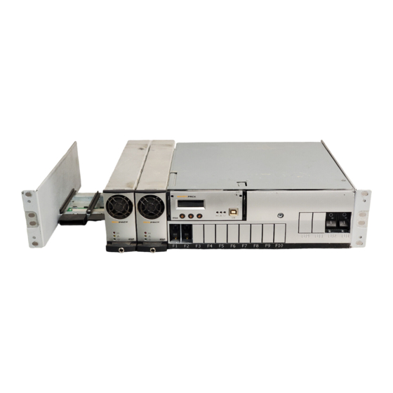
Installing Smartpack and Rectifier Modules ( 3) Installation and Maintenance Details ⎯ Opening or Closing the Minipack Drawer Shelf ⎯ Mounting or Removing Minipack Blind Covers ⎯ Removing or Mounting Load MCBs ⎯ Configuring Priority and Non-Priority Load Circuits (5) Installation steps;... - Page 2 Battery string #1 Example of a typical Minipack PS system for DC power supply of telecom equipment. The system is supplied from an external AC mains supply, and is delivered in one power shelf for integration in existing cabinets (integrated). An external battery bank is to be connected.
-
Page 3: Controller & Modules
Handle in unlocked position Mounting or Removing Minipack Rectifier Modules 1. Unlock the module by using a screwdriver to loosen the locking screw Minipack rectifier 2. - Page 4 Installation Details Installation and Maintenance Details Opening or Closing the Minipack Drawer Shelf To access the Minipack distribution area, you have to open the Fastening screws sliding drawer shelf. Do following to open or close the drawer: for the drawer...
- Page 5 WARNING: Only one screw can be removed at a time. P=Priority Load Circuits NP =Non Priority Load Circuits Plugs for MCB1 F3-F10 Screw (Y6) F5-F10 Screw (Y7) F7-F10 Screw (Y24) F9-F10 Screw (Y25) Quick Start Guide Minipack PS System 356808.103, 1v2-2008-10...
-
Page 6: Installation Steps
Mechanical Installation Power is OFF! Carry out the following: CAUTION: When transporting cabinetized Minipack systems with mounted rectifier modules, ensure that support plates or structures are always mounted under the Minipack PSS subassemblies. Remove packaging and check equipment Device o Check you have received all the parts and correct documentation... - Page 7 10 AC Connections o Check AC configuration: the external AC supply consists of 3 single phase mains feed and earth (PE) Minipack drawer shelf slid out in the maintenance position o Connect the AC Earth wires (PE) to the terminals X5:1-2 (PE) o Connect the AC input cables to the terminals X5:3-4, 5-6, 7-8.
- Page 8 Installation Location of Components, GA drawing The drawings show the location of components in Minipack PS Systems. Or refer to specific drawings included with your system. CAN1 Plastic Protective Cover for CAN bus communication with rectifiers (to Smartpack rear) AC Terminals...
- Page 9 Installation Connections, Factory Settings, etc The schematic shows the connection terminals in Minipack PS Systems. Or refer to specific drawings included with your system. Minipack PS System, Integrated If the 3ph AC Input Connection Kit, part 228898 or 238394 is used, follow the kit’s connection guide.
-
Page 10: Pre-Start Check
After the ”Pre-start Check” is performed, you can begin with stage II. During the stage, you will switch ON the Minipack PSS — while the batteries and load are disconnected ⎯ then measure the output voltage, and adjust it if required. Carry out the following:... - Page 11 6. Connect the a PC to the PS system (to facilitate operation) o Plug a standard USB A-B cable between the PC and the Smartpack controller o Start PowerSuite on the PC; select: Start > All Programs > Eltek Valere> PowerSuite Refer to chapter “...
-
Page 12: Operation
Smartpack control unit LED Lamp (yellow) Smartpack Control Unit — front keys, display Minipack Rectifier Module — front panel Power LED is OFF (mains unavailable), Flashing Display: is in Status Mode (displays the system’s (controller accessing information) or ON (powered). - Page 13 Smartpack (My Computer/ Properties/ Hardware/ Device Manager) and configure PowerSuite to communicate via this COMx (read the instructions in the installation CD). PowerSuite’s newest version is always available on our FTP server. Call your Eltek Valere’s contact person. Quick Start Guide Minipack PS System...
-
Page 14: Can Bus Termination
ID numbers formatted in italics (column 15 and 16 and range 65-78) are not available due to software constraints. For DIP switch configuration, refer to chapter “CAN Bus Nodes”, page 24. The figure shows a Minipack DC power system expanded with 3 CAN nodes to implement additional digital inputs, relay outputs or similar functionality. - Page 15 2024398. CAREFUL: Minipack systems using 48V-400W rectifiers may also use the recommended external breakers specified in the 800W Rectifiers table above, even though smaller breakers could be employed. For more information, read document 2028364...
- Page 16 Mains Feeds versus Rectifier ID Mains Monitoring The Minipack system is fed with 3 One-phase 230VAC Mains input circuits. Each input circuit is internally connected to feed 2 rectifiers, in such a pattern that loads the 3 circuits evenly. If your system is supplied from a 3-phase Mains input circuit, the use of a 3ph AC Input Connection Kit, part 228898 or 238394, is required.
-
Page 25: Battery Monitoring
Battery Block, Battery String and Battery Bank Battery Block (12V) Battery String #1 (48V)Batt. — (-48V) Outer Terminal Block1 Block3 Block4 Battery String #2 Intercell Links 48V Battery Bank 0V Outer (48V) Terminal Quick Start Guide Minipack PS System 356808.103, 1v2-2008-10... - Page 26 PowerSuite will then refer — — to the correct battery string. (-48V) Outer (-48V) Outer Terminal Block1 Block3 Block4 Terminal Block1 Block3 Block4 Intercell Links Intercell Links 0V Outer 0V Outer Terminal Terminal Quick Start Guide Minipack PS System 356808.103, 1v2-2008-10...
- Page 27 Always connect Battery Monitor with ID#<33> to battery strings 1 (lowest), 2, 3 and 4. Then Battery Monitor with ID#<34> to string 5, 6, 7 and 8. And so on. PowerSuite will then refer to the correct battery string. Quick Start Guide Minipack PS System 356808.103, 1v2-2008-10...
- Page 28 X3: 9-10) Temperature sensor The Temperature Sense Kits may also be connected directly to the Smartpack controller’s CON3 or CON4, if these connectors are unused. Battery Interface Card, Art. 200576 Quick Start Guide Minipack PS System 356808.103, 1v2-2008-10...
- Page 29 Alarms & Monitoring Standard Alarm Relays & Digital Inputs Connections Standard Relays & Digital Inputs The alarm outputs in Minipack systems use the Fail-Safe Operation Mode (relay coils energized in the system’s Normal Mode Relay X normal operation mode). When the system is in alarm mode, (Energized coil) the alarm relay coils are de-energized.
- Page 30 (fail-safe mode). The relay outputs are preprogrammed Relay 6 Alarm Circuit 6 from factory (Factory Settings). Rectifier Alarm (Customer Connections) 1.5 mm , max. wire section Quick Start Guide Minipack PS System 356808.103, 1v2-2008-10...
-
Page 31: Internal Connections
CON5, on the controller’s rear panel. Using a standard 15 pins D-Sub cable, the signals on CON5 are routed to the Minipack system’s main circuit board. See the figure in this section for an overview of the signals on CON5,... - Page 32 Monitor is the wire section last node in the CAN port 1&2 CAN bus RJ45, 8 pins Built-in Battery Temperature Sensor Read also the “Installation Guide Battery Monitor CAN Node”, document 351507.033. Quick Start Guide Minipack PS System 356808.103, 1v2-2008-10...
- Page 33 OFF⎯ON ⎯OFF⎯ON – Input Circuit 8 Sense Input switch’s binary ON ⎯ON ⎯OFF⎯ON Monitor value plus 49 OFF⎯OFF⎯ON ⎯ON Monitor 1.5 mm , max. (Customer Connections) Monitor ON ⎯OFF⎯ ON ⎯ON wire section Quick Start Guide Minipack PS System 356808.103, 1v2-2008-10...
-
Page 34: Dip Switches
Fan Speed Control 2 to the DIP Monitor OFF⎯ON ⎯OFF⎯ON switch’s binary ON ⎯ON ⎯OFF⎯ON Monitor 1.5 mm , max. value plus 81 (Customer Connections) Monitor OFF⎯OFF⎯ON ⎯ON wire section Monitor ON ⎯OFF⎯ ON ⎯ON Quick Start Guide Minipack PS System 356808.103, 1v2-2008-10... - Page 35 Quick Start Guide Minipack PS System 356808.103, 1v2-2008-10...
- Page 36 Quick Start Guide Minipack PS System 356808.103, 1v2-2008-10...
- Page 39 Quick Start Guide Minipack PS System 356808.103, 1v2-2008-10...
- Page 40 This product marked Copyright © Eltek Valere, 2008 complies with all current requirements This document may be changed without notice for relevant standards and directives. Art. No. 356808.103, Issue 1.2, 2008 Oct Published 2008-10-29 www.eltekvalere.com Headquarters: Eltek Valere Eltek Valere 1303 E.
Need help?
Do you have a question about the Minipack and is the answer not in the manual?
Questions and answers