Table of Contents
Advertisement
Quick Links
Download this manual
See also:
User Manual
Advertisement
Table of Contents

Subscribe to Our Youtube Channel
Related Manuals for Vdwall LVP8601


Summary of Contents for Vdwall LVP8601
- Page 1 LVP8601 LED Multi-window Sync Processor User Manual 1 / 42...
-
Page 2: Table Of Contents
Content Chapter 1: Safety precautions -------------------------------------------3-3 Chapter 2: Item list --------------------------------------------------------------4-4 Chapter 3: Hardware connection 1. System framework introduction------------------------------------------5-5 2. Rear view----------------------------------------------------------------------5-5 3. Port description --------------------------------------------------------------5-6 4. Connection diagram---------------------------------------------------------6-6 5. Specifications -----------------------------------------------------------------7-7 6. Dimension ---------------------------------------------------------------------8-8 Chapter 4: Front panel 1. Button instruction ------------------------------------------------------------8-10 Chapter 5: Function introduction 1. -
Page 3: Chapter 1: Safety Precautions
Chapter 1: Safety precautions Danger! There is high voltage in the processor, to prevent any unexpected hazard, unless you are a maintenance personnel, please do not open the cover of the device. Warning! a) This device shall not encounter water sprinkle or splash, please do not place anything containing water on this device. -
Page 4: Chapter 2: Item List
Chapter 2: Item list Please unpack the product with care, and then check whether all the following items are included in the package. If anything is found missing, please contact the dealer. Standard accessories The accessories supplied with this product may differ from the following pictures, but they are applicable for the regions where you live. -
Page 5: Chapter 3: Hardware Connection
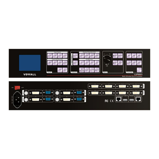
2. Rear view 3. Port description 1) Input ports LVP8601 maximally supports 4 PCS of input cards (In-A, In-B, In-C, In-D) and each card supports 4 input signals. The port description is as follows: Port Description... -
Page 6: Connection Diagram
2) Output ports LVP8601 maximally supports 2 PCS of output cards (Out-K, Out-L) and each card supports 4 DVI outputs. The port description is as follows: Port Description 8X DVI output ports (for connecting to Out1-Out4 sending cards or monitors) -
Page 7: Specifications
5. Specifications Inputs 4×Video 4×VGA(RGBHV) Type/Number 4×DVI(VESA/CEA-861) 4×SDI (SDI/HD-SDI/3G-SDI) Video Standard PAL/NTSC Composite Video 1V (p_p)/ 75Ω Amplitude / Impendence ≤1920×1200_60Hz VGA Format PC (VESA) Amplitude R、G、B = 0.7 V (p_p) / 75Ω Impendence ≤1920×1200_60Hz PC (VESA) DVI Format ≤1080p_60Hz HDMI-1.3 (CEA-861) 480i_60Hz SMPTE 259M... -
Page 8: Dimension
6. Dimension Chapter 4: Front Panel 1. Button instruction 1) Input Cards (In-A, In-B, In-C, In-D): stand for 4 input cards accordingly, when pressing a button to select a card, if the red light of the indicator is on, it means the operation of the current input card is valid. 2) Input Card Sources (Video, VGA, DVI, SDI): input signal select, when 8 / 42... - Page 9 selecting an input signal, if the green light of the indicator is on, it means the signal is available, otherwise the light will flicker. 3) PIP: turn on or off the picture-in-picture function. If the indicator is on, it means signals are selected, otherwise it will flicker. The signal for sub picture (PIP) can be selected by pressing a button in “Input Card Sources”...
-
Page 10: Chapter 5: Function Introduction
Chapter 5: Function introduction LVP8601 can maximally support 4 pcs (In-A ,In-B, In-C, In-D) of video input cards (each card includes 1 X SDI, 1 X DVI, 1 X VGA and 1 X Video) or 2 pcs of single DVI straight-through cards and 2 pcs of output cards. - Page 11 Out1 Out2 Out3 Output Out4 Matrix In-A Output(Out-K) In-B In-C Out1 In-D Out2 Main Out3 Matrix ( MatrixK Output Out4 /MatrixL) Matrix Main Board Output(Out-L) As shown in the figure, CH1, CH2, CH3 and CH4 stand for 4 internal image output channels or image layers in the output card. In the control software interface and on the panel buttons or OSD display, those channels or layers will be all marked as CH1, CH2, CH3 and CH4;...
-
Page 12: Configuration Mode 1
select the mode according to their specific requirements. 1. Configuration mode 1 Out1 Out 2 Out 3 Output Out 4 Matrix Config_Mode1 In this mode, Out1=CH1 Out2= CH2 Out3 = CH3 Out4 = CH4 This means: Output port 1 (Out1) outputs image from image layer 1 (CH1) Output port 2 (Out2) outputs image from image layer 2 (CH2) Output port 3 (Out3) outputs image from image layer 3 (CH3) Output port 4 (Out4) outputs image from image layer 4 (CH4) - Page 13 input (In1, In2, In3, In4) and in this way we can have many derivation modes to realize different processing and display effects. For example: Out1 Out 2 Out 3 Output Out 4 Matrix Config_Mode1 derivation mode 1 Out1 Out 2 Out 3 Output Out 4...
-
Page 14: Configuration Mode 2
In this mode, input images can be cropped as output images for Out1, Out2 and Out3. By using this mode, the LVP8601 will be mainly used as a switcher of 4 inputs and 3 outputs with seamless or fade effect. -
Page 15: Configuration Mode 3
In this mode, we can also press “Fade” to set the time for switching of image layers so as to realize seamless switching or fade effect. By using this mode, LVP8601 will be used for triple-image display from single output plus single-image preview or as a switcher of single output plus single-image preview. -
Page 16: Configuration Mode 4
Out1 and Out2 are blended into a complete one and the display is completely synchronous. By using this mode, LVP8601 will be used for pixel-to-pixel sync image mosaic and the maximal resolution supported is 4K x 2K. 16 / 42... -
Page 17: Configuration Mode 6
5. Configuration mode 6 Out1 Out 2 Out 3 Output Out 4 Matrix Config_Mode6 In this mode: Out1= CH1 + CH2 + CH3 + CH4 This means: Out1 outputs the image generated by four image layers overlapped (CH1, CH2, CH3, CH4); There are no outputs from Out2, Out3, Out4;... -
Page 18: Configuration Mode 7
By using this mode, LVP8601 will be used as a quad-display processor or a switcher of single output with fade effect. 6. Configuration mode 7 Out1 Out 2 Out 3 Output Out 4 Matrix Config_Mode7 In this mode: Out1= CH1 + CH2... -
Page 19: Chapter 6: Basic Operation Introduction
In this mode, we can also press “Fade” to set the time for switching of image layers so as to realize seamless switching or fade effect. By using this mode, LVP8601 will be used as a dual-display processor of dual outputs or a dual-output switcher. It can be... -
Page 20: Text Overlay Setup Of Input Cards
3. Text overlay setup of input cards Press “Text” and select “SDI, DVI, VGA or Video” as the signal for Text overlay. Press “In-A, In-B, In-C or In-D” to select an input card for operation. 4. Setup of the correspondence between output channels and input channels for output cards When the indicator for “Matrix”... -
Page 21: Configuration Mode Setup
Out-L Display Mode:M1 INV.METH.:Single Card INV.SEQ.:Overlap–> Matrix -> Size -------------------------------------- -------------------------------------- Press “M+” to enter the menu of “Display Mode Setup”,“↑” to select the invocation mode of display mode and “↓” to select the invocation sequence, “ ” to quit the menu. The invocation mode of display modes is “Single Card/Single Card+Input Card/Double Card/Double Card+Input Card”... -
Page 22: Brightness Setup
Tips -------------------------------------- Data will reset Press <OK> to reset Press <return> to cancel -------------------------------------- Notice: to change the configuration mode will lead to reset of the data of output cards, please be careful. 9. Brightness setup The adjusting range of brightness is 0-32,“0” stands for the lowest brightness, press “Brt+”... - Page 23 12. Check system information Press “Info” to enter the menu of system information, and press then “↑↓”to turn the page and “ ” to quit. The menu is as follows: System Info -------------------------------------- Model: LVP8601 Version: V0.3.6 192.168.1.10 Mask: 255.255.255.0 Gate:...
-
Page 24: Chapter 7: User Settings
Chapter 7: User settings User settings, which are used to setup the overall system, consist of 3 parts: input card, output card and the system. On the default menu, when system starts, press “Setup” to enter the menu of “User Settings” and “↑,↓” to select settings, press “OK”... -
Page 25: Input Card Setup
Input Card Main Setup In-A -------------------------------------- 1.Hori Width 666 -> 888 2.Hori Start 3.Vert Height 4.Vert Start -------------------------------------- 2) Set the size and location of PIP On the menu of “Input Card Setup”, press “↑,↓” to select “PIP Setup” and “OK” to enter the sub menu. In-A Setup -------------------------------------- 1.Main Setup... - Page 26 Setup” and “OK” to enter the sub menu. In-A Setup -------------------------------------- 1.Main Setup 2.PIP Setup 3.Image Setup 4.Advanced Setup -------------------------------------- Press “↑,↓” to select the setting, turn the knob to adjust and then press “OK” to confirm. Input Card Image Setup In-A -------------------------------------- 1.Brightness...
- Page 27 In-A Setup -------------------------------------- 1.Main Setup 2.PIP Setup 3.Image Setup 4.Advanced Setup -------------------------------------- Text settings On the menu of “Input Card Advanced Setup”, press “↑,↓” to select the setting, turn the knob to adjust and then press “OK” to confirm. Input Card Advance Setup In-A --------------------------------------...
- Page 28 system data to be consistent with that of the new input cards. To change input cards by users themselves is not recommended. Reset input card On the menu of “Input Card Advanced Setup”, press “↑, ↓” to select “Reset Data” and “OK” to confirm. Input Card Advance Setup In-A --------------------------------------...
- Page 29 Setup -------------------------------------- 1.Input Card Setup 2.Output Card Setup 3.System Setup -------------------------------------- 1) Set the size and location of input image for output card On the menu of “Output Card Setup”, press “↑,↓” to select “Input Image Setup” and “OK” to enter the sub menu. Out-K Setup -------------------------------------- 1.Input Image Setup...
- Page 30 Out-K Setup -------------------------------------- 1.Input Image Setup 2.Output Image Setup 3.Border Setup 4.Advanced Setup -------------------------------------- Press “↑,↓” to select the setting, turn the knob to adjust the value and then “OK” to confirm. Output Card Output Image Setup Out-K/M1/CH1 -------------------------------------- 1.Hori Width 666 ->...
- Page 31 Output Border Setup Out-K/CH1 -------------------------------------- 1.Border 2.Border R 3.Border G 4.Border B 5.Border Size -------------------------------------- 4) Clock Setup (only in configuration mode 4) On the menu of “Output Card Setup”, press “↑, ↓” to select “Clock Setup” and “OK” to enter the sub menu. Out-K Setup -------------------------------------- 1.Input Image Setup...
- Page 32 5) Edge blending setup (only in configuration mode 4) On the menu of “Output Card Setup”, press “↑, ↓” to select “Edge Blending Setup” and then press “OK” to enter the sub menu. Out-K Setup -------------------------------------- 1.Input Image Setup 2.Output Image Setup 3.Clock Setup 4.Edge Blending Setup 5.Advanced Setup...
- Page 33 On the menu of “Output Card Advanced Setup”, press “↑, ↓” to select “Config Mode” and “OK” to enter the sub menu. Output Card Advanced Setup Out-K -------------------------------------- 1.Config Mode 6 –> 7 2.Preview 3.Auto Detect 4.CH Reset 5.Refresh Data 6.Reset Data -------------------------------------- On the sub menu of “Config Mode”, press “OK”...
- Page 34 Notice: when “Preview” is on, only Out1 will output a quad-image preview and there will be no outputs from Out2, Out3 or Out4. Auto detect of signals for output cards On the menu of “Output Card Advanced Setup”, press “↑, ↓” to select “Auto Detect”, turn the knob to adjust and then press “OK”...
- Page 35 Output Card Advanced Setup Out-K -------------------------------------- 1.ConfigMode 2.Preview 3.AutoDetec 4.CH Reset 5.Refresh Data 6.Reset Data -------------------------------------- Notice: sometimes when users change output cards themselves, the data of new output cards might be inconsistent with that of the system. “Refresh Data” will then update the system data to be consistent with that of the new output cards.
- Page 36 Notice: sometimes when users change output cards by themselves, the data of new output cards might be inconsistent with that saved by the system. “Reset data” will restore the data of new input cards to the factory default. The operation is only valid for a single output card, so it won’t affect the data of other output cards.
- Page 37 IP Setup -------------------------------------- 1.Address1 192 -> 190 2.Address2 3.Address3 4.Address4 -------------------------------------- 2) Subnet mask address On the menu of “System Setup”, press “↑,↓” to select “MASK Setup” and “OK” to enter the sub menu. System Setup -------------------------------------- 1.IP Setup 2.MASK Setup 3.GATE Setup 4.MAC Setup 5.MatrixK Setup...
- Page 38 System Setup -------------------------------------- 1.IP Setup 2.MASK Setup 3.GATE Setup 4.MAC Setup 5.MatrixK Setup 6.MatrixL Setup 7.Advanced Setup -------------------------------------- Press “↑,↓” to select the setting, turn the knob to adjust and then press “OK” to confirm. GATE Setup -------------------------------------- 1.Address1 2.Address2 3.Address3 4.Address4 --------------------------------------...
- Page 39 MAC Setup -------------------------------------- 1.Address1 2.Address 2 3.Address 3 4.Address 4 5.Address 5 6.Address 6 -------------------------------------- 5) Matrix setup for Out-K (MatrixK) On the menu of “System Setup”, press “↑,↓” to select “MatrixK Setup” and “OK” to enter the sub menu. System Setup -------------------------------------- 1.IP Setup...
- Page 40 System Setup -------------------------------------- 1.IP Setup 2.MASK Setup 3.GATE Setup 4.MAC Setup 5.MatrixK Setup 6.MatrixL Setup 7.Advanced Setup -------------------------------------- Press “↑,↓” to select the setting, turn the knob to adjust and then press “OK” to confirm. MatrixL Setup -------------------------------------- 1.L-In1 In-A 2.L-In2 In-B 3.L-In3...
- Page 41 On the menu of “Advanced Setup”, press “↑,↓” to select “Language”, turn the knob to adjust and then press “OK” to confirm. System Advanced Setup -------------------------------------- 1.语言 Language English 2.Out Format 1920x1080_60Hz 3.Reset Data -------------------------------------- Output resolution On the menu of “Advanced Setup”, press “↑,↓” to select “Out Format” and then turn the knob to adjust.
-
Page 42: Chapter 8: Copyright Information
Normally it is not suggested to use. Chapter 8: Copyright information The copyright of this manual is owned by SHENZHEN VDWALL CO.,LTD., unless with prior consent of VDWALL, nobody is permitted to copy or use any part or all of the information contained herein.
Need help?
Do you have a question about the LVP8601 and is the answer not in the manual?
Questions and answers