Table of Contents
Advertisement
Advertisement
Table of Contents

Related Manuals for Vdwall LVP7000 Series


Summary of Contents for Vdwall LVP7000 Series
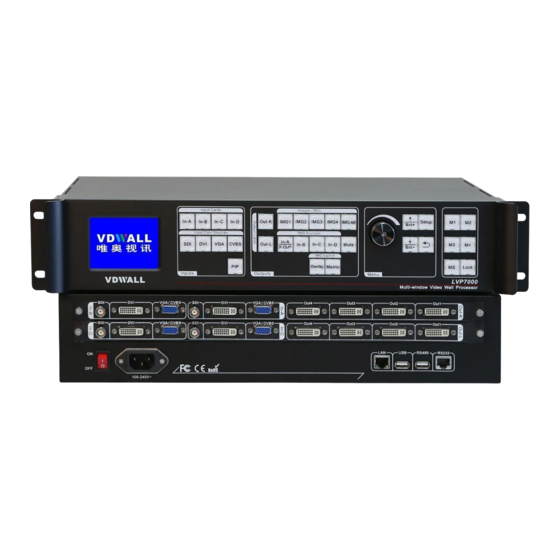
- Page 1 LVP7000 Series LED Multi-Window Video wall Processor User Manual...
-
Page 2: Table Of Contents
LVP7000 series user manual Contents Chapter 1: Safety precautions..........04 Chapter 2: Packing list............05 Chapter 3: Hardware connection.........06 3-1 Rear panel signal port picture......06 3-2 Port description .............06 3-3 Hardware connection diagram ......08 3-4 Technical specification ..........09 3-5 Installation dimension drawing......11 Chapter 4: Frontal panel button description ....13... - Page 3 LVP7000 series user manual instruction ..................50 8-1 System random adjustment and verification..50 8-2 Data recovery............52 8-3 PC software import and export……….....53 Chapter 9: Mode instruction…..........58...
-
Page 4: Chapter 1 Safety Precautions
LVP7000 series user manual Chapter 1 Safety precautions Danger ! There is high voltage in the processor, to prevent any unexpected hazard, unless you are a maintenance personnel, please do not open the cover of the device. Warning ! 1) This device shall not encounter water sprinkle or splash, please do not place anything containing water on this device. -
Page 5: Chapter 2 Packing List
LVP7000 series user manual 5) Do not place the device near any water source or anywhere damp. 6) Do not place the device near any radiator or anywhere under high temperature. 7) To prevent rupture or damage of power cords, please handle and keep them properly. -
Page 6: Chapter 3 Hardware Connection
LVP7000 series user manual (Quantity depends on (Quantity depends on input card quantity) output card quantity) VGA transform VGA+RCA 1.5m RS232-RJ45 cable X (Quantity depends on 1.5m USB cable X 1 input card quantity) HDMI to DVI-D adapter X 2... - Page 7 LVP7000 series user manual 1. Video signal input LVP7000 can assemble maximum 4 video input cards, the series numbers are In-A、In-B、In-C、In-D. every video input card support 4 channels of signal input, signal input port as the table below: Ports Description...
- Page 8 LVP7000 series user manual Ports Description 4 channels of DVI output port, Out1 ~ Out4 used to connect LED sending card or monitor, Out1 is DVI-I port which includes VGA format signal output. 3. Communication port Ports Description Local area...
-
Page 9: Hardware Connection Diagram
LVP7000 series user manual 3-3 Hardware connection diagram Picture 3-2 hardware connection diagram 3-4 Technical specification... - Page 10 LVP7000 series user manual Input signal index 4×CVBS 4×VGA(RGBHV) Quantity / type 4×DVI(VESA /CEA-861) 4×SDI(HD-SDI/3G-SDI) Composite video PAL/NTSC system Composite Video Amplitude / 1V(p_p)/ 75Ω Impendence VGA format PC(VESA) ≤1920×1200_60Hz VGA Amplitude / R、G、B = 0.7 V(p_p)/ 75Ω Impendence PC(VESA)...
- Page 11 LVP7000 series user manual Overall power ≤100W consumption Environment 0-45 ℃ temperature Environment humidity 15-85% Product size 483( Length ) x 300( Width ) x 89( Height )mm Packing size 540( Length ) x 400( Width ) x 180( Height )mm Weight G.W.:9Kg, N.W.:5Kg...
-
Page 12: Installation Dimension Drawing
LVP7000 series user manual 3-5 Installation dimension Picture 3-5a installation dimension drawing... - Page 13 LVP7000 series user manual RS232 connection wires, wires order Note: 1. A is RS232 female connector 2. B is RJ45 connector 3. Accord with emergency decree, The wires must be soft: Picture 3-5b RS232 connection wires, wires order...
-
Page 14: Chapter 4 Frontal Panel Button Description
LVP7000 series user manual Chapter 4 Frontal panel button description 4-1 Frontal panel button sketch map Picture 4-1 frontal panel button sketch map Input card function button Output card function button Setup button Display mode button 1. Input card selection button Input card selection button used to select input card. - Page 15 LVP7000 series user manual SDI、DVI、VGA、CVBS Note: press VGA button continually processor will adjust VGA signal automatically. 3. PIP on-off button Input card PIP on-off button, after opening the green indicator light on the button flicker, waiting for select PIP signal source, under the menu “Input Card Sources”...
- Page 16 LVP7000 series user manual Output image selection button, when select some output image, the green indicator light on relative button lit up normally, this moment you do relative operation or setup to the output image. IMG All indicate select all output image.
- Page 17 LVP7000 series user manual 8. Output image overlay on-off and switch time button (Overlay/Fade) When several image furl together, every image from top layer to bottom layer has overlay order. Overlay is multi image overlay switch on-off button, after opening the red...
- Page 18 LVP7000 series user manual IMG All)to select output image, then through press output image signal source button to select relative signal source. 10. Setup buttons Setup button: set processor function parameters. Setup、↑、 ↓、Knob、 Setup:Press to enter setup menu ↑、↓:Press to select upper or down setup option Knob :...
- Page 19 LVP7000 series user manual processor displays current setup and information. Press ↑ or ↓ can check the last or next option, press button to exit the interface. 13. Display mode buttons(M1,M2,M3,M+,MS) : Display mode buttons, from 1 to 16 total 16 sets, display mode 1, 2 and 3 are directly selected by press M1,M2 and...
-
Page 20: Chapter 5 Application Mode And Function Introduction
LVP7000 series user manual D: matrix configuration of output card 14. Lock button Lock button (Lock) , buttons lock function button, when lock is open the red indicator light on the button lit up, except Lock , another buttons are not available, press Lock button three times continually to unlock, the red indicator light on the button is closed. - Page 21 LVP7000 series user manual In-A In-A Out1 IMG1 In-B IMG2 Out2 In-B In-C IMG3 Out3 In-C In-D Output In-D IMG4 Out4 Matrix Output card Out-K K.Out1 In-A Out1 IMG1 In-B IMG2 Out2 In-C IMG3 Out3 In-D Output IMG4 Out4 Matrix...
-
Page 22: Appm1 (4 Channels Splicing Or 4:4 Matrix)
LVP7000 series user manual card; According to different application, LVP7000 output card setup has 4 kids of different application mode (AppM), AppM1 (4 channels splicing 4:4 matrix), AppM2 (4:2 seamless switching), AppM7 (2 channels dual image), AppM6 (4 images), according to customer’s project requirement to select relative application mode. - Page 23 LVP7000 series user manual Output port2 (Out2) outputs image2 (IMG2)’s image Output port3 (Out3) outputs image3 (IMG3)’s image Output port4 (Out4) outputs image4 (IMG4)’s image Under the application mode, press Matrix button to open matrix switch mode, then every one of output image (IMG1、IMG2、IMG3、IMG4)can select anyone of input...
-
Page 24: Appm2(4:2 Seamless Switching)
LVP7000 series user manual 5-2 AppM2(4:2 seamless switching) In-A IMG1 Out1 In-B IMG2 Out 2 In-C IMG3 Out 3 Output In-D IMG4 Out 4 matrix Out3=Out1 Out4=Out2 AppM1 ( 4:2 seamless switching) Picture 5-2a LVP7000 application mode2 sketch map Under the application mode Out1=IMG1,... - Page 25 LVP7000 series user manual Out1 and Out2 port) 5-3 AppM7(2 channels dual images) In-A IMG1 Out1 In-B IMG2 Out 2 In-C IMG3 Out 3 Output In-D IMG4 Out 4 matrix Out3=Out1 AppM7(2 channels dual images) Out4=Out2 Picture 5-3a LVP7000 application mode3 sketch map...
- Page 26 LVP7000 series user manual card signal (In-A、In-B、In-C、In-D). Out1 and Out2 separately output the image of 2 output images overlay compound image. Press Overlap button to open layer overlay mode, press output image button directly to let relative output image display on top layer.
- Page 27 LVP7000 series user manual In-A IMG1 Out1 In-B IMG2 Out 2 In-C IMG3 Out 3 Output In-D IMG4 Out 4 matrix AppM6(4 images) Out2= Out3=Out4=Out1 Picture 5-5a LVP7000 application mode6 sketch map Under the application mode, Out1=IMG1+ IMG 2+ IMG 3+ IMG 4,...
-
Page 28: Chapter 6 User Basic Operation Instruction
LVP7000 series user manual fade in fade out switching effect. (fade in fade out switch effect is only valid for Out1 port) Otherwise, when output card work under the application mode, can call display mode M16 directly to achieve 4 images preview function. -
Page 29: Input Card Operation
LVP7000 series user manual In-A(Input Card) Main Source: PIP/TEXT: Out-L(Output Card) Display Mode=M1 To Output: Out1 Out2 Out3 Out4 Out IMG: IMG1>IMG2>IMG3>IMG4 In Card: In-A In-A In-A In-A AppM1(4 Outputs Splitter/4:4 Matrix) L.Out1=IMG1 L.Out2=IMG2 L.Out3=IMG3 L.Out4= IMG4 In-A(Input Card) Main Source:... - Page 30 LVP7000 series user manual input card signal source button(SDI、 DVI、 VGA、 CVBS) to switch signal source. 2. Input card PIP operation Press input card button (In-A、In-B、In-C、In-D) , then press PIP button to enter PIP ready state, then press input card signal source button(SDI、 DVI、 VGA、 CVBS)...
- Page 31 LVP7000 series user manual 4. VGA input signal automatic adjustment When the input source of current input card is valid VGA input, press VGA button to enter VGA automatic adjustment confirmation menu, press VGA button again to adjust VGA signal, press to exit menu.
-
Page 32: Output Card Operation
LVP7000 series user manual 6-2Output card operation Under user operation interface, the operation content of output card include: set the relative relationship of output image and input card signal, output image overlay mode operation, switch time of output image overlay mode, display mode setup, application mode setup and brightness setup. - Page 33 LVP7000 series user manual matrix switch mode, firstly press Out-K or Out-L button to select a output card, then press image buttons(IMG1、 IMG 2、IMG 3、IMG 4、IMG All)to select output image, then press image signal source button(In-A、 In-B、 In-C、 In-D)to select the input channel you need.
- Page 34 LVP7000 series user manual output card, then press image button (IMG1、IMG 2、 IMG 3 、 IMG 4 )can change the overlay relationship of output image, the image be selected become on top layer. Note: the function is only valid in 2 channels dual image, multi-image application mode.
- Page 35 LVP7000 series user manual display mode 4 to 16 need to be called in mode call menu, press M+ button to open mode menu, rotate knob to select mode, meantime the indicator light on the button lit up. MS is display mode copy button, can copy the parameters status in one display mode to another display mode.
- Page 36 LVP7000 series user manual Current Display Mode: Available Card: Out-K+Out-L -------------------------------------- ------------------------------------- Picture 6-2a LCD interface: display mode switch 5. Output card application mode setup On front panel press Setup button to enter “user setup” menu, press ↓ button to select “Output Card Setup”...
-
Page 37: Another Function Operation
LVP7000 series user manual increase, and press Brt- button to decrease. For ensure complete output image grayscale, normally set the output brightness value be 32, rotate knob to select single or dual card to adjust brightness. Out-K+Out-L Brightness -------------------------------------- 1. Brightness -------------------------------------- Picture 6-2b LCD interface:... - Page 38 LVP7000 series user manual under lock status, to prevent conflict between remote operation and button operation only LAN, RS232 and USB communication are available. When button is lock status, press Lock button 3 times continually to exit. Button lock --------------------------------------...
- Page 39 LVP7000 series user manual System Info -------------------------------------- Mode: LVP7000 Version: V0.1.2 Resolution: 1920x1080_60Hz Made Date: 2017-04 -------------------------------------- ↑/↓To Page To Exit Picture 6-3b LCD interface: system information System Info -------------------------------------- 192.168.1.8 MASK: 255.255.255.0 GATE: 192.168.1.1 MAC: 76-64-77-1A-2B-3A Device ID: -------------------------------------- ↑/↓To Page...
- Page 40 LVP7000 series user manual Out - L -------------------------------------- Out Format: 1920x1080_60Hz Version: V1.1.3 -------------------------------------- ↑/↓ To Page To Exit Picture 6-3e LCD interface: system information System Random Checksum -------------------------------------- In-A:AF8F0E8E0D8D0C8 AF8F0E8E0D8D0C8 In-B:BF8F0E8E0D8D0C8 BF8F0E8E0D8D0C8 In-C:CF8F0E8E0D8D0C8 CF8F0E8E0D8D0C8 In-D:DF8F0E8E0D8D0C8 DF8F0E8E0D8D0C8 Picture 6-3f LCD interface: system information...
-
Page 41: Chapter 7 User Setup Menu Instruction
LVP7000 series user manual Chapter 7 User setup menu instruction User setup menu is about whole processor setup, total divide to be 4 modules, respectively are input card setup, output card setup, system setup and language setup. Setup -------------------------------------- Input Card (1.1-4.2)... -
Page 42: Input Card Setup
LVP7000 series user manual 7-1 Input card setup After system starting up, press Setup button to enter user setup menu, in the menu through press ↑,↓ button to select Input Card Setup(1.1-4.2) , press knob (OK button) to enter the setup menu as below. - Page 43 LVP7000 series user manual change current parameter, press knob (OK button) to save parameter. 1.PIP Setup In-A -------------------------------------- 1.1 PIP Image Width 640 -> 645 1.2 PIP Image Height 1.3 PIP Image H_Start 1.4 PIP Image V_Start 1.5 Main Image Width 1920 1.6 Main Image Height...
- Page 44 LVP7000 series user manual 2. TEXT Setup In-A -------------------------------------- 2.1 Text Overlay 2.2 Text Source 2.3 Text Mode <Threshold 2.4 Text Threshold R 2.5 Text Threshold G 2.6 Text Threshold B Picture 7-1c LCD interface: text setup 3. Image quality Image quality menu is used to set the brightness, contrast and color.
- Page 45 LVP7000 series user manual Picture 7-1d LCD interface: image quality setup 4. input card advanced setup 4. Advanced In-A -------------------------------------- 4.1 Resume Data OK To Apply 4.2 Reset Dadta OK To Apply -------------------------------------- Resum Data: Write System Data To In-A Picture7-1e LCD interface:...
-
Page 46: Output Card Setup
LVP7000 series user manual Setup method: press input card button (In-A,In-B, In-C, In-D) to select input card, press ↑,↓ button to select relative setup option, press OK button, then press OK button in the menu of data will reset reminder. - Page 47 LVP7000 series user manual Output Card Setup(E.1-H.7) Out-K -------------------------------------- E. IMG Setup >> F. Output Clock >> G. Border Setup >> H. Advanced >> Picture 7-2a LCD interface:Output card setup 1. IMG setup E.IMG Setup Out-K/M1/IMG3 -------------------------------------- E.1 Out Width 1920 ->...
- Page 48 LVP7000 series user manual button) to save parameter. E.IMG Setup Out-K/M1/IMG3 -------------------------------------- Mosaic Reference E.9 LED Total Width 3840 E.10 LED Total Height 2160 E.11 IMG3 Width 1920 E.12 IMG3 Height 1080 E.13 IMG3 H_Start E.14 IMG3 V_Start ->OK To Load E1-E8 Reference Picture 7-2c LCD interface:Splicing reference calculation...
- Page 49 LVP7000 series user manual press OK button, then in the menu of output card IMG data will be covered, press OK button, the current parameter in menu E.1-E.8 update as automatic calculation parameter, meantime the right side of every relative setup option displays the parameter value of calculation;...
- Page 50 LVP7000 series user manual F. Output Clock Out-L -------------------------------------- F.1 Frame Sync Picture 7-2e LCD interface:Output port configuration 3. Border setup(is only valid in AppM7 and AppM6) G. Border setup menu is used to set the color and border width of border of output image. Press ↑,↓ button to select relative setup menu option, rotate knob to change current parameter, press OK to save parameter.
- Page 51 LVP7000 series user manual 4. Output card advanced setup H. Advanced Out-K -------------------------------------- H.1 App.Mode AppM6 AppM6(4 Image Overlay) K.Out1=IMG1+IMG2+IMG3+IMG4 K.Out2=K.Out3=K.Out4=K.Out1 H.2 In-A/K.Out1 Selet In-A H.3 IMG Reset OK To Apply H.4 Resume Data OK To Apply H.5 Reset Data OK To Apply Picture 7-2g LCD interface:...
- Page 52 LVP7000 series user manual 2). In-A/K.Out1 selection LVP7000 can let the output image of K.Out1 connect to L card as the signal source of matrix switch, H.2 In-A/K. Out1 selection menu is used to set input source In-A or K.Out1 when L card matrix switch. After selection the menu, rotate knob to select signal needed, press OK button to save setup.
- Page 53 LVP7000 series user manual 4). Data recovery and data initialization H. Advanced Out-K -------------------------------------- H.1 App. Mode AppM6 H.2 In-A/K.Out1 Select In-A H.3 IMG Reset OK To Apply H.4 Resume Data OK To Apply H.5 Reset Data OK To Apply -------------------------------------- Reset Data:Init Out-K Data...
-
Page 54: System Setup
LVP7000 series user manual Out-L )to select output card, press ↑ , ↓ button to select relative setup menu option, press OK button, then in the reminder menu of data will reset, press OK button again. 7-3 System setup After system starting up, press Setup to enter user setup menu, in the menu trough press ↑... - Page 55 LVP7000 series user manual Communication -------------------------------------- 192.168.1.8 M.2 MASK 255.255.255.0 M.3 GATE 192.168.1.1 M.4 MAC 76:64:77:1D:2B:3C -------------------------------------- M.5 Device ID Picture 7-3b LCD interface: Communication parameter setup communication menu used communication parameter of network. In the menu, press ↓ button to select adjustment setup option, rotate knob to...
- Page 56 LVP7000 series user manual 2. System advanced setup N. Advanced -------------------------------------- N.1 Resolution 1920x1080_60Hz N.2 Out-K App. Mode AppM6 N.3 Out-L App. Mode AppM6 N.4 Reset Data OK To Apply Picture 7-3c LCD interface: System advanced setup In the menu can set the output resolution of...
-
Page 57: Language Setup
LVP7000 series user manual to recover the current output resolution and application mode be default status. Note: changing application mode will cause the user data in the output card cleaned, careful to use! 7-4 Language setup After system starting up, press Setup to enter user setup menu, in the menu through press ↑... -
Page 58: Chapter 8 System Maintenance And Relative Operation
LVP7000 series user manual Q. 语言/Language -------------------------------------- Q.1 语言/Language 中文 Picture 7-1a LCD interface:Output port configuration Chapter 8 System maintenance and relative operation instruction LVP7000 adopt inserting card structure design, and add system data recovery and random adjustment and verification function, PC software import and export function, very convenient for project maintenance. - Page 59 LVP7000 series user manual two data will change meanwhile. After changing output resolution and application mode, LVP7000 meantime will separately write a group of same random data to backboard system and relative input and output card, it is called system random checksum value. The value can through press OK button to enter system information menu to check.
- Page 60 LVP7000 series user manual As the picture above show about system random checksum value: 1. Every card has two checksum values, the first line is system checksum value, and the second line is the checksum of the card; 2. The first bit of checksum correspond to card, for example as K start, it indicates the data belong to K card;...
-
Page 61: Data Recovery
LVP7000 series user manual Tips -------------------------------------- In-A Data Error In-B Data Error Out-K Data Error -------------------------------------- Please reset Picture 8-1c LCD interface:Starting up error reminder 8-2 Data recovery After replacing new card or card has data error, we can write the original data we saved in system to relative card, to avoid set the parameters repeatedly, it is the function of data recovery. -
Page 62: Pc Software Import And Export
LVP7000 series user manual H. Advanced Out-K -------------------------------------- H.1 App. Mode AppM6 H.2 In-A/K.Out1 Select In-A H.3 IMG Reset OK To Apply H.4 Resume Data OK To Apply H.5 Reset Data OK To Apply -------------------------------------- Reset Data: Init Out-L Data Picture 8-2b LCD interface:Output card data recovery... -
Page 63: Chapter 9 Mode Instruction
LVP7000 series user manual Picture 8-3a PC software import and export Chapter 9 Mode instruction LVP7000 serials adopt insert card design method, the quantity of input card and output card depend on requirement to custom-make. The specific mode description as below:...
Need help?
Do you have a question about the LVP7000 Series and is the answer not in the manual?
Questions and answers