Table of Contents
Advertisement
Thank you very much for purchasing PI8600 Family Frequency Inverters. This family is
designed based on the experience of POWTRAN Company in the professional manufacture and
sale of the products, and suitable for general-purpose load machine.
This product adopts the advanced sensorless vector control technology, combined with China
local frequency inverter application features to achieve high-performance V/F control (dead-time
compensation + auto-torque upgrade + Slip Compensation) and high-performance non-sense vector
control, and high-performance speed sensorless vector control.
This product adopts the advanced sensorless vector control technology, combined with the
application of inverter technology in China features to achieve high-performance V/F control
(dead-time compensation + auto-torque upgrade + Slip Compensation) and high-performance non-
sense vector control, and high-performance speed sensorless vector control.
This User‟s Manual includes PI8600, the general purpose control F and G series.
F: FLOW LOAD
G: GENERAL LOAD
Please contact the local dealers or directly contact our company.
Please keep this user‟s manual in good condition, for it will be helpful to the repair,
maintenance, and applications in the future.
For information about other product, please visit our website: http://www.powtran.com.
Foreword
Advertisement
Table of Contents

Related Manuals for Powtran PI8600 G Series


Summarization of Contents
Inspection and Safety Precautions
Inspection After Unpacking
Checks after unpacking the inverter unit and its accessories.
Safety Precautions
Important safety measures to follow before and during operation.
Inverter Applications
General applications and specific considerations for using the inverter.
Installation and Standby Circuit
Conditions for Use
Environmental and operational conditions required for safe and effective use.
Installation Guidelines
Guidelines and diagrams for proper physical installation of the inverter.
Wiring Instructions
Explains the main and control circuit wiring requirements for the inverter.
Main Circuit Terminals
Details about the main circuit terminals and their functions.
Control Circuit Terminals
Details about the control circuit terminals and their functions.
Control Circuit Terminal Details
Further details on control circuit terminals and their specific functions.
Connection Precautions
Critical precautions to ensure safe and correct wiring connections.
Operation Keyboard and Interface
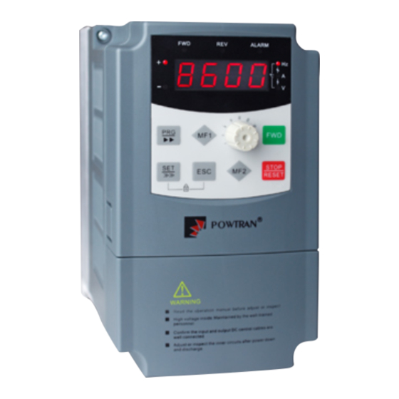
Operating Keyboard Overview
Overview of the inverter's operating keyboard and its layout.
Optional Keyboard Specifications
Details for the optional JP3E8600 keyboard layout and key functions.
Parameter Setting Examples
Step-by-step example of setting frequency parameters using the keyboard.
Parameter Upload to Keyboard
Procedure for uploading parameters from the inverter to the keyboard.
Resetting System Parameters
How to reset system parameters to factory defaults or specific memory areas.
F02: Keyboard Potentiometer Setting
Configuration for setting frequency using keyboard potentiometer via F02.
F02: AI2 External Analog Setting
Configuration for setting frequency using AI2 external analog input via F02.
Parameter Function Table Overview
Functional Parameter List
Comprehensive list of all functional parameter groups and their reference pages.
Menu Group Overview
Overview of menu groups for parameter organization.
Monitor Functions (S00-S15)
Details on monitor functions and their corresponding parameters.
Basic Function Group (F00-F50)
Parameters for basic functions, including control modes and frequency settings.
User Function Group (A00-A55)
User-defined functions and parameters for customization.
IO Function System
Input/Output functions and their configuration parameters.
Multi-speed PLC Group (H00-H55)
Parameters for multi-speed operation and PLC integration.
V/Fcurve Group (U00-U15)
Parameters for configuring V/F curve settings.
PID Parameter Group (P00-P12)
Parameters for PID control loop configuration.
Expanding Parameters (E00-E23)
Additional parameters for expanded functionality.
Speed-loop Parameter (C00-C31)
Parameters for configuring speed loop control.
Motor Parameter Group (b00-b22)
Parameters related to motor specifications and configuration.
System Parameter Group (y00-y17)
System parameters including reset, upload, and fault records.
Fault Diagnosis and Troubleshooting
Common Problems and Solutions
Common problems, their causes, and corresponding solutions for troubleshooting.
Technical Specifications
General Specifications
General specifications including PI8600 model details and rated current tables.
PI8600 Series Specifications
Technical specifications for the PI8600 inverter series.
Rated Current Table
Table showing rated current for various power ratings.
Detailed Technical Specifications
Detailed technical specifications covering power, control, running, I/O, and keyboard features.
Physical Dimensions
Physical dimensions of the PI8600 inverter and its keyboard.
PI8600 Series Dimensions
Dimensional drawings and specifications for the PI8600 series.
Keyboard Dimensions
Physical dimensions and layout of the JP6C8000 keyboard.
Inspection and Maintenance Procedures
Inspection and Maintenance Procedures
Guidelines for regular inspection and maintenance to prevent faults.
Periodically Replaced Parts
Identification of parts requiring periodic replacement for reliable operation.
Storage Guidelines
Recommended procedures for storing the frequency converter when not in use.
Measuring and Judgment Criteria
Methods for measuring and judging key parameters and system conditions.
RS485 Communication Protocol Guide
RS485 Communication Introduction
Introduction to RS485 communication for inverter and PLC integration.
RS485 Communication Specifications
Communication functions, baud rates, protocols, and data formats for RS485.
Communication Function Details
Details on communication parameters like baud rate, protocol, and data format.
Communication Connection Guide
Instructions for connecting communication ports A and B.
Connecting Port A
Specific steps for connecting RS232 and RS485 lines to communication port A.
Communication Port B Definitions
Pin definitions and specifications for communication port B.
MODBUS Communication Protocol
Explanation of the MODBUS protocol used for communication.
Frame Format: Start and End
Basic format description for communication frames.
Slave Address Configuration
Setting slave addresses for network communication.
Function Code Categories
Categories of function codes for host commands and slave responses.
Register Address Mapping
Mapping of register addresses for reading and writing parameters.
Communication Protocol Examples
Examples of communication protocols for reading and writing parameters.
Proportional Linkage Function Instructions
Proportional Linkage Function Overview
Explanation of proportional linkage between host and slave inverters.
Proportional Linkage Application Cases
Application cases and features of proportional linkage function.
Slave Frequency Setting with Proportional Linkage
How slave inverter frequency is set based on host and slave parameters.
Need help?
Do you have a question about the PI8600 G Series and is the answer not in the manual?
Questions and answers