
Related Manuals for Studer SW V4.0 OnAir 1000


Summary of Contents for Studer SW V4.0 OnAir 1000
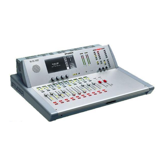
- Page 1 Studer OnAir 1000 Digital Broadcast Mixing Console, SW V4.0/4.03 Operating and Service Instructions...
- Page 2 Copyright by Studer Professional Audio GmbH Studer Professional Audio GmbH Printed in Switzerland Technical Documentation Order no. 10.27.4892 (Ed. 0704) Althardstrasse 30 CH-8105 Regensdorf – Switzerland http://www.studer.ch Subject to change Studer is a registered trade mark of Studer Professional Audio GmbH, Regensdorf...
-
Page 3: Safety Information
Safety Information Safety Information To reduce the risk of electric shock, do not remove covers. No user- serviceable parts inside. Refer servicing to qualified service personnel (i.e., persons having appropriate technical training and experience neces- sary to be aware of hazards to which they are exposed in performing a repair action, and of measures to minimize the danger of themselves). - Page 4 Installation/Maintenance/ESD General Installation Instructions Please consider besides these general instructions also any product-specific instructions in the “Installation” chapter of this manual. Unpacking Check the equipment for any transport damage. If the unit is mechanically damaged, if liquids have been spilled or if objects have fallen into the unit, it must not be connected to the AC power outlet, or it must be immediately disconnected by unplugging the power cable.
- Page 5 ESD/Repair Class I Equipment (Mains Operation) Should the equipment be delivered without a matching mains cable, the latter has to be prepared by a trained person using the attached female plug (IEC320/C13 or IEC320/C19) with respect to the applicable regulations in your country.
- Page 6 Installation/Maintenance/ESD tor) and that also takes into consideration the EMC requirements. When deciding between radial, surface, or combined grounding, the advan- tages and disadvantages should be carefully evaluated in each case. • Use shielded cables where shielding is specified. The connection of the shield to the corresponding connector terminal or housing should have a large surface and be corrosion-proof.
- Page 7 ESD/Repair material in which the replacement assembly was shipped. If this should not be the case, any claim for a possible refund will be null and void. • Unpacked ESD sensitive components should only be handled in ESD protected areas (EPA, e.g. area for field service, repair or service bench) and only be touched by persons who wear a wristlet that is connected to the ground potential of the repair or service bench by a series resistor.
- Page 8 Repair/Disposal SMD Components Studer has no commercially available SMD components in stock for serv- ice purposes. For repair, the corresponding devices have to be purchased locally. The specifications of special components can be found in the serv- ice manual. SMD components should only be replaced by skilled specialists using ap- propriate tools.
- Page 9 CE Declaration of Conformity Studer Professional Audio GmbH, CH-8105 Regensdorf, declare under our sole responsibility that the product Studer OnAir 1000, Digital Mixing Console, (starting with serial no. 1000) to which this declaration relates, according to following regulations of EU directives and amendments •...
- Page 10 Ambient Temperature Units and systems by Studer are generally designed for an ambient tem- perature range (i.e. temperature of the incoming air) of +5...+40 °C. When rack mounting the units, the intended air flow and herewith adequate cool- ing must be provided.
- Page 11 Appendix evaporation (sublimation) may be expected; otherwise the system must be heated and dried while switched off. A system without visible internal formation of ice or condensation should be heated up with its own heat dissipation, as homogeneously (and subse- quently as slow) as possible;...
- Page 12 Appendix Appendix 2: Mains Connector Strain Relief For anchoring connectors without a mechanical lock (e.g. IEC mains con- nectors), we recommend the following arrangement: Procedure: The cable clamp shipped with your unit is auto-adhesive. For mounting please follow the rules below: •...
- Page 13 The following Terms and Conditions grant the right to use all programs of Studer that are part of the System and/or its options at the time of its deliv- ery to the Customer, as well as the installation software on the original data disk and the accompanying documentation (“License Material”).
- Page 14 Reverse Engineering Reverse engineering is only permitted with the express consent of Studer. The consent of Studer can be obtained but is not limited to the case in which the interface-software can not be provided by Studer. In any case Studer has to be informed immediately upon complete or partial reverse engineering.
- Page 15 OnAir 1000 Digital Mixing Console NEW FEATURES WITH SW V4.02/V4.03 Momentary/Latching Key Functions PFL and Talkback Keys Latching: If a PFL key or one of the talkback keys (N–1 A, N–1 B, AUX 1, AUX 2, or STUDIO) is pressed for less than 0.2 s, the function is now latching, and the key is illuminated.
- Page 16 OnAir 1000 Digital Mixing Console PFL Signaling When a PFL key is activated, pin 11 of the STUDIO MON CTRL connec- tor is activated (i.e. pulled to ground). This pin was formerly labeled as “Spare OUT 2”. STUDIO MON CTRL (D-type, 25 pin, male): Signal Signal Signal...
- Page 17 OnAir 1000 Digital Mixing Console However, no Monitor Extension module can be installed in an OnAir 1000 console, which means that no other functions (as known from OnAir 2000M2 consoles) can be configured. Additional REC Signaling Output An additional REC signaling output has been provided on pin 9 of the SIGN.
- Page 18 OnAir 1000 Digital Mixing Console Additional Customer Codes Code 0x00000800: Used to disable dimming of the CR monitor speakers during talkback from the studio to the control room. Code 0x00001000: Used to disable dimming of the studio monitor speakers during talkback from the control room to the studio.
-
Page 19: Table Of Contents
OnAir 1000 Digital Mixing Console CONTENTS PART 1 – OPERATING INSTRUCTIONS Introduction..................................1-1 Block Diagram OnAir 1000, SW V4.0........................1-2 Definition of Terms ..............................1-4 General ....................................2-1 Utilization for the Purpose Intended ......................... 2-1 First Steps ................................. 2-1 2.2.1 Unpacking and Inspection..........................2-1 2.2.2 Installation ................................ - Page 20 OnAir 1000 Digital Mixing Console Master Functions................................5-1 Login/Logout................................5-1 AUX and Insert Control ............................5-2 N–1/Audition Bus and Telephone Hybrid Control....................5-3 5.3.1 N–1 and Audition Bus Routing ........................5-4 Studio Monitoring ..............................5-5 Mixer Setup................................5-6 Snapshots.................................. 5-7 5.6.1 Recall a Snapshot from Memory ........................
- Page 21 OnAir 1000 Digital Mixing Console Machine Control................................8-1 Keys and LEDs ................................. 8-1 Control Outputs ................................ 8-3 8.2.1 CTRL OUT1..............................8-3 8.2.2 CTRL OUT2..............................8-3 Control Inputs ................................8-4 8.3.1 CTRL IN................................8-4 8.3.2 EXT PFL Input ..............................8-4 CTRL OUT1/2 & CTRL IN Application Examples ....................8-5 Automation..................................9-1 Introduction ................................
- Page 22 OnAir 1000 Digital Mixing Console SW Update ................................12-1 12.1 Software Structure..............................12-1 12.1.1 CPU Software Package ..........................12-1 12.1.2 DSP Software Package ........................... 12-1 12.1.3 Important Information for Software Update to V4.0 ..................12-1 12.2 SW Update Procedure ............................12-2 12.2.1 Error Handling ...............................
- Page 23 OnAir 1000 Digital Mixing Console Dip Switches and Jumpers ............................15-1 15.1 Input Units ................................15-1 15.2 TB Mic Input Units..............................15-2 15.3 Telephone Hybrid Interface ............................ 15-3 15.4 Analog Output Units ............................... 15-4 15.5 Digital Output Units..............................15-5 15.6 Insert Unit ................................15-5 15.7 Clock Sync Interface...............................
- Page 24 OnAir 1000 Digital Mixing Console 0-6 Contents Part 1 SW V 4.0 Date printed: 23.10.03...
-
Page 25: Introduction
14.2. The OnAir 1000 can be integrated seamlessly with a broadcast automation system (CAB) like Studer’s DigiMedia. The OnAir 1000 is based on a touch-screen user interface. Only the most important functions have hardware control elements, making it very easy to use. -
Page 26: Block Diagram Onair 1000, Sw V4.0
OnAir 1000 Digital Mixing Console Block Diagram OnAir 1000, SW V4.0 INPUTS INPUT CHANNELS INPUT PCBs INPUT CHANNEL 1 CTRL I/O DC REJ FILTER/ PREAMP 1 CHANNEL Σ PROGRAM INSERT FADER BALANCE MUTE DJ MIC 1 DIG PAD EQU. PHASE Σ... - Page 27 OnAir 1000 Digital Mixing Console MAIN OUTPUTS MASTER AND MONITORING METER 1 METER 2 PPM / VU PPM / VU BARGRAPH BARGRAPH Σ PROGRAM D ( Σ ON AIR / D) SEND RETURN Σ PROGRAM A Σ PROGRAM Σ FADER PGM INSERT LIMITER INSERT...
-
Page 28: Definition Of Terms
OnAir 1000 Digital Mixing Console Definition of Terms Terms used in this manual: Inputs: The physical inputs of the input unit; all input units have mono or stereo inputs with A/B selection. Analog inputs are equipped with 3-pin XLR connectors. Digital inputs are equipped with AES/EBU inputs on XLR connectors, and S/PDIF inputs on Cinch/RCA and optical (TOSlink) connectors. -
Page 29: General
Check the condition of the equipment for signs of shipping damage. If there should be any complaints you should immediately notify the for- warding agent and your nearest Studer distributor. Please retain the original packing material because it offers the best pro- tection in case your equipment ever needs to be transported. -
Page 30: Adjustments, Repair
The primary fuse is located within the power supply unit and cannot be changed. In case of failure, the complete supply unit must be replaced. Please contact your nearest Studer representative. Fuse for DC Supply: For DC operation there is a second fuse located on the PSU Sub Board (please refer to chapter 14.1... -
Page 31: Technical Specifications
OnAir 1000 Digital Mixing Console Technical Specifications (subject to change without notice) General Level specs, digital, in dB dB, referenced to full modulation (dB , dB Full Scale) Level specs, analog, in dBu: 0 dBu 0.775 V Level specs, analog, in dBu Level in dBu for full modulation ( 0 dB Sampling rate: 48 kHz ±100 ppm (internally synchronized) - Page 32 OnAir 1000 Digital Mixing Console Analog Outputs Analog outputs are transformer-balanced with XLR connectors. Output level +4 to +24 dBu @ R = 100 kΩ; = 300 Ω +4 to +23 dBu @ R D/A converter 24 bit (Delta-Sigma, 128 × oversampling) Dynamics typ.
- Page 33 OnAir 1000 Digital Mixing Console Dimensions (in mm) General 2-5 Date printed: 23.10.03 SW V 4.0...
- Page 34 OnAir 1000 Digital Mixing Console 2-6 General SW V 4.0 Date printed: 23.10.03...
-
Page 35: Operating Concept
(e.g. equalizer parameters), or directly through the assigned touch-screen (e.g. EQ ON/OFF). This innovative user surface is called the “Touch’n’action” concept and is patented by Studer. In broadcast applications many DJs and operators without a special techni- cal education work on the same mixing console. Every DJ has his pre- ferred console settings, mainly EQ parameters for his microphone. -
Page 36: Touch-Screen Unit
OnAir 1000 Digital Mixing Console 3.1.2 Touch-Screen Unit START RESET STOP [1] Touch-Screen The touch-screen display is used for parameter entries; it normally displays the current time and date in digital and analog formats, as well as the fader and the user stopwatches. [2] Rotary Encoders Depending on the current status, the rotary encoders are used for parameter settings. -
Page 37: Metering Section
OnAir 1000 Digital Mixing Console 3.1.3 Metering Section The OnAir 1000 mixing console is equipped with two dual 30-LED stereo level meters and one correlator meter for each of the level meters. The meters can be set to simultaneously display either VU or PPM. Two –1 –1 LEDs below the respective scale indicate the selected mode (for mode set-... -
Page 38: Monitoring And Talkback Section
OnAir 1000 Digital Mixing Console 3.1.4 Monitoring and Talkback Section ON-AIR CR-MIC STUDIO-MIC AUX 2 AUX 1 EXT 3 AUDIT EXT 2 EXT 1 OFF AIR N–1 B N–1 A AUX 2 AUX 1 STUDIO PFL / TB PHONES TALK BACK [1] Control Room (CR) Monitoring Selector Ten mutually releasing keys for selecting the control room monitoring signal from the following sources:... - Page 39 OnAir 1000 Digital Mixing Console [3] PFL/TB PFL/TB: Volume control for the built-in PFL/TB speaker. EXT PFL: The EXT PFL input can be used as an external PFL input to the monitor- ing unit. If pressed, the key is illuminated, the external signal is routed to the PFL output, and the external PFL control output is active.
-
Page 40: Fader Section
OnAir 1000 Digital Mixing Console 3.1.5 Fader Section AUTO TAKE OVER [10] AUX1 AUX2 INS1 INS2 [1] Channel Label Display Four-character display, indicating the label of the input channel momen- tarily selected. The channel label can be set in the INPUT CONFIG. page; refer to chapter 11.2.1. - Page 41 OnAir 1000 Digital Mixing Console [7] SEL Multi-function key: • For activating the Channel Control page on the touch-screen for this respective input channel. For details please refer to chapters 4.4 and 4.5. • If the INPUT CONFIG. page is already displayed on the central touch- screen, pressing the SEL key in a fader strip selects the corresponding input channel for configuration.
-
Page 42: Connector Panels
OnAir 1000 Digital Mixing Console Connector Panels Analog-biased (left) and digitally-biased (right) versions 3-8 Operating Concept SW V 4.0 Date printed: 23.10.03... -
Page 43: Channel Functions
OnAir 1000 Digital Mixing Console CHANNEL FUNCTIONS The OnAir 1000 has ten input channel faders and two master faders on the surface. The input channel fader strips consist of a four-character channel label display, two input selector keys, a SEL key, an EQ key, an OVL overload indication, a PFL key, the fader, an ON and an OFF key. -
Page 44: Faders
OnAir 1000 Digital Mixing Console EQ Key: The EQ key opens the EQ/filter page on the touch-screen, and the corre- sponding SEL key is illuminated, indicating that parameters of this input channel are displayed. The EQ key is illuminated if the equalizer is on. By observing if the EQ keys are illuminated, it can be determined at a glance in which input channels the equalizer settings are active. - Page 45 OnAir 1000 Digital Mixing Console fader), “PF” (pre-fader), “ON” or “OFF”. These touch-screen fields are highlighted if selected. INS1 / INS2: The INS1 or the INS2 LED is on if the respective input channel's signal is INS1 routed trough one of the analog inserts 1 or 2. The inserts are controlled in INS2 the AUX MASTER/INSERTS page on the touch-screen.
-
Page 46: Channel Control Page, Microphone Input
OnAir 1000 Digital Mixing Console Channel Control Page, Microphone Input The Channel Control page for a microphone input channel is opened by pressing the SEL key of a mic channel's fader strip. PHANTOM Touching the “ON” part of the PHANTOM field turns the 48 V phantom power on;... -
Page 47: Channel Control Page, Line Input
OnAir 1000 Digital Mixing Console Channel Control Page, Line Input The Channel Control page for a line input channel is opened by pressing the SEL key of a digital or an analog line input channel's fader strip. MODE Line level inputs have a MODE field defining whether the input is proc- essed in “ST”(-ereo) or in “MONO”... - Page 48 OnAir 1000 Digital Mixing Console Access Permission: Depending on the access permission (see chapter 10) of the user currently logged in, the functions not available to this user will not be displayed on the Channel Control page; an example is given below. This user cannot ac- cess the following parameters: •...
-
Page 49: Eq/Filter Page, Microphone Input
OnAir 1000 Digital Mixing Console EQ/Filter Page, Microphone Input The EQ/filter page for a microphone input channel is opened by pressing the EQ key of a microphone input channel's fader strip. If the user has no access permission to the EQ and filter parameters, the EQ/filter page will not be displayed. -
Page 50: Eq/Filter Page, Analog Line/Digital Input
OnAir 1000 Digital Mixing Console EQ/Filter Page, Analog Line/Digital Input The EQ/filter page for a line input channel is opened by pressing the EQ key of an analog or digital line input channel's fader strip. If the user has no access permission to the EQ parameters, the EQ/filter page will not be displayed at all. -
Page 51: Master Functions
OnAir 1000 Digital Mixing Console MASTER FUNCTIONS Master functions are not input channel-related but global functions. These are audio functions (AUX master level, studio monitoring), non-audio functions (telephone hybrid control, clock, stopwatch), snapshot manage- ment, and system configuration. Touching one of the LOGIN, AUX & INSERT, TEL, STUDIO MON, MIXER SETUP, or HOME–CHN ON/OFF fields will always lead to the corresponding page. -
Page 52: Aux And Insert Control
OnAir 1000 Digital Mixing Console ministration table, his name is DEFAULT USER. The access permissions of this user can be edited. His record cannot, however, be deleted, and no password can be defined for him. AUX and Insert Control The AUX MASTER/INSERTS page is entered by touching the AUX & INSERT field on the touch-screen. -
Page 53: N-1/Audition Bus And Telephone Hybrid Control
OnAir 1000 Digital Mixing Console Each signal can be assigned to one insert only. If a signal is already as- signed to an insert, it will not appear in the channel/bus label field during signal selection for another insert. The insert is assigned per input unit and not per physical input, which means that the insert assignment is always valid for both physical inputs A and B of an input channel. -
Page 54: N-1 And Audition Bus Routing
OnAir 1000 Digital Mixing Console 5.3.1 N–1 and Audition Bus Routing For bus routing, first open the INPUT CONFIG. page of the desired input channel (the example above shows the INPUT CONFIG. page of a digital input channel; for a mic input channel, the INPUT CONNECTOR field is not displayed, and for an analog line input channel, there will be the LEVEL and HEADROOM fields displayed instead). -
Page 55: Studio Monitoring
OnAir 1000 Digital Mixing Console Studio Monitoring The STUDIO MONITORING SOURCE page is opened by touching the STUDIO MON field. This page allows selecting one of six signals to be routed to the studio monitoring loudspeakers and headphones. This selec- tion can also be done via a pushbutton remote control from the studio (op- tional accessory “Studio Talkback Box”... -
Page 56: Mixer Setup
OnAir 1000 Digital Mixing Console Mixer Setup The Mixer Setup page (SNAPSHOTS/MIC SET/CHAN ROUT) gives access to several function groups used for setting the general status of the console. These are: Global snapshots, private snapshots, global micro- phone (mic) settings, private microphone settings, global channel routings. At the left of the Mixer Setup page there is the SNAPSHOTS area. -
Page 57: Snapshots
OnAir 1000 Digital Mixing Console Snapshots A snapshot is a copy of a momentary console setup. It contains all pa- rameters (as input selection, input gain, phase, phantom power, balance or panorama setting, EQ settings, AUX settings, input channel ON/OFF, and insert assignment), except fader positions and PFL. -
Page 58: Save A Snapshot To Memory
OnAir 1000 Digital Mixing Console 5.6.2 Save a Snapshot to Memory Saving a snapshot is done by touching a snapshot field, followed by SAVE MEM. The keyboard page appears where the snapshot name can be en- tered or edited (max. 20 characters). If the existing name is to be kept, just touch the <--¦... -
Page 59: Mic Settings
OnAir 1000 Digital Mixing Console Mic Settings A mic (microphone) setting is a set of parameters (EQ, gain, phantom power) for a single microphone input channel. Thus, every DJ or an- nouncer can store his preferred mic settings and recall them at any time. Up to four private mic settings for each user (max. -
Page 60: Save A Mic Setting To Memory
OnAir 1000 Digital Mixing Console 5.7.2 Save a Mic Setting to Memory Creating a mic setting means saving a set of equalizer and gain parameters for a single microphone input channel under a given name into the con- sole's internal flash memory. This is done by first selecting the microphone input channel to be stored, then touching a MIC SET field, followed by SAVE MEM. -
Page 61: Routing
OnAir 1000 Digital Mixing Console Routing The OnAir 1000 features an input channel router that allows to route the output of any input unit (including the complete parameter set, as stereo mode, gain, filter, sends, bus assignment) to any fader strip. Please note that the two physical inputs A and B of the same input unit cannot be as- signed to different fader strips, as the input selector switch is located be- fore the preamplifier. - Page 62 OnAir 1000 Digital Mixing Console The program and record master fader assignment is fixed (PGM MASTER to fader no. 11, REC MASTER to fader no. 12). These two faders can be disabled (CLEAR) and re-enabled (SET), but not re-assigned to input channels.
- Page 63 OnAir 1000 Digital Mixing Console ROUTING page. In such a case, a dashed vertical line is displayed for the corresponding input unit (channels 01, P, and R in the picture above). Input Units not Connected to a Fader Strip There are cases where the signals must be routed “to the background”, i.e., it is possible for input channels to be active, but without operating ele- ments on the console surface, e.g.
-
Page 64: Recall A Channel Routing From Memory
OnAir 1000 Digital Mixing Console 5.8.2 Recall a Channel Routing from Memory Automatical Recall: Every logged-in user has his own user channel routing that is loaded either automatically when logging-in, or manually. This is defined by customer code 0x00000200 (see chapter 11.2.11). -
Page 65: Delete A Channel Routing From Memory (Administrator Only)
OnAir 1000 Digital Mixing Console 5.8.4 Delete a Channel Routing from Memory (Administrator Only) Previously stored channel routing data are overwritten when saving a channel routing, as described in chapter 5.8.3. For the administrator, it is also possible to delete a global channel routing without overwriting it by new data. -
Page 66: Using Pc-Cards
OnAir 1000 Digital Mixing Console Using PC-Cards Snapshots, mic settings, and global channel routings can be saved to a PC- Card or loaded from the card into the console's flash memory. Using PC- Cards, parameter settings of a console can also be copied to an other con- sole, provided that both have the same configuration. -
Page 67: Save A Snapshot/Mic Setting/Channel Routing To Pc-Card
OnAir 1000 Digital Mixing Console 5.9.2 Save a Snapshot/Mic Setting/Channel Routing to PC-Card To save a snapshot, a mic setting, or a channel routing to a PC-Card, first select a snapshot, a mic setting, or a channel routing in the Mixer Setup page. -
Page 68: Administrator
OnAir 1000 Digital Mixing Console 5.10 Administrator 5.10.1 Features • The administrator has access to all private and global snapshots, mic set- tings, and channel routings. • The administrator has no private snapshots or mic settings, but one user channel routing. The administrator's Mixer Setup page is shown above. -
Page 69: Admin Selection Of Snapshots/Mic Settings/Channel Routings
OnAir 1000 Digital Mixing Console 5.10.2 Admin Selection of Snapshots/Mic Settings/Channel Routings The system administrator can display and modify the private snapshot, mic setting, and channel routing data of any user. This feature has been implemented in order to enable the setting of pa- rameters in a private snapshot, mic setting, or channel routing to which the particular user has no access. -
Page 70: Users With And Without A Password
OnAir 1000 Digital Mixing Console 5.10.3 Users with and without a Password When a normal user enters the Mixer Setup page before logging-in (which means he is treated as the default user), he works with the default user's data. He can LOAD, RECALL, SAVE, or DELETE all of the default user's data in the console's memory or on the PC-Card. -
Page 71: User Administration
OnAir 1000 Digital Mixing Console 5.11 User Administration USER ADMINISTRATION is only accessible for the system administra- tor. Refer to chapter 10 for details on how to set up function access per- mission and new user accounts. 5.12 System Configuration System configuration is a separate function group that can be accessed only by the system administrator or by users having access permission. -
Page 72: Watch And Stopwatch
OnAir 1000 Digital Mixing Console 5.13 Watch and Stopwatch The watch and stopwatch functions are displayed on the right-hand side of the touch-screen (except when the keyboard or routing pages are active). The term “watch” refers to the time-of-day in analog and digital format, the day-of-week, and the date in an abbreviated format. -
Page 73: Fader Stopwatch
OnAir 1000 Digital Mixing Console 5.13.2 Fader Stopwatch The upper one of the two stopwatches is called the fader stopwatch. It always restarts at 00:00:00 when a new audio channel is activated (e.g. channel ON, fader open, and output bus selected). In other words, it dis- plays the elapsed time of the audio channel opened last. -
Page 74: Pgm And Rec Master Faders
OnAir 1000 Digital Mixing Console 5.14 PGM and REC Master Faders The console provides two master faders (PGM, fader no. 11, and REC, fader no. 12) located on the far right of the CHANNEL ROUTING page (“P” and “R”). Their assignment is fixed, they cannot be re-assigned to in- put channels. -
Page 75: Monitoring
OnAir 1000 Digital Mixing Console MONITORING Control Room Monitoring The CR monitoring source selector has 10 keys to select one out of six internal and four analog external sources. The key of the selected source is illuminated. Source Description General purpose output bus. AUX2 is illuminated Auxiliary 2 AUX 2 if selected. - Page 76 OnAir 1000 Digital Mixing Console If the monitoring source is AUDIT (audition bus), the monitor speakers are either dimmed (DIM key illuminated), muted (CUT key illuminated), or not affected at all, according to the configuration (see chapter 11.2.2 details). If talkback is active, the level of the monitor speakers is dimmed by 20 dB and the DIM key is illuminated.
-
Page 77: Studio Monitoring
OnAir 1000 Digital Mixing Console Studio Monitoring The built-in studio monitoring functions are based on a touch-screen menu on the control screen. The STUDIO MONITORING SOURCE page allows one of six sources to be selected for routing to the studio speakers and headphones. -
Page 78: Talkback
OnAir 1000 Digital Mixing Console Talkback There is a choice among five talkback destinations from any control room (CR) microphone. A key is assigned for each destination as can be seen in the table below. Function Description The connection between DJ mic and Clean-feed TB to Tele- B (N–1B, e.g. -
Page 79: Talkback Settings
OnAir 1000 Digital Mixing Console 6.3.1 Talkback Settings Signaling and talkback can be configured independently. The “SIGN.” setting in the INPUT CONFIG. page is used only for signaling (red light) and monitoring (cut and dim). The “TB SOURCE” parameter in the INPUT CONFIG. page sets the as- signment of the talkback source, i.e. -
Page 80: External Pfl
OnAir 1000 Digital Mixing Console For deactivating the internal TB microphone and activating the external TB mic inputs, the INPUT CONFIG. page for the channels 11 and 12 is used: External PFL The OnAir 1000 provides an external PFL audio input. If the EXT PFL key is pressed, the key is illuminated, and the signal at the EXT PFL input (EXTERNAL MONITOR INPUT A connector) is routed to the PFL bus. -
Page 81: Signaling
OnAir 1000 Digital Mixing Console SIGNALING For control room and studio, signaling is provided by means of open- collector outputs (9-pin D-type connector “SIGN.” on the rear of the con- sole; for connection details, refer to chapter 14.11). One output is available for each of the following statuses: •... - Page 82 OnAir 1000 Digital Mixing Console 7-2 Signaling SW V 4.0 Date printed: 23.10.03...
-
Page 83: Machine Control
OnAir 1000 Digital Mixing Console MACHINE CONTROL The OnAir 1000 provides different control inputs and outputs. These can be used e.g. for switching an input channel on and off, or for starting, stopping, and cueing of the connected source unit (as CD/cartridge/MD players, tape recorders, or a CAB system). - Page 84 OnAir 1000 Digital Mixing Console Key 3/LED 3 The functionality of the third key (labeled “OFF”) depends on the console configuration. It can act as channel OFF key or trigger a LOCATE func- tion. The key 3 functionality is set in the COMMON SETTINGS page: Console configuration (valid for all channels): Key 3 (“OFF”) function Key 2 (“ON”) function...
-
Page 85: Control Outputs
OnAir 1000 Digital Mixing Console Control Outputs 8.2.1 CTRL OUT1 This open-collector output is normally used to start external devices, such as CD players or a CAB system, to play the next track. On the INPUT CONFIG. page (see chapter 8.1), other functions can be assigned individu- ally for each audio input. -
Page 86: Control Inputs
OnAir 1000 Digital Mixing Console Control Inputs 8.3.1 CTRL IN A CTRL IN control input is available for each audio input channel. This input channel's function can be selected in the INPUT CONFIG. page (see chapter 8.1). Input configuration (for each channel individually): CTRL IN mode CTRL IN signal NOT ACTIVE... -
Page 87: Ctrl Out1/2 & Ctrl In Application Examples
CTRL OUT1 –> remote control Fader open/close, or channel ON/OFF, or — — FADER input “fader start” PFL ON/OFF Review function of Studer D730/D731: CTRL OUT2 –> Studer D730/ pre-listening with PFL and subsequent locate ON & FADER PREVIEW — D731, remote control input to the last cue address. - Page 88 OnAir 1000 Digital Mixing Console 8-6 Machine Control SW V 4.0 Date printed: 23.10.03...
-
Page 89: Automation
A serial interface (RS232/RS422) is used for communication with the CAB system. Studer DigiMedia: Information on how to connect and operate the OnAir 1000 mixing con- sole with a DigiMedia CAB system is given in the current DigiMedia op- erating instructions. -
Page 90: Application Handling
OnAir 1000 Digital Mixing Console Application Handling 9.3.1 Configuration for Automation Control Input channels must be assigned to the automation system in the console configuration in order to be controlled by an external CAB system. AUTOMATION CONFIG. is reached from the SYSTEM CONFIG. page: The AUTOMATION CONFIG. -
Page 91: Output Selection
OnAir 1000 Digital Mixing Console 9.3.3 Output Selection The CAB is able to control the output assignment (program/record bus) of the currently selected input of any input channel. This allows, for instance, to route speech to the program output, and music to the record output. 9.3.4 Start a New Title from Schedule In automation mode, the CAB can start a new title automatically (it is also... -
Page 92: Indication Of The Currently Playing Input Line
OnAir 1000 Digital Mixing Console 9.3.5 Indication of the Currently Playing Input Line As the OnAir 1000 is not equipped with motor faders, a clear indication of the channel currently “playing” is necessary. Under the following conditions the respective channel label is in continous scrolling mode, indicating “ON-AIR”... -
Page 93: User Modes
OnAir 1000 Digital Mixing Console USER MODES 10.1 Purpose of User Modes The console is used in different studios with different working practice and different personnel structure. A large part of users in broadcast studios is not technically oriented. A mixing console meeting their requirements must be simple to use, reliable and free of “unnecessary”... -
Page 94: Access To Configurable Functions Of The Console
OnAir 1000 Digital Mixing Console 10.2 Access to Configurable Functions of the Console Normal Adminis- Function Description Default User User trator Loglist management Accept an entry (delete entry from list) configurable configurable accessible View the log list accessible accessible accessible Aux Master Inserts on AUX page configurable... - Page 95 OnAir 1000 Digital Mixing Console Normal Adminis- Function Description Default User User trator EQ parameters: Switch EQ for this channel input on Switch EQ for this channel input off Set EQ high shelving corner freq. to low Set EQ high shelving corner freq. to high Switch high-pass filter off Switch high-pass filter on configurable...
-
Page 96: User Administration
OnAir 1000 Digital Mixing Console 10.3 User Administration The described access permission allows different functionality ranges to important console functions for each user. By assigning an appropriate ac- cess permission to each user, it is possible to fit the OnAir 1000 console to very different working environments. -
Page 97: Administration Functions
OnAir 1000 Digital Mixing Console 10.4 Administration Functions By the system administrator, a user record can be created (NEW), changed (EDIT), or deleted (DELETE). Create User Record: To create a new user record, touch NEW in the USER ADMINISTRA- TION page. The NEW USER page appears with empty input fields: The USER NAME and PASSWORD fields are filled in, using the key- board page. - Page 98 OnAir 1000 Digital Mixing Console sired name, and then reload the snapshots, mic settings, and channel rout- ing from the card. After touching SAVE, the old record is replaced by the new one. This procedure has to be performed this way in order to avoid name conflicts in the console's memory and on the PC-card.
-
Page 99: Log-In Procedure And Defaults
OnAir 1000 Digital Mixing Console Delete User Record: To delete a user record from the user administration table, a record must be selected by touching the desired name field. A dialog box appears; if deleting the user is confirmed there, the selected user is permanently re- moved from the memory, and the user record disappears from the USER ADMINISTRATION page. - Page 100 OnAir 1000 Digital Mixing Console the system does not check for a password in this case, this user’s private data are not protected, and any other user can access them. If a console is operated by one person only, the system administrator sim- ply has to enable all access rights for the default user.
-
Page 101: Configuration
OnAir 1000 Digital Mixing Console CONFIGURATION In order to meet the requirements for different studio environments, the OnAir 1000 is highly configurable. A configuration is “static”, which means that it cannot be changed during normal operation. Although snapshots rely on a certain configuration, the configuration data are not stored together with the snapshots. - Page 102 OnAir 1000 Digital Mixing Console Configuration Menu Tree Diagram: INPUT CHANNEL No./Input type INPUT A/B LABEL SIGN. TB SOURCE INPUT CONNECTOR (digital line input only) LEVEL (analog line input only) USER ADMIN. HEADROOM (analog line input only) CTRL. OUT 1 CTRL.
-
Page 103: Input
OnAir 1000 Digital Mixing Console 11.2.1 Input There are three slightly different INPUT CONFIG. pages for editing input configurations, depending on the type of input unit. The pages for micro- phone, analog line, and digital line input channels are shown below. Microphone Input Channel Analog Line Input Channel Digital Input Channel... - Page 104 OnAir 1000 Digital Mixing Console LABEL The LABEL field is used for giving a name to a channel. Touching this field, the keyboard page opens. The channel label display in the fader strip can display labels with up to four characters (upper case only). The whole name scrolls by in the display as long as the respective input selector key A or B is pressed, or after a new name has been saved.
- Page 105 OnAir 1000 Digital Mixing Console CTRL. OUT 1/2 Please refer to chapter 8 for details on this subject. CTRL. IN Please refer to chapter 8 for details on this subject. BUS ASSIGNMENT When touching the BUS ASSIGNMENT field, the display changes as fol- lows, allowing to select the N–1 and the audition bus assignments: The TO...
-
Page 106: Common Settings
OnAir 1000 Digital Mixing Console 11.2.2 Common Settings The COMMON SETTINGS page contains the following configuration possibilities: CR DIM WHEN AUDITION SEL When the Audition bus is selected as a CR monitoring source, and a CR mi- crophone input channel is ON, the CR monitor speaker level will be attenuated (DIM), muted (CUT), or nothing happens at all (DON'T CARE). -
Page 107: Output
OnAir 1000 Digital Mixing Console 11.2.3 Output On the OUTPUT CONFIG. page, the types of the output signals on the AUX 1, AUX 2, and AUDITION buses can be set. 11.2.4 Level Meter The LEVEL METER configuration page defines the signal sources for the level meters no. -
Page 108: Time And Date
OnAir 1000 Digital Mixing Console 11.2.5 Time and Date The watch gives a time, day-of-week, and date display. The standard time reference is an internal battery-buffered real-time clock (RTC). The RTC continues to run even when the console is switched off. Therefore it is un- necessary to set the watch at power-up. -
Page 109: System Test
OnAir 1000 Digital Mixing Console The watch configuration is done in the TIME & DATE FORMAT page. This page is displayed after touching the “FORMAT” field on either the TIME or the DATE page. Both time and date can be displayed in two formats (select with TIME FORMAT or DATE FORMAT, respectively), as shown below: Time Format Digital Time Indication... -
Page 110: Software Update
OnAir 1000 Digital Mixing Console 11.2.7 Software Update More information on this subject can be found in chapter 12.2. 11.2.8 Console Dump A “console dump” consists of configuration data (CONFIG. DATA), snap- shots (global and private), mic settings (global and private), and channel routings. -
Page 111: System Synchronization
OnAir 1000 Digital Mixing Console When loading data from the PC-Card, the console data will be overwritten. Therefore this procedure has to be confirmed in a dialog box. The EXIT field returns to the SYSTEM CONFIG. page. A Configuration is loaded into the console by selecting CONFIG. DATA, LOAD FROM PC-CARD, and EXECUTE. -
Page 112: Automation
OnAir 1000 Digital Mixing Console If the console is synchronized to an external signal, a message box is dis- played if synchronization is lost; a “Missing External Clock” warning is added to the error list. If the console was synchronized to either WORDCLOCK or AES/EBU and a “no sync”... -
Page 113: Customer Code
OnAir 1000 Digital Mixing Console 11.2.11 Customer Code There is a possibility to activate optional, customer-specific functions. For this purpose, a feature called Customer Code is used. Please note that the customer codes are displayed and entered in hexadecimal. Code 0x00000000 Default Setting Code 0x00000002 High Shelving Filter Modification... - Page 114 OnAir 1000 Digital Mixing Console Code 0x00000200 Automatic Channel Routing When activated, the user's own channel routing is automatically activated during log-in. Otherwise, the channel routing has to be manually loaded after having logged-in. Code 0x00000400 Higher Attenuation of Sum Signal During Talkback Allows to attenuate the “N”...
-
Page 115: Sw Update
Control Front Board I firmware must be installed, or the Control Front Board has to be replaced. Studer will not take any responsibility nor accept warranty claims for not following this procedure. Please make sure that the console data are backed-up prior to any modifi- cation as the internal data structure is different. -
Page 116: Sw Update Procedure
OnAir 1000 Digital Mixing Console 12.2 SW Update Procedure After touching the SW UPDATE field in the SYSTEM CONFIG. page, a dialog box appears, where the user can decide whether he wants to load the software (PC-CARD), or whether he wants to stop the software update procedure (CANCEL). - Page 117 OnAir 1000 Digital Mixing Console Then the new software is copied from the PC-Card into the console's Flash EPROM. This will take several minutes. Finally the last dialog box appears. The system can now be re-booted (REBOOT) with the new software, or, if required and available, an op- tional customer code (CCODE) can be entered.
-
Page 118: Error Handling
OnAir 1000 Digital Mixing Console 12.2.1 Error Handling If the software update is interrupted by any reason, the system has to be re- booted. Afterwards, a message box appears with the message that the sys- tem software must be updated. Should the PC-Card not contain valid code, the following dialog box ap- pears. -
Page 119: System Diagnostics And Error Handling
OnAir 1000 Digital Mixing Console SYSTEM DIAGNOSTICS AND ERROR HANDLING The OnAir 1000 error system concept consists of three topics: Diagnostics and Error Handling The system diagnostics software works completely in the background. The user takes notice of the diagnostics only in case of an irregularity. The system diagnostics consists of finding out the console’s hardware configu- ration and detecting discrepancies to the system configuration. -
Page 120: System Diagnostics
OnAir 1000 Digital Mixing Console As more than one system message can occur at the same time, the diag- nostics software manages a Log List containing one entry for each system message, completed by time and date of occurrence. If the Log List con- tains more than one entry, the PREV and NEXT fields appear on the touch-screen. - Page 121 OnAir 1000 Digital Mixing Console Diagnostics and Error Handling – System Configuration Detection Error ID Type Indication Diag. Box Error Text (Conflict) Information Module for Channels [n] - [m] installed! Information Module for Channels [n] - [m] added! Warning Module for Channels [n] - [m] removed! Information Central Module installed! Information...
- Page 122 OnAir 1000 Digital Mixing Console Diagnostics and Error Handling – Flash Checksum Tests Error ID Type Indication Diag. Box Error Text (Conflict) Warning Flash verification - All Snapshots, Mic Settings and Channel Routings lost due to software version mismatch! Warning Flash verification - Customer Configuration corrupted! Warning Flash Verification - Console Configuration corrupted!
- Page 123 OnAir 1000 Digital Mixing Console Snapshot Controller (cont.) Information Mic Setting not recalled due to corrupted Mic Setting Data! Information Snapshot not loaded because user [%s] (owner of the Snapshot) is not defined on this mixing console! Information Mic Setting not loaded because user [%s] (owner of the Mic Setting) is not defined on this mixing console! Information All Private Mic Settings used.- Only [n] of [m] Private Mic...
-
Page 124: Indication On Failure Of Restricted Functions
OnAir 1000 Digital Mixing Console 13.2 Indication on Failure of Restricted Functions Usually, there is no indication of any error or warning if the execution of functions is prohibited in case of restrictions, because the user immediately notices whether the desired function is performed correctly. Nevertheless, some warnings need to be indicated to the user as a feedback, e.g. -
Page 125: System Test
OnAir 1000 Digital Mixing Console 13.3 System Test The system test can be activated by touching the SYSTEM TEST field on the SYSTEM CONFIG. page. The SYSTEM TEST selection page appears on the touch-screen: 13.3.1 Buttons/Faders Test Selecting the BUTTONS/FADERS test brings the console into a mode where the controls of the console can be checked. -
Page 126: Display Test
OnAir 1000 Digital Mixing Console Fader Calibration: Touching the CAL FADER field brings up the CAL FADER page which allows checking and calibrating the faders: For each fader, a bargraph indicates the current fader position. There are two calibration possibilities: The 0 dB point, and the fader start trigger point. -
Page 127: Pc-Card Test
OnAir 1000 Digital Mixing Console 13.3.3 PC-Card Test Two types of PC-Cards are used with the console: • Program card, used for software upgrade • Data card, used for storing and recalling console configuration, snap- shot data, and mic settings When having touched PC-CARD, the inserted PC-Card is checked for battery voltage and write protection. - Page 128 OnAir 1000 Digital Mixing Console 13-10 Diagnostics SW V 4.0 Date printed: 23.10.03...
-
Page 129: Wiring And Hardware Information
OnAir 1000 Digital Mixing Console WIRING AND HARDWARE INFORMATION 14.1 DC Supply The power supply is made of a primary switching power supply unit, de- livering a 24 V voltage to the secondary Power Supply that converts this voltage to the required ±15 V, +5 V, and +24 V. On the Primary Supply Unit (89.20.2013) the mains voltage selection is performed automatically. - Page 130 OnAir 1000 Digital Mixing Console Alarm Output Power alarm is triggered if the internal or external supply voltage drops below 23.0 V; then the POWER ALARM LED on the front panel is illu- minated, and a power alarm signal is output on pin 4 of the DC supply connector.
-
Page 131: Redundant Power Supply
OnAir 1000 Digital Mixing Console 14.2 Redundant Power Supply Redundant Supply Versions: There exist four basic versions of the OnAir 1000 Digital Mixing Console: Analog- and digitally-biased versions both are available with standard mains and/or 24 V supply, as well as with dual, redundant 24 V supply together with a separate, external 19”... - Page 132 OnAir 1000 Digital Mixing Console ferent phases of the mains), two mains switches, two primary power sup- plies, two separate DC cables to the console, and two separate secondary DC-DC converters within the console. The primary AC/DC converters are contained in an external 19” rack mount case.
- Page 133 OnAir 1000 Digital Mixing Console output on pin4 of both DC supply connectors of the console, illuminating the ”POWER ALARM” LED on the front panel of the Redundancy PSU. The power alarm output is a relay contact (max. 40 V/200 mA). Its be- haviour depends on jumper J1 on the PSU sub board.
-
Page 134: Mic Input
OnAir 1000 Digital Mixing Console 14.3 Mic Input Each microphone input unit features two inputs and A/B switchover. In- puts A and B are transformer-balanced mono microphone inputs. The maximum input level is such that also mono line level signals can be proc- essed if required. - Page 135 OnAir 1000 Digital Mixing Console For CTRL OUT 2A/B, seven operating modes are available: NOT ACTIVE Output is always open. LOCATE KEY Output is closed (i.e. pulled to GND) if the OFF key is pressed and the input channel is active. PREVIEW Output is closed if the PFL key is active and the PREVIEW function has been activated;...
-
Page 136: Analog Line Input
OnAir 1000 Digital Mixing Console 14.4 Analog Line Input Each analog line input unit has an input selector for two stereo input sources (A and B). Both inputs A and B are electronically balanced and are equivalent. Pin Assignments: LINE inputs A/B (XLR, 3pin, female): Signal Chassis Input +... -
Page 137: Tb Mic Input
OnAir 1000 Digital Mixing Console 14.6 TB Mic Input The TB Mic input units are used for connecting internal and/or external talkback microphones. In the standard configuration, the OnAir 1000 fea- tures an internal electret talkback microphone internally connected to the “CR”... -
Page 138: Telephone Hybrid Interface
OnAir 1000 Digital Mixing Console internal 1 kΩ current limiting resistor. The “+5 V OUT” output can supply up to 50 mA. The sum of all “+5 V” outputs for all input CTRL connectors of the whole console must not exceed 300 mA. External TB Mic: The TB Mic input units are equipped with a balanced mic input (XLR, 3pin, female) for the connection of external microphones. -
Page 139: Analog Output
OnAir 1000 Digital Mixing Console 14.8 Analog Output The analog output units provide a transformer-balanced, dual stereo or mono output signal (selectable with a jumper). Output signal selection is performed on the PCB by means of jumpers; refer to chapter 15.4. -
Page 140: Analog Insert
OnAir 1000 Digital Mixing Console 14.10 Analog Insert There are two analog, electronically balanced stereo insert sends and re- turns (1 and 2) that can be assigned to any of the input channels, or to the program or the record bus. Selection of the input channel to be assigned to the insert is performed on the AUX MASTER/INSERT page by means of the fourth rotary encoder. -
Page 141: Monitoring
OnAir 1000 Digital Mixing Console 14.11 Monitoring The monitoring section is a (mainly analog) monitoring unit. It has five external analog inputs in addition to the console’s internal buses. It pro- vides analog output signals for headphones and loudspeakers in the control room as well as in the studio. - Page 142 OnAir 1000 Digital Mixing Console STUDIO MONITOR (AUDIO) A (volume control, 9pin D-type, female): Signal Speakers volume pot, wiper (note 1) n.c. Phones volume pot, wiper (note 1) +5 V (note 2) Chassis Chassis +5 V (note 2) Note 1: 10 kΩ...
- Page 143 OnAir 1000 Digital Mixing Console STUDIO MON CTRL (D-type, 25 pin, male): Signal Signal Signal +5 V SUPPLY Lamp EXTERN Switch TB TO TEL2 COMMON Lamp Spare2 Lamp PGM Switch AUX1 n.c. Lamp AUX2 Switch OFF AIR Lamp PFL Switch EXTERN +5 V SUPPLY Lamp Spare1 Switch TB TO TEL1...
- Page 144 OnAir 1000 Digital Mixing Console EXT PFL CTRL (D-type, 9 pin, male): Signal Signal +5 V SUPPLY External PFL IN + External PFL IN – External TB to CR – External PFL OUT Spare OUT External TB COMMON + External TB to Studio – 1 k Ω...
- Page 145 OnAir 1000 Digital Mixing Console SIGN. (D-type, 9 pin, male): Signal Signal +5 V SUPPLY COMMON ON AIR IN – Spare IN – or Ext. CR DIM IN – * CR MIC OUT STUDIO MIC OUT PGM OUT Spare OUT * depending on Customer Code setting 1 k Ω...
- Page 146 OnAir 1000 Digital Mixing Console CTRL (D-type, 9 pin, male): This connector provides all the signals required for a guest headphone. The “Phones OUT” signal is the same as the one on the GUEST jack socket on the same PCB. Signal Signal Phones OUT left...
-
Page 147: Serial Interface
OnAir 1000 Digital Mixing Console 14.12 Serial Interface The serial interface provides a serial communication link according to either RS232 or RS422 specification (switch-selectable). It is used for the connection to and communication with a computer-assisted broadcasting system (CAB); for details on CAB systems refer to chapter Pin Assignments: RS422 (D-type, 9 pin, male):... -
Page 148: Time Sync Interface
OnAir 1000 Digital Mixing Console 14.14 Time Sync Interface With the time sync interface, the console’s internal clock can be synchro- nized to an external time reference signal, such as a DCF77 or GPS re- ceiver, or a Mobatime clock providing a serial output signal. The current software supports AFNOR and Seiko protocols, as well as SMPTE bi- phase timecode (Leitch). - Page 149 OnAir 1000 Digital Mixing Console Wiring and Hardware 14-21 Date printed: 23.10.03 SW V 4.0...
- Page 150 OnAir 1000 Digital Mixing Console 14-22 Wiring and Hardware SW V 4.0 Date printed: 23.10.03...
-
Page 151: Dip Switches And Jumpers
OnAir 1000 Digital Mixing Console DIP SWITCHES AND JUMPERS The DIP switch and jumper positions are printed on the PCBs, except for the TB Mic input unit and the Analog Output unit; for these two assem- blies, drawings have been included in the following chapters for compo- nent location. -
Page 152: Tb Mic Input Units
OnAir 1000 Digital Mixing Console 15.2 TB Mic Input Units Input Unit Position: On the Talkback Mic input units, the position is set with a jumper: Unit Position: Jumper Position: 11 (TB Mic Input CR) IN 5 12 (TB Mic Input Studio) IN 6 TB OUT UNBAL... -
Page 153: Telephone Hybrid Interface
OnAir 1000 Digital Mixing Console Jumper Setting (cont.): EXT. TB CTRL ON/OFF Activates or deactivates the external TB control input on P4 or P8. Factory setting: EXT. TB CTRL ON. IN1...8 Address selection. Factory setting for position 11, TB Mic Input “CR” (i.e., the built-in electret TB mic): IN5;... -
Page 154: Analog Output Units
OnAir 1000 Digital Mixing Console 15.4 Analog Output Units The Analog Output units have jumpers for mono/stereo selection and for selecting the desired output signal, individually for each of the outputs A and B. The output level is set with trimmer potentiometers, separate by outputs A/B and by left/right channels. -
Page 155: Digital Output Units
OnAir 1000 Digital Mixing Console 15.5 Digital Output Units The Digital Output units have two DIP switches (marked A and B on the PCB) for selection of the desired output signal for each of the two inde- pendent outputs. Selection is done according to the following table: Output Signal and DIP Switch no.: Unit Position... -
Page 156: Time Sync Interface
OnAir 1000 Digital Mixing Console 15.8 Time Sync Interface DIP Switch The external time reference signal for the Time Sync interface is selected with a DIP switch. The DIP switch setting is displayed in hexadecimal on the TIME & DATE FORMAT page (TIME SYNC. PROTOCOL field) for easy verification. -
Page 157: Monitoring Controller Pcb
OnAir 1000 Digital Mixing Console Time Sync Interface 15.9 Monitoring Controller PCB On the Monitoring Controller PCB, all DIP switches must be set to their OFF position. 15.10 Level Meter PCB For information on jumper setting and level meter calibration, please refer to the OnAir 1000 Service Manual. -
Page 158: Dsp Pcb
OnAir 1000 Digital Mixing Console 15.12 DSP PCB Jumper Setting: On the DSP PCB, only the “CFG1” jumper must be inserted. Do not change this setting. 15.13 Control Front Board I DIP Switches: On the Control Front Board I, all DIP switches must be set to their OFF position. -
Page 159: Index
OnAir 1000 Digital Mixing Console INDEX Central Screen Test..........13-7 Change User Record ........... 10-5 A, B............... 3-7 Channel ..............1-4 A/B Input Keys ............. 4-1 Channel Control page ......4-1, 4-4, 4-5 Access Permission ..........4-5 Channel Functions ..........4-1 Access Rights............ - Page 160 OnAir 1000 Digital Mixing Console CTRL OUT1 ............8-3 EXT 3 ..........3-4, 5-5, 6-1, 6-3 CTRL OUT1/2 & CTRL IN Appl. Examples ..8-5 EXT PFL ...............3-5 CTRL OUT2 ............8-3 EXT PFL CTRL........6-6, 14-16 CTRL. IN ............11-5 EXT PFL input............6-6 CTRL. OUT 1/2 ..........11-5 EXT PFL Input............8-4 customer code........
- Page 161 OnAir 1000 Digital Mixing Console INPUT CONNECTOR ........11-4 mains voltages............2-1 Input PCB ............. 1-4 MASTER FADER ASSIGNMENT....11-6 input unit position..........15-1 Master Faders............4-2 input unit-to-fader strip assignment....5-13 Master Functions ..........5-1 input router.............3-1, 4-1 Meinberg............. 15-6 INS1 ..............
- Page 162 OnAir 1000 Digital Mixing Console OVL...............3-6 Rotary Encoders Test ..........13-7 OVL (Overload) ............4-2 routing ..........3-1, 5-6, 5-11 RS232........9-1, 14-19, 14-20, 15-6 RS422........9-1, 14-19, 14-20, 15-6 RS485..............15-6 packing ..............2-1 RTC ............5-23, 11-8 PAN...............4-4 parallel studio interface.........6-4 password........... 5-21, 10-1, 10-5 PC-Card.............
- Page 163 OnAir 1000 Digital Mixing Console talkback........... 3-2, 3-4, 3-5, 6-4 user access rights ..........10-1 talkback destinations..........3-5 User Administration........5-22, 10-4 talkback listening ...........3-5, 6-4 USER ADMINISTRATION page ...... 10-4 Talkback Mic Input unit position ....... 15-2 User Channel Routing......... 5-16 Talkback Settings..........
- Page 164 OnAir 1000 Digital Mixing Console 16-6 Index SW V 4.0 Date printed: 23.10.03...
- Page 165 OnAir 1000 Digital Mixing Console CONTENTS PART 2 – SERVICE INSTRUCTIONS Features ...................................1-1 System Architecture..............................1-1 Signal Processing..............................1-2 Audio Buses................................1-3 Host Controller .................................1-3 Hardware ..................................2-1 Input Units ................................2-2 Output Units ................................2-3 Monitoring................................2-3 Touch Screen................................2-5 User Surface ................................2-5 Signal Processing and System Control ........................2-5 Standard Power Supply Versions ..........................2-6 Redundant (Dual) Power Supply Versions .......................2-8 Level Meters................................2-11...
- Page 166 OnAir 1000 Digital Mixing Console 0-2 Contents Part 2 SW V4.0 Date printed: 24.10.03...
-
Page 167: Features
OnAir 1000 Digital Mixing Console FEATURES • Fully digital mixing console • Touch-screen based user interface (“Touch’n’action”) • 10 input + 2 master channels • Integrated input router (for input unit-to-fader strip assignment) • Flexible configuration • Snapshots • PC-Cards for snapshots, configuration, and software update •... -
Page 168: Signal Processing
OnAir 1000 Digital Mixing Console Signal Processing 1-2 Features SW V4.0 Date printed: 24.10.03... -
Page 169: Audio Buses
OnAir 1000 Digital Mixing Console Signal processing is based on 24-bit DSPs (Texas Instruments TMS57070). The input channels are processed by six DSP chips (i.e. two stereo channels per DSP). The summing bus is a PLD (programmable logic device) design and can handle up to 32 bit. The resulting sums are further processed by three additional DSPs. - Page 170 OnAir 1000 Digital Mixing Console 1-4 Features SW V4.0 Date printed: 24.10.03...
-
Page 171: Hardware
OnAir 1000 Digital Mixing Console HARDWARE Hardware 2-1 Date printed: 24.10.03 SW V4.0... -
Page 172: Input Units
OnAir 1000 Digital Mixing Console Input Units The two basic versions of the Studer OnAir 1000 console are equipped with the following input units: Channel No. Digitally-biased version: Analog-biased version: Mic Input Unit 1.942.720.xx Mic Input Unit 1.942.720.xx Mic Input Unit 1.942.720.xx Mic Input Unit 1.942.720.xx... -
Page 173: Output Units
OnAir 1000 Digital Mixing Console Output Units All Studer OnAir 1000 consoles are equipped with the following output units: 2 × Digital Output Units 1.942.624.xx, and 3 × Dual Analog Output Units 1.942.621.xx (transformer-balanced). For details on output units, please refer to the OnAir 1000 Operating Man- ual, chapters 14.8 and... - Page 174 OnAir 1000 Digital Mixing Console MAIN OUTPUTS MASTER AND MONITORING METER 1 METER 2 PPM / VU PPM / VU BARGRAPH BARGRAPH Σ PROGRAM D ( Σ ON AIR / D) SEND RETURN Σ PROGRAM A Σ PROGRAM Σ FADER PGM INSERT LIMITER INSERT...
-
Page 175: Touch Screen
OnAir 1000 Digital Mixing Console Touch Screen The LC display has a resolution of 640 × 200 pixels. A cold-cathode fluo- rescent lamp (CFL) provides the back light, having a typical lifetime (50% brightness) of 10'000 to 15'000 hours (meaning about 13 to 20 months of continuous operation). -
Page 176: Standard Power Supply Versions
OnAir 1000 Digital Mixing Console Standard Power Supply Versions The power supply is made of a primary switching power supply unit, de- livering a 24 V voltage to the secondary Power Supply that converts this voltage to the required ±15 V, +5 V, and +24 V. On the Primary Supply unit (89.20.2013) the mains voltage selection is performed automatically. - Page 177 OnAir 1000 Digital Mixing Console Alarm Output Power alarm is triggered if the internal or external supply voltage drops below 23.0 V; then the POWER ALARM LED on the front panel is illuminated, and a power alarm signal is output on pin 4 of the DC supply connector.
-
Page 178: Redundant (Dual) Power Supply Versions
OnAir 1000 Digital Mixing Console Redundant (Dual) Power Supply Versions There exist four basic versions of the OnAir 1000 Digital Mixing Console: Analog- and digitally-biased versions both are available with standard mains and/or 24 V supply, as well as with dual, redundant 24 V supply together with a separate, external 19”... - Page 179 OnAir 1000 Digital Mixing Console different phases of the mains), two mains switches, two primary power supplies, two separate DC cables to the console, and two separate secondary DC-DC converters within the console. The primary AC/DC converters are contained in an external 19” rack mount case.
- Page 180 OnAir 1000 Digital Mixing Console output on pin4 of both DC supply connectors of the console, illuminating the ”POWER ALARM” LED on the front panel of the Redundancy PSU. The power alarm output is a relay contact (max. 40 V/200 mA). Its behaviour depends on jumper J1 on the PSU sub board (see component layout diagram in the circuit diagrams chapter).
-
Page 181: Level Meters
OnAir 1000 Digital Mixing Console Level Meters Since the audio signals delivered from the DSP Board have an internal, so- called “left-justified” format, an interface is required for connecting the meters. This interface is integrated on the Level Meter Board (1.942.613.xx) and provides conversion to analog format for two stereo channels. - Page 182 OnAir 1000 Digital Mixing Console 2-12 Hardware SW V4.0 Date printed: 24.10.03...
-
Page 183: Configuration
OnAir 1000 Digital Mixing Console CONFIGURATION Software Configuration The software configuration defines the functionality of the console. SW configuration is described in chapter 11 of the OnAir 1000 Operating Manual. 3.1.1 N–1 Configuration Unlike in analog mixing consoles (where the N–1 signal is derived from the output sum by subtracting a channel signal), the N–1 are separate buses in the OnAir 1000. -
Page 184: Hardware Configuration
OnAir 1000 Digital Mixing Console Hardware Configuration The hardware needs correct addressing to allow communication between the software and the installed PCBs. At power-on the software checks if the hardware configuration has changed since the last power-off. In case of a failure (or a configuration mismatch), an information message is dis- played to inform the user on the failure (or changes). -
Page 185: Output Unit Configuration
OnAir 1000 Digital Mixing Console 3.2.2 Output Unit Configuration Digital Output Units The Digital Output Units (on positions 13 and 14) have two independent digital outputs conforming to the AES3-1992 standard. Each of these has two parallel output drivers. Since the digital output units are software- controlled, two DIP switches (marked A and B on the PCB) are used for selection of the desired output signal. -
Page 186: Dsp Board
OnAir 1000 Digital Mixing Console Analog Output Units The Analog Output Units (on positions 15...17) have a row of jumper pins for mono/stereo selection and for selecting the desired output signal, indi- vidually for each of the outputs A and B. Due to the high component count on the PCB, it was impossible to label the jumper pins;... -
Page 187: Service
1 kHz/–9 dB sine-wave bursts [10 ms on, 1.7 s off]). If neither a digital audio signal generator nor a test CD should be avail- able, contact Studer Product Support (www.studer.ch). • Analog audio level meter with balanced input (e.g. AudioPrecision System One, System Two, or Portable One;... -
Page 188: Removing And Inserting Assemblies
OnAir 1000 Digital Mixing Console Removing and Inserting Assemblies Assembly Location: Time Sync Interface Clock Sync Interface Telephone Hybrid Interface Serial Interface 1.942.650.xx 1.942.635.xx 1.942.640.xx 1.942.645.xx 4.2.1 Input and Output Assemblies Removal: • Open the console, as described in chapter 4.1. -
Page 189: Interface Assemblies
OnAir 1000 Digital Mixing Console • Installation of a PCB is performed in reverse order of its removal: Insert the PCB into the console, fasten it with the corresponding screws, connect the daisy-chain cable, and lock the multipin connectors. • After having re-installed the front cover with all the connections, perform a function check of your console. -
Page 190: Alignment
OnAir 1000 Digital Mixing Console Alignment 4.3.1 Power Supply 1.942.605.xx The +5 V (digital) is the only voltage that can be aligned. Procedure: Measure the +5 V supply between pins 1 and 3 of P19 on the DSP board. 10 9 8 7 6 5 4 3 2 1 5 4 3 2 1 4 3 2 1 Set the measured voltage to exactly +5.2 V with RA1 on the Power Supply... -
Page 191: Analog Outputs
OnAir 1000 Digital Mixing Console 4.3.2 Analog Outputs 1.942.621.xx Initial Setup: Perform the fader 0 dB point alignment for all faders, according to chapter 13.3.1 of the OnAir 1000 Operating Manual. Touch the MIXER SETUP field on the touch-screen, followed by SYSTEM CONFIG and INPUT. - Page 192 OnAir 1000 Digital Mixing Console • AUX master setting: - Select the AUX MASTER/INSERT page by touching the AUX & INSERT field. Activate the ON touch-screen fields for both AUX 1 and AUX 2 masters. Set the AUX 1 and AUX 2 gain to 0 dB. This position is marked with a dash.
- Page 193 OnAir 1000 Digital Mixing Console • Repeat this procedure for each of the four output connectors of each of the three Analog Output Units. Notes: Please consider that maximum undistorted level of the analog outputs is ) into a 300 Ω load. When setting the output levels, do +23 dBu (@ 0 dB not exceed a value of +14 dBu (with an input signal of –9 dB ), consid-...
- Page 194 OnAir 1000 Digital Mixing Console PCB Locations 15...17: Analog Output Units: Temporary jumper setting to PGM and RECORD – see jumper positions marked in black: OUTPUT LEVEL A RIGHT OUTPUT LEVEL A LEFT OUTPUT LEVEL OUTPUT LEVEL B RIGHT B LEFT B STEREO B MONO Notes:...
-
Page 195: Level Meter
OnAir 1000 Digital Mixing Console 4.3.3 Level Meter 1.942.613.xx Prerequisite: The console is set to a nominal level of +6 dBu and to 9 dB headroom (adjustment in the INPUT CONFIG. page of the analog line inputs). Notes: Changeover between VU, PPM, and PPM fast operation is done directly on the Level Meter PCB;... - Page 196 OnAir 1000 Digital Mixing Console (cont.) It is recommended to set all four jumpers to the same position – having different meter characteristics in one single console doesn’t make sense. J102, J103, J302, J303: Logarithmic/linear selection log: for PPM and PPM fast lin: for VU only.
- Page 197 OnAir 1000 Digital Mixing Console Align for a reading of –1.00 ±0.02 V , using the test points and trimmer potentiometers according to the table below. Meter no.: Test point: Align with: Meter 1 left TP102 RA101 Meter 1 right TP202 RA201 Meter 2 left...
- Page 198 OnAir 1000 Digital Mixing Console Check the voltages at the following test points: TP101/201/301/401: 285 mV TP102/202/302/402: –370 ±20 mV TP103/203/303/403: +2.55 ±0.10 V Feed a 400 Hz, –5.5 dB sine-wave signal to the console. Check: All LEDs of the bargraph must be illuminated. Check the voltages at the following test points: TP103/203/303/403: +3.8 V ±0.1 V...
-
Page 199: Tb Mic Input
OnAir 1000 Digital Mixing Console 4.3.4 TB Mic Input 1.942.719.xx TB OUT UNBAL AGND AGND EXT INT INT ELEC- TRET MIC AGND AGND EXT MIC EXT TB AGND CTRL TB OUT BAL IN B AGND IN A INSIG_N OUT B INSIG_P OUT A EXT_VCC... -
Page 200: Insert
OnAir 1000 Digital Mixing Console Alignment: MIC GAIN Depending on the output level of the microphone used, the limiter thresh- old is aligned with the MIC GAIN trimmer potentiometer (RA1). For the internal standard electret TB mic (nominal output level –60 dBu), the MIC INT/EXT jumper is set to the INT position, the GAIN jumper is set to the LO position. -
Page 201: Service Terminal
OnAir 1000 Digital Mixing Console SERVICE TERMINAL A service terminal connector is provided for servicing the OnAir 1000. The Service Terminal Task enables the user to bypass the “normal” user interface and approach the system in a more direct way. This is used in two specific cases: Service and Maintenance (normal user mode) -
Page 202: Connecting Cable
OnAir 1000 Digital Mixing Console Connecting Cable The terminal is connected to the 10-pin header connector (P13) labeled “SERVICE TERMINAL” on the Controller Board. The connecting cable is a straight 10-pin header to 9-pin D-type cable, where wire no. 10 is not used at the D-type connector side;... -
Page 203: Sw Update Via The Service Terminal
OnAir 1000 Digital Mixing Console The following terminal settings must be used: SW Update via the Service Terminal Procedure Dump all snapshots, mic settings, and configuration data to a PC-Card or to the service terminal. Connect the cable between the PC (COM1 or COM2) and the OnAir 1000 (“service terminal”... -
Page 204: Service Terminal Commands And Examples
OnAir 1000 Digital Mixing Console Service Terminal Commands and Examples Below, a series of Service Terminal commands is listed; for each com- mand, a possible reaction of the console is given as well. Most commands are self-explaining. However, please be aware of the fact that for using some of the commands, additional knowledge and skills are required. - Page 205 OnAir 1000 Digital Mixing Console ServIf:\debug\disp>? display Console Configuration Header display Current Console State Header display Global Console Configuration display Surface Configuration SI(:module-no>) display System Identification UC(:userID) display User Configuration display Channel Configuration IC(:input-no>) display Input Configuration display Channel Common Parameters CIP(:input-no>) display Channel Input Parameters...
- Page 206 OnAir 1000 Digital Mixing Console ServIf:\debug\tsend>? AUTOB to send Telegrams to Automation IOMB to send Telegrams to Input/Output Module CMBUS to send Telegrams to Control Module ServIf:\debug\tpoll>? IOMB to set polling rate on Input/Output Module Bus CMBUS to set polling rate on Control Module Bus ServIf:\debug\mdeb>? Msg-Debug iomb is...
- Page 207 OnAir 1000 Digital Mixing Console ServIf:\debug\disp>dp DIAGNOSTICS PARAMETERS : ======================== Main PLL State unlocked Video PLL State undefined Queue Statistics: Queue Name Buffer Max. Buffer Queue Name Buffer Max. Buffer full message free full message free iomb 93.1 cmbu 100.0 diag 100.0 chan...
- Page 208 OnAir 1000 Digital Mixing Console ServIf:\debug\disp>cch CONSOLE CONFIGURATION HEADER : ============================== SW-Version V4.0 23.01.2002 Number of Channels Checksum 0x294b ServIf:\debug\disp>csh CURRENT CONSOLE STATE HEADER : ============================== Block in Use In Use Checksum 0x2971 ServIf:\debug\disp>gcc GLOBAL CONSOLE CONFIGURATION : ============================== PFL Bus Source PF (PFL) PFL Cut when Chn active CR DIM when Audition...
- Page 209 OnAir 1000 Digital Mixing Console ServIf:\debug\disp\uc:userID>1 USER CONFIGURATION : userID ===================== User Name DEFAULT USER User Password Accept Error allowed Insert allowed Aux Send allowed Audition Level allowed N-1 Level allowed Aux 1 (chn) allowed Aux 2 (chn) allowed Phase allowed Phantom allowed Stereo allowed Gain/Cal allowed...
- Page 210 OnAir 1000 Digital Mixing Console ServIf:\debug\disp>cc CHANNEL CONFIGURATION : ======================= Number Array of Input Identification Auto Input Type of Inputs Ctrl mic inp mic inp mic inp mic inp mic inp mic inp ana line inp ana line inp ana line inp ana line inp ana line inp ana line inp...
- Page 211 OnAir 1000 Digital Mixing Console ServIf:\debug\disp>ccp CHANNEL COMMON PARAMETERS : =========================== Main Main FadLev on/off on/off Next -12800 -12800 inact inact -12800 -12800 inact inact -12800 -12800 inact inact -12800 -12800 inact inact -12800 -12800 inact inact -12800 -12800 inact inact -12800 -12800...
- Page 212 OnAir 1000 Digital Mixing Console ServIf:\debug\disp>mp MONITORING PARAMETERS : ======================= Studio Monitoring Source program Control Room Monitoring Source program Control Room Volume -4403 CR DIM CR CUT ST DIM ST CUT PFL/TB Volume -4613 Headphone Source cr stereo DJ Headphone Volume -3526 PFL to Monitor TB CR to Studio...
- Page 213 OnAir 1000 Digital Mixing Console ServIf:\debug\disp>iap INSERT ASSIGN PARAMETERS : ========================== Insert 1 assign Insert 1 on/off Insert 2 assign Insert 2 on/off Insert 3 assign Insert 3 on/off Insert 4 assign Insert 4 on/off ServIf:\debug\disp>crp CHANNEL ROUTING PARAMETERS : ========================== Channel to Fader Assignment assigned...
- Page 214 OnAir 1000 Digital Mixing Console ServIf:\debug\disp>scp SNAPSHOT CONTROL PARAMETERS : ============================= SnapShot Section active Section 0 SnapShot Section Write Pointer 0x00181F21 Array of 5 Global SnapShots : GRUNDEINST. Array of 10 pointers to Global Mic Settings : Array of 5 Global Channel Routings : For each user an array of 4 Private SnapShots : Private SnapShots of user DEFAULT USER: Private SnapShots of user with index 2:...
- Page 215 OnAir 1000 Digital Mixing Console ServIf:\debug\disp>cuc CUSTOMER CODE : =============== previous version 0x00000000 current version 0x00000000 ServIf:\debug\disp>user USER PARAMETERS : ================= Currently logged in user (name) ADMIN Currently logged in user (ID) ServIf:\debug\disp>tip TIMER PARAMETERS : ================== User Stopwatch State stopped Fader Stopwatch State stopped...
- Page 216 OnAir 1000 Digital Mixing Console 5-16 Service Terminal SW V4.0 Date printed: 24.10.03...
-
Page 217: Spare Parts, Accessories
OnAir 1000 Digital Mixing Console SPARE PARTS, ACCESSORIES [18] [11] [12] [14] [13] [10] [17] [15] [16] [19] Spare Parts: Item Order No.: Designation 1.942.500.08 Side panel, lower, left 1.942.500.06 Side panel, upper, left 1.942.500.09 Side panel, lower, right 1.942.500.07 Side panel, upper, right 1.942.500.02 Rear panel, for analog-biased version... - Page 218 OnAir 1000 Digital Mixing Console Accessory Set: 1.942.596.00 (shipped with the unit): • consisting of: Mains cable socket IEC320 • DC supply connector • Mains cable strain relief • Fader knobs: 2 each - red, orange, yellow, green, blue 6-2 Spare Parts SW V4.0 Date printed: 24.10.03...
- Page 219 OnAir 1000 Digital Mixing Console CONTENTS PART 3 – DIAGRAMS Software Survey (Which software component is located on which assembly? – please turn page) Assembly Survey (In the same order as given in the table of contents below) System Wiring Diagram, Standard Versions System Wiring Diagram, Redundant Supply Versions Supply Assembly No.
- Page 220 OnAir 1000 Digital Mixing Console Software Survey Assembly Software Label Position Controller 1.942.600.xx 1.942.904.xx IC30 1.942.905.xx IC31 1.942.926.xx IC18 1.942.951.28 IC28 IC28 1.942.951.28 IC26 IC26 SW Set, earlier version: 1.942.900.28 1.942.951.28 IC24 IC24 1.942.951.28 IC23 IC23 1.942.900.xx IC28 IC28 1.942.900.xx IC26 IC26 SW Set, from V3.08 and up: 1.942.900.xx 1.942.900.xx IC24...
- Page 221 OnAir 1000 Digital Mixing Console Assembly Survey [21] [17] [11] [11] [11] [10] [10] [10] [11] [11] [12] [12] [13] [13] [14] [15] [15] [16] [16] [16] [18] [19] [20] [12] [12] [12] [25] [22] [23] [24] Index Designation Order No. Index Designation Order No.
Need help?
Do you have a question about the SW V4.0 OnAir 1000 and is the answer not in the manual?
Questions and answers