Table of Contents

Related Manuals for Studer OnAir 2500


Summary of Contents for Studer OnAir 2500
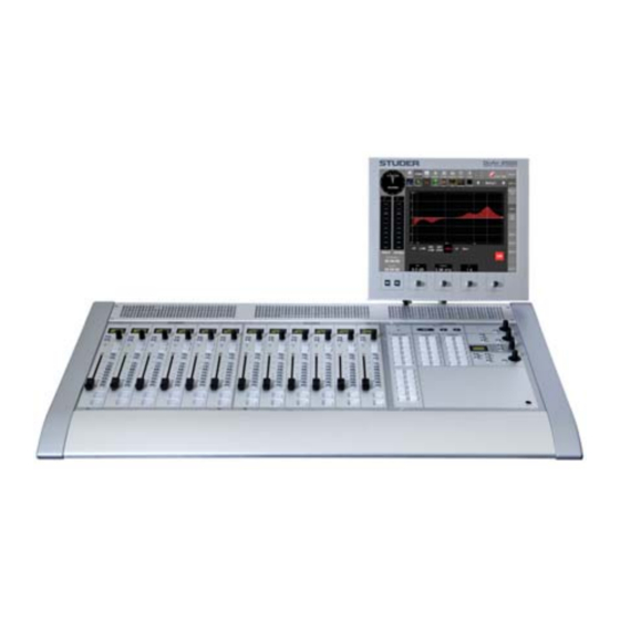
- Page 1 Studer OnAir 2500 Digital Mixing Console SW Version 3.0...
- Page 2 Copyright by Studer Professional Audio GmbH Studer Professional Audio GmbH Printed in Switzerland Technical Documentation Order no. 10.27.5190 (0708) Althardstrasse 30 CH-8105 Regensdorf – Switzerland http://www.studer.ch Subject to change Studer is a registered trade mark of Studer Professional Audio GmbH, Regensdorf...
-
Page 3: Safety Information
Safety Information Safety Information CAUTION To reduce the risk of electric shock, do not remove covers. No user-ser- RISK OF ELECTRIC SHOCK viceable parts inside. Refer servicing to qualified service personnel (i.e., DO NOT OPEN ATTENTION persons having appropriate technical training and experience necessary RISQUE DE CHOC ELECTRIQUE NE PAS OUVRIR to be aware of hazards to which they are exposed in performing a repair... - Page 4 Installation General Installation Instructions Please consider besides these general instructions also any product-specific instructions in the “Installation” chapter of this manual. Unpacking Check the equipment for any transport damage. If the unit is mechanically damaged, if liquids have been spilled or if objects have fallen into the unit, it must not be connected to the AC power outlet, or it must be immediately disconnected by unplugging the power cable.
- Page 5 Installation / EMC Class I Equipment (Mains Operation) Should the equipment be delivered without a matching mains cable, the latter has to be prepared by a trained person using the attached female plug (IEC 320 / C13 or IEC 320 / C19) with respect to the applicable regulations in your country.
- Page 6 EMC / Maintenance • Use a system grounding concept that satisfies the safety requirements (class I equipment must be connected with a protective ground conduc- tor) and that also takes into consideration the EMC require ments. When deciding between radial, surface, or combined grounding, the advantages and disadvantages should be carefully evaluated in each case.
- Page 7 ESD / Repair Electrostatic Discharge during Maintenance and Repair Caution: Observe the precautions for handling devices sensitive to electrostatic dis- charge! Many semiconductor components are sensitive to electrostatic discharge (ESD). The lifespan of assemblies contain ing such components can be dras- tically reduced by improper handling during maintenance and repair.
- Page 8 Repair / Disposal SMD Components Studer has no commercially available SMD components in stock for ser- vice purposes. For repair, the corresponding devices have to be purchased locally. The specifications of special components can be found in the service manual.
- Page 9 Studer Professional Audio GmbH, CH-8105 Regensdorf, declare under our sole responsibility that the product Studer OnAir 2500, Digital Broadcast Mixing Console (starting with serial no. 1001), to which this declaration relates, according to following regulations of EU directives and amendments •...
- Page 10 Beyond these specifications, possible problems are described below. Ambient Temperature Units and systems by Studer are generally designed for an ambient tempera- ture range (i.e. temperature of the incoming air) of +5 °C to +40 °C. When rack mounting the units, the intended air flow and herewith adequate cooling must be provided.
- Page 11 Appendix evaporation (sublimation) may be expected; otherwise the system must be heated and dried while switched off. A system without visible internal formation of ice or condensation should be heated up with its own heat dissipation, as homogeneously (and subsequently as slow) as possible;...
- Page 12 Appendix Appendix 2: Mains Connector Strain Relief For anchoring connectors without a mechanical lock (e.g. IEC mains connec- tors), we recommend the following arrangement: The cable clamp shipped with your unit is auto-adhesive. For mounting please Procedure: follow the rules below: •...
- Page 13 The following Terms and Conditions grant the right to use all programs of License Programs of Studer Studer that are part of the System and/or its options at the time of its delivery to the Customer, as well as the installation software on the original data disk and the accompanying documentation (“License Material”).
- Page 14 Reverse engineering is only permitted with the express consent of Studer. Reverse Engineering The consent of Studer can be obtained but is not limited to the case in which the interface software can not be provided by Studer. In any case Studer has to be informed immediately upon complete or partial reverse engineering.
- Page 15 OnAir 2500 Digital Mixing Console WIRING – IMPORTANT The OnAir 2500 ST MON and LAN wiring must comply with the following requirements: Cable Type: Cat 5e, with shielded connectors on both ends. Cable Dimensions: Max. Length for Min. Minimum Monitoring/TB Module...
- Page 16 OnAir 2500 Digital Mixing Console Important SW V3.0 Date printed: 18.07.08...
-
Page 17: Table Of Contents
OnAir 2500 Digital Mixing Console CONTENTS Introduction..................................1-1 Momentary/Latching Key Activation ........................1-2 Definitions, Acronyms, Abbreviations........................1-3 OnAir 2500 Audio Block Diagram ........................... 1-4 Application Example ..............................1-5 General..................................... 2-1 Utilization for the Purpose Intended ......................... 2-1 First Steps ................................. 2-1 2.2.1... - Page 18 OnAir 2500 Digital Mixing Console 5.3.6 Routing Pages ..............................5-25 5.3.6.1 (Routing) Input Page ..............................5-25 5.3.6.2 (Routing) Output Page ..............................5-27 5.3.6.3 (Routing) Insert Page ..............................5-28 5.3.6.4 (Routing) Mic Group Page............................5-29 5.3.6.5 (Routing) XL Assign Page ............................5-30 5.3.6.6...
- Page 19 OnAir 2500 Digital Mixing Console 5.10 User Access and Management ..........................5-72 5.10.1 Purpose................................5-72 5.10.2 General ................................5-72 5.10.3 Users................................. 5-72 5.10.4 Privileges................................5-73 5.10.5 Policies ................................5-73 5.10.6 Department Snapshots............................5-73 5.10.7 Parameter Tables .............................. 5-74 5.10.8 Internal Access Handling ..........................5-78 5.10.8.1 User GUI ..................................
- Page 20 OnAir 2500 Digital Mixing Console Config..................................6-12 6.5.1 Logical Inputs ..............................6-12 6.5.2 Logical Outputs..............................6-15 6.5.3 Fixed Outputs ..............................6-16 6.5.4 Fixed Out Meter ............................... 6-16 6.5.5 Insert Sends ..............................6-17 6.5.6 Insert Returns ..............................6-18 6.5.7 Encoder Sends..............................6-19 6.5.8...
- Page 21 OnAir 2500 Digital Mixing Console 6.5.30 User (User Management) ..........................6-73 6.5.30.1 Admin..................................6-73 6.5.30.2 Default..................................6-73 6.5.30.3 Users.................................... 6-74 6.5.30.4 Policies, Departments..............................6-76 6.5.31 License Manager .............................. 6-78 6.5.31.1 Information.................................. 6-78 6.5.31.2 Options ..................................6-78 6.5.32 Desk ................................. 6.5.32.1 Fader Assign 1 - Group 1 ............................6-79 6.5.32.2 Rotary Assign 2 - Group 2............................
- Page 22 OnAir 2500 Digital Mixing Console 0-6 Contents SW V3.0 Date printed: 23.07.08...
-
Page 23: Introduction
Mix-Minus (N–1/N–X) buses • Configurable key functions in case customization is needed • Easy networking and integration thanks to I/O sharing and CMS (Studer Call Management System) support • Complete integration with Radio Automation Systems; Monitora protocol via serial interface or tunnelled via TCP/IP •... -
Page 24: Momentary/Latching Key Activation
Momentary/Latching Key Activation ¹ A lot of key presses during console operation are repetitive in order to com- pare settings or to make quick checks for monitoring purposes. Studer has reduced the amount of needed key presses tremendously by incorporating a special logic for these cases. -
Page 25: Definitions, Acronyms, Abbreviations
OnAir 2500 Digital Mixing Console Definitions, Acronyms, Abbreviations Description After-fader (as opposed to PF, “pre-fader”) Balance (for stereo input sources) If the “broadcast PFL mode” (also referred to as “PFL cut on channel active” function) is Broadcast PFL enabled, audio signals are cut from the PFL bus if the channel is ON and the fader is open. -
Page 26: Onair 2500 Audio Block Diagram
OnAir 2500 Digital Mixing Console OnAir 2500 Audio Block Diagram V3.0 INPUTS INPUT CHANNELS INS SEND GR METER CH METER CHANNEL OUT N–X De-S PHASE 9/10 CH INP CHANNEL DE-ESSER DYNAMICS FADER BALANCE STEREO 4-band ON/OFF 11/12 13/14 REC PF... - Page 27 OnAir 2500 Digital Mixing Console Σ MASTER / SEND AND MONITORING OUTPUTS Master AUX Listen N–X DIR OUT PP DIR OUT AP INS SEND CHANNEL OUT L (M) PGM MASTER R (M) FADER 9/10 11/12 L (M) REC MASTER 13/14...
-
Page 28: Application Example
OnAir 2500 Digital Mixing Console Application Example analog (Audio) digital (Audio) audio ADAT External I/O MADI TCP/IP (D21m Frame) network GPIO other formats Merger Card not supported Net Protocol control RS 422 Studio 8 x Line Out Guest 8 x Line In... -
Page 29: General
OnAir 2500 Digital Mixing Console GENERAL Utilization for the Purpose Intended The OnAir 2500 mixing console is intended for professional use. It is presumed that the unit is operated only by trained personnel. Servicing is reserved to skilled technicians. The electrical connections may be connected only to the voltages and signals designated in this manual. -
Page 30: 2.2.3 Adjustments, Repair, Cleaning
OnAir 2500 Digital Mixing Console Closed Passive, 2 Vents Active, 1 Fan, 1 Vent D21m D21m D21m Rear Front Rear Front Rear Front Operating Mode Total Height Max. Power Dissipation Closed 40 W Passive, w. Vents 80 W Active, w. Fan and Vent 200 W Card No. -
Page 31: 2.2.4 Usb Memory Device
OnAir 2500 Digital Mixing Console 2.2.4 USB Memory Device The OnAir 2500’s central screen is equipped with a USB slot. This allows to save console snapshots to a USB memory device or load them from the memory device to the console memory, which offers a convenient possibility for backup purposes or for copying parameter settings from one console to one or several others. - Page 32 OnAir 2500, 24 faders tbd kg Note: Depending on the application, the OnAir 2500 can have different config- urations. For this reason the values mentioned above are applicable only to a typical configuration; in an individual case, the values may differ.
-
Page 33: Operating Elements
OnAir 2500 Digital Mixing Console OPERATING ELEMENTS The Studer OnAir 2500 is based on the “Touch’n’Action” concept adopted from the OnAir 3000 and its predecessor, the OnAir 2000. Normal operation of the console has been kept as simple as possible, since it will mainly be operated by technically inexperienced users. - Page 34 OnAir 2500 Digital Mixing Console The console must be earthed, due to the mains input filter network being connected to the mains earth. If the earthing connection can be interrupted, for example, by unplugging the mains plug of an external power supply unit,...
-
Page 35: Connectors, Pin Assignments
OnAir 2500 Digital Mixing Console Connectors, Pin Assignments MIC IN / LINE IN (XLR 3f) LINE OUT 1-8 / CR LSP L/R (XLR 3m) Signal (Input) Signal (Output) Screen Screen In + Out + In – Out – LINE OUT 9-16... - Page 36 OnAir 2500 Digital Mixing Console AES / EBU IN / OUT (25-pin D-type, female) Signal (1-8) Signal (9-16) Signal (1-8) Signal (9-16) CH 7/8 out + CH 15/16 out + CH 7/8 out – CH 15/16 out – CH 7/8 out scrn...
-
Page 37: System Power
/50...60 Hz) with power factor correction. The mains switch is located at the rear, next to the power inlet. The OnAir 2500 is EN and UL approved. Redundancy The console can be equipped with a second, external 1U power supply unit for redundancy., supplying 24 V... - Page 38 OnAir 2500 Digital Mixing Console Please note that this key may also be configured as CUE key. The purpose of CUE is to feed the after-fader, after-pan and pre-ON audio signal of the desired channel or AUX send, group, or master (program, record) to the PFL bus. If active, the key is illuminated in yellow.
- Page 39 OnAir 2500 Digital Mixing Console Auto Take-Over Indication: The physical value and the internal processed value of the fader may be different. This can be the case after routing, snapshot, or CAB changes – or simply because a fader value has been changed with the GUI rotary encoder.
-
Page 40: Central Section
OnAir 2500 Digital Mixing Console Central Section The larger keys in this module have transparent snap-on caps for convenient labeling. 4.5.1 Rotary Assign Keys Each of the twelve upper keys of the 24 keys in this block is dedicated to... -
Page 41: Monitoring/Talkback Controls
OnAir 2500 Digital Mixing Console 4.5.2 Monitoring / Talkback Controls The monitoring and TB controls are used for the the DJ headphone and the built-in PFL/TB speaker, direct access to the monitoring sources and exter- nal sources, for talkback to destinations different from the N–X buses and for definable talkback groups. -
Page 42: Optional External Units
GPO signal. GPIO Boxes Two types of general-purpose desktop boxes in the OnAir 2500 design, both with an illuminated key, and one of them with three additional LEDs are available for many different applications, e.g. cough key, control of external devices, etc. - Page 43 OnAir 2500 Digital Mixing Console XLR Break-Out Box This box is implemented as a configurable, modular system. The empty box (1.949.580) can be equipped with different options for the left and right part. The picture above shows a break-out box equipped with two options no. 3 for microphone inputs (2 ×...
- Page 44 OnAir 2500 Digital Mixing Console Four of the 16 GPO signals (GPO 1...4, marked in black on the front panel) are connected to solid-state relays whose power terminals are wired to the Com- bicon terminals. These power contacts can switch AC loads from 24...240 V with a maximum total current of 5 A over all 4 relays.
-
Page 45: Operation
In addition to these hardware and GUI elements on the desk, the OnAir 2500 can also be operated by a PC or laptop computer running Windows 2000 or XP, where the OnAir 2500 user GUI is emulated. -
Page 46: Direct Access Keys
OnAir 2500 Digital Mixing Console Notes The ñ/Shift and Caps Lock functions of screen and USB keyboards are independent. In addition, the external keyboard usually supports more char- acters than the one on the central screen. These two facts are of particular importance when entering user passwords: Make sure that the upper/lower case setting of the USB keyboard is correct. -
Page 47: Central Screen
The CR and ST 2 (control room and studio) indicators work in parallel with the red light indicators on the monitoring/talkback module. An on-air condition is indicated by changing the color of the “Frisbee” symbol next to the OnAir 2500 label from blue to red. Operation 5-3 Date printed: 18.07.08... -
Page 48: Color Code
The three indicator fields (CAB, CMS, Router) show the current status of the optional interfaces to the CAB (computer assisted broadcast) system such as a Studer DigiMedia playout system, to the Call Management System, and to an external router control system. Each of them indicates three different statuses: Grayed out –... -
Page 49: Channel Pages
OnAir 2500 Digital Mixing Console 5.3.3 Channel Pages There are two ways to open the channel page and to automatically select the corresponding channel: Touching the Chan field in the main menu or press- ing one of the direct access keys in the channel strip. The channel page pops up and displays the selected channel functions. - Page 50 OnAir 2500 Digital Mixing Console Phase Inverts the audio signal for mono inputs; inverts the left channel signal for stereo inputs, except in the RR case (see below) – then of course it makes sense to invert the right channel signal. The Phase button is highlighted whenever phase inversion is active.
- Page 51 OnAir 2500 Digital Mixing Console Functions for Mono Inputs Mono inputs have the same functionality as the stereo inputs, but without a stereo mode selector, as shown above. Functions for Microphone Inputs +48 V Enables/disables the phantom power for the corresponding mic input; the button is highlighted when enabled.
- Page 52 OnAir 2500 Digital Mixing Console blue bar graph and in the Gain field; it is adjusted with the rotary encoder below the field. Notes: There is no relation between the gain setting and the configured headroom, as the headroom setting is only used for the level meters to indicate 0 dB at nominal level.
- Page 53 OnAir 2500 Digital Mixing Console On the other systems within the network, the Mic Control Access button turns to red and displays information on the system currently having access: If access is requested from another system, a user warning appears there: After confirmation with “Yes”, access is taken over by the other system where...
- Page 54 OnAir 2500 Digital Mixing Console Test Generator Functions For test purposes, the OnAir 2500 features an internal test signal generator available for every channel. While the generator is active, the normal chan- nel buttons in the left part of the page are disabled and displayed in gray. The test generator may only be activated by users having the appropriate access rights configured by the system administrator.
-
Page 55: Channel) De-Esser Page
OnAir 2500 Digital Mixing Console 5.3.3.2 (Channel) De-Esser Page Each channel has an integrated de-esser. This is a dynamically controlled filter, normally used to reduce the “s” components of a microphone signal. The filter range is placed over the signal’s “s” frequency components; if an “s”... -
Page 56: Channel) Equalizer Page
OnAir 2500 Digital Mixing Console 5.3.3.3 (Channel) Equalizer Page Each channel has a parametric four-band equalizer. If the user has no access permission to the EQ parameters, the EQ page is not displayed. Graph The red graph represents the EQ’s current frequency response curve, cumu- lated from all filters. -
Page 57: Channel) Dynamics Page
OnAir 2500 Digital Mixing Console 5.3.3.4 (Channel) Dynamics Page Each channel has an internal dynamics processor consisting of a limiter, a compressor, an expander, and a gate section. The dB readings automati- cally consider the selected amount of headroom (i.e., 0 dB indication = 0 dB –... -
Page 58: Channel) Aux Page
OnAir 2500 Digital Mixing Console Threshold The expander/gate threshold is displayed in dB and can be adjusted in a 96 dB range with the rotary encoder below the field. (Gate only): Please note that the gate has a fixed 6 dB hysteresis. This means that the gate is closed as soon as the level is equal to or below the adjusted threshold value;... -
Page 59: Channel) N-X Page
OnAir 2500 Digital Mixing Console 5.3.3.6 (Channel) N–X Page N–X Mode This is an indication on which main output assignment the channel’s contribu- tion to the N–X bus depends (PRG A or REC), or whether the bus is used as AUX bus (AF or PF); in the latter case, its control elements are displayed in orange as usual for an AUX bus. -
Page 60: Channel) Fdr/Bus Page
OnAir 2500 Digital Mixing Console 5.3.3.7 (Channel) FDR/Bus Page Joker Indicates the function currently configured to the “Joker” key on the channel strip. For configuration refer to chapter 6.5.1. Enables/disables pre-fader listening for the current channel (corresponds to the PFL key on the fader strip and works in parallel). PFL feeds the pre-fader audio signal of the current channel to the PFL bus. - Page 61 OnAir 2500 Digital Mixing Console PAN or Balance Depending on the current channel format, this is a panorama (mono), or balance (stereo) function. The PAN or Balance value is indicated by the yellow-colored bar graph. The exact value is displayed as a numerical value followed by L or R and can be set with the rotary encoder below the field in a range from 30L (fully left) over 0 (center) to 30R (fully right).
-
Page 62: Sum Pages
OnAir 2500 Digital Mixing Console 5.3.4 Sum Pages When touching Sum, the last used Master, AUX or N–X page opens for parameter adjustment. 5.3.4.1 (Sum) Master Page This page opens when selecting it from the Sum page. It allows parameter adjustments for the two main master buses PRG A and Record. -
Page 63: Sum) Aux Page
OnAir 2500 Digital Mixing Console 5.3.4.2 (Sum) AUX Page This page allows parameter adjustments for the two AUX master buses. Mono / Stereo The audio format (mono or stereo) of each AUX master bus can be set to mono or stereo when touching these buttons; the current selection is highlighted. -
Page 64: (Sum) N-X Pages
OnAir 2500 Digital Mixing Console 5.3.4.3 (Sum) N–X Pages The control elements for the eight N–X master buses are distributed on two pages with identical layout. Mono / Stereo The audio format of all N–X buses can be set to mono or stereo when touching these buttons;... -
Page 65: Monitoring Pages
OnAir 2500 Digital Mixing Console 5.3.5 Monitoring Pages Like all hardware elements, the console’s monitoring and talkback controls are available in the GUI as well and work completely in parallel. This has several advantages: A function can be controlled from a remote PC, e.g. for service purposes, or the user can control the parameters in the studio from his desk in the control room. -
Page 66: Monitoring) Cr Lsp (Loudspeakers) Page
OnAir 2500 Digital Mixing Console 5.3.5.2 (Monitoring) CR LSP (Loudspeakers) Page Cut / Dim These buttons allow muting/dimming the speakers; highlighted if active. The amount of Dim attenuation can be configured (see chapter 6.5.22.1). (Loudspeaker) Volume The volume of the monitoring system is indicated with the bar graph. The exact value is displayed in dB and set with the adjacent rotary encoder. -
Page 67: Monitoring) Cr Cue Page
OnAir 2500 Digital Mixing Console SP SRC “Split mode” - an additional, third signal may be monitored on the DJ phones. This is selected with the SP SRC rotary encoder and its display. SP SRC/MON When activating the SP SRC/MON button, this third signal is fed to the left channel;... -
Page 68: Monitoring) Studio 2 Page
OnAir 2500 Digital Mixing Console 5.3.5.5 (Monitoring) Studio 2 Page The controls of the studio 2 page are operated in parallel to the controls on the monitoring/talkback box in the studio. Source Selector The source selector buttons can be configured with the desired sources; the currently selected source is highlighted. -
Page 69: Monitoring) Tb Sp Page
OnAir 2500 Digital Mixing Console 5.3.5.6 (Monitoring) TB SP Page This page contains a part of the functionality found on the monitoring/TB module and works in parallel with its controls. For details refer to chapter 5.5.3. Talkback Destination Selector Buttons to select a talkback destination (or a group of destinations). For details refer to chapter 5.5.3. -
Page 70: Routing Pages
OnAir 2500 Digital Mixing Console 5.3.6 Routing Pages 5.3.6.1 (Routing) Input Page The input routing page allows setting up the mixing console’s input router; the general rule is that each input can be routed to any channel, but to exactly one channel only. -
Page 71: Routing) Output Page
OnAir 2500 Digital Mixing Console Lock, Unlock A connection may be protected from changes by selecting it and touching the Lock button. If locked, the Connect and Clear buttons are blanked, and a padlock symbol is indicated next to the input label. -
Page 72: Routing) Insert Page
OnAir 2500 Digital Mixing Console Connect When touching Connect, the connection is set at the crosspoint of the cursor lines. The blue bullet at the crosspoint indicates the selected type: Input DIR Out PP (pre-processing) DIR Out AP (after processing) -
Page 73: Routing) Mic Group Page
OnAir 2500 Digital Mixing Console PP / AP For input channels, the insert point can be set to either before (PP) or after (AP) the signal processing (EQ/compressor for groups, limiter for masters). 5.3.6.4 (Routing) Mic Group Page For ease of control, microphones may be grouped in Mic Groups. All mi- crophones within the same group may be switched on/off with one single, external Mic key (via a GP input). -
Page 74: Routing) Xl Assign Page
OnAir 2500 Digital Mixing Console 5.3.6.5 (Routing) XL Assign Page Extended Line (XL) Module: The XL box allows direct communication to up to twelve outside sources but may be used for different applications as well. This page allows assigning the desired sources to the box keys. -
Page 75: Routing) Bus Assign Page
OnAir 2500 Digital Mixing Console 5.3.6.6 (Routing) Bus Assign Page The bus assign page gives a kind of “reverse contribution” overview and allows routing channels to buses in a matrix style, as opposed to the con- ventional assignment from within the strip channels. It also gives the user a convenient view of the inputs currently assigned to a bus;... -
Page 76: Snapshot Pages
OnAir 2500 Digital Mixing Console 5.3.7 Snapshot Pages On this page the static (snapshot) automation is handled. For a general descrip- tion of the snapshot handling refer to chapter 5.7. 5.3.7.1 (SNAP) Shot Page Local Snapshot List The snapshot list in the left part of the page shows all snapshots available for the current user. -
Page 77: Snap) Route Page ("Partial Output Routing")
OnAir 2500 Digital Mixing Console naming the selected entry with the keyboard appearing then. When finished, confirm with Enter. Delete The Delete button is displayed only if an entry has been selected in the Local snapshot list, and if deleting is available for this entry. It allows deleting the selected entry after confirmation. -
Page 78: Snap) Ext Page
OnAir 2500 Digital Mixing Console 5.3.7.3 (SNAP) EXT Page Local Snapshot List The snapshot list in the left part of the page shows the local snapshots saved in the console’s memory. Only one entry can be selected at a time. Selection is done with the Local Snapshot rotary encoder. -
Page 79: Admin (System Administrator) Pages
OnAir 2500 Digital Mixing Console 5.3.8 Admin (System Administrator) Pages If the user has access rights to the console configuration, the Admin button is displayed. After touching it, the Display, Fader Cal, Firmware, Date/ Time, Config, Scrn Cal, and Setup buttons select the respective pages for basic settings and firmware version display. -
Page 80: Admin) Fader Cal Page
OnAir 2500 Digital Mixing Console 5.3.8.2 (Admin) Fader Cal Page First, select one of the fader modules to be calibrated by touching the cor- responding button. The screen then changes as follows: 0 dB Position Always required; please note that it is recommended to perform this calibra- tion for all faders of a fader module at a time. -
Page 81: Admin) Firmware Page
OnAir 2500 Digital Mixing Console FDR Start Trigger Point Please note that it is recommended to perform this calibration for all faders of a fader module at a time. First, move all faders not to be calibrated to their –20 dB position (this posi- tion is ignored during calibration). -
Page 82: Admin) Date Time Page
OnAir 2500 Digital Mixing Console 5.3.8.4 (Admin) Date Time Page As long as no external time reference signal is configured, the internal clock is used as time reference, the Time Sync Reference indication is None, and the sync indicator in the upper left corner of the clock dial is gray. To set the system date or time, touch the corresponding Set Date or Set Time button. -
Page 83: Admin) Config Page
OnAir 2500 Digital Mixing Console None), touch the Set Offset button; the offset can be entered with the rotary encoder below the Offset Time field in a ±12 hours range with a resolution of 30 minutes. In all other modes just enter the temporary offset with the rotary encoder. -
Page 84: Admin) Scrn Cal Page
OnAir 2500 Digital Mixing Console configuration you are currently working with, a Save All command must be executed before. If activating I/O Init after having removed (or inserted) a card in an optional D21m I/O frame and its RECONFIG key is pressed, the whole configuration will be redefined since part of it has been moved by a slot. -
Page 85: Admin) Setup Page
OnAir 2500 Digital Mixing Console 5.3.8.7 (Admin) Setup Page This function allows switching between two different, customer-specific con- sole configurations (i.e., all parameters setup during console configuration, including the key assignment, user access rights and passwords). When starting the console for the first time, the two setups are identical (un- less different factory setups were specified when ordering the console) and correspond to the console’s initial snapshot. - Page 86 OnAir 2500 Digital Mixing Console After having changed the setup, the following message appears, indicating that the complete system must be rebooted (i.e., switched off and on again): 5-42 Operation SW V3.0 Date printed: 18.07.08...
-
Page 87: Admin) Gen Page
OnAir 2500 Digital Mixing Console 5.3.8.8 (Admin) GEN Page For test purposes, the OnAir 2500 features an internal test signal generator that is activated from the Chan - Input page (see chapter 5.3.3.1) by users having the appropriate access rights configured. While the generator is active, the normal channel buttons in the left part of the page are disabled and displayed in gray. -
Page 88: Login Page
OnAir 2500 Digital Mixing Console 5.3.9 Login Page For details of user access rights please refer to chapter 5.10. To login, a user selects his name from the user list with the rotary encoder below the User Name field, followed by touching the Login button. If more than 50 users should be configured in a system, selection from a list is inconvenient;... -
Page 89: Level Meters
When logging out, the default user gets logged in automatically. Level Meters The OnAir 2500’s central screen always displays two stereo level meter bar graphs with 130 segments each and configurable characteristics and scale. Above each of the meters, a horizontal phase correlation meter bar graph is located. - Page 90 External Meters If desired, commercially available external level meters (such as meters by DK-Audio, RTW, or Studer) may be installed if desired. Since analog VU meters are very popular in some countries, provisions are made to install this kind of meters as well. To do this, external level meter outputs must be provided in the configuration.
-
Page 91: Monitoring, Talkback
OnAir 2500 Digital Mixing Console Monitoring, Talkback The following description refers to the monitoring/TB part of the desk’s cen- tral section. All functions on this module may also be handled from the GUI, refer to chapter 5.3.5. 5.5.1 Control Room Monitoring In the control room, three possibilities are provided for monitoring signals: Control room (CR) loudspeakers, DJ headphones and Guest headphones. - Page 92 OnAir 2500 Digital Mixing Console Control Room Speakers Three keys are used to control the CR monitoring loudspeakers: The level of the CR monitor speaker output is dimmed (attenuation is con- figurable, default value 20 dB). DIM is illuminated if the DIM function has been activated either by the key or by one of the TALKBACK keys.
-
Page 93: Studio Monitoring
OnAir 2500 Digital Mixing Console Guest Headphones The guest headphones are always fed with the same signal as the CR monitor speakers, but without cut or dim functions. The guest headphones connector is located on the rear panel of the console. -
Page 94: Talkback
OnAir 2500 Digital Mixing Console 5.5.3 Talkback ¹ Momentary/Latching Talkback Keys A short press on one of the talkback keys latches this talkback function, mean- ing that talkback remains active until the same key is pressed a second time. A long press on one of the talkback keys makes this talkback function work in momentary mode, meaning that talkback is automatically canceled upon release of the key. -
Page 95: Talkback Groups
OnAir 2500 Digital Mixing Console If incoming talkback is activated, the corresponding TALKBACK key illumi- Signaling of Incoming Talkback: nates. The red-light indicators ON AIR, CR and ST are contained in the monitoring/TB Red-Light Signaling: module as well as on the central screen. For details, refer to chapter 5.6. - Page 96 OnAir 2500 Digital Mixing Console • While a TB group is activated momentarily (i.e. by holding its TB group key), its members cannot be deactivated individually. • As long as a TB group is active, its own key is illuminated, together with the keys of all of its members.
-
Page 97: Signaling
PFL button. Signaling The OnAir 2500 has full-way red light signaling, which means that the audio path must be open from the microphone to the master output in order that red light indication becomes active. Signaling settings are performed in the configuration tool. -
Page 98: Snapshots
OnAir 2500 Digital Mixing Console Snapshots There exist different snapshot types with different read and write authoriza- tions, depending on the user currently logged-in. A snapshot consists of one to four files containing audio, input routing, output routing, and/or assignment parameters. -
Page 99: Snapshot File Contents
OnAir 2500 Digital Mixing Console 5.7.2 Snapshot File Contents Initial Snapshots General The initial general snapshot contains the following parameters: • same as an audio snapshot • same as the input routing snapshot • same as the output routing snapshot •... -
Page 100: Snapshot Operation Details
OnAir 2500 Digital Mixing Console 5.7.4 Snapshot Operation Details For general snapshot operation please refer to chapter 5.3.7.1. The available snapshot operations depend on the current selection within the local snapshot list: Selected Item >> << Rename Delete Creates a new global –... -
Page 101: Snapshot/Memory Device Operation Details
OnAir 2500 Digital Mixing Console 5.7.5 Snapshot/Memory Device Operation Details For general snapshot and memory device operation, please refer to chapter 5.3.7.2. The available snapshot operations depend on the current selection within the local snapshot and the memory device snapshot lists: Selected Item <<... - Page 102 OnAir 2500 Digital Mixing Console A dialog box “Snapshot ‘name’ already exists. Do you really want to overwrite it?” pops up. When answering Yes, all selected parameter files will be overwritten. Note: If a snapshot containing audio, input routing, output routing, and assignment parameters is overwritten by a snapshot only containing e.g.
-
Page 103: Snapshots During Login
OnAir 2500 Digital Mixing Console 5.7.6 Snapshots During Login • On login of any user, this user’s default snapshot is loaded if available • On login or the default user (or logout of any other user, respectively), de default user’s default snapshot is loaded if available. -
Page 104: Routing
OnAir 2500 Digital Mixing Console Routing The OnAir 2500 has an integrated audio input and output router. The intel- ligent Input Router can be set during operation from the desk or the GUI. The output router can be set from the GUI. -
Page 105: Physical Audio Inputs And Outputs
OnAir 2500 Digital Mixing Console 5.8.1.1 Physical Audio Inputs and Outputs The OnAir 2500’s physical audio inputs are internally handled as mono sig- nals, regardless of their audio interface format (mono, stereo, multi-channel) and can be put together with the logical Inputs. -
Page 106: Logical Audio Outputs
OnAir 2500 Digital Mixing Console The following information affects the routing and is contained in the configu- ration of a logical audio input: • Input label • Format (mono, stereo, or 5.1 channel surround) • Left-channel audio input (physical input) •... -
Page 107: Channel Format
OnAir 2500 Digital Mixing Console 5.8.2 Channel Format The channel format is not fixed as it usually is in a production console, but it automatically follows the format of the routed input source instead. This means that when routing a mono input source to a console channel forces the channel to operate in mono mode, and routing a stereo input source forces the channel to operate in stereo mode. -
Page 108: Routing Operation
OnAir 2500 Digital Mixing Console 5.8.4 Routing Operation Input Routing Input routing is either done with the channel’s rotary encoder, or in the routing input page on the central screen (see chapter 5.3.6.1). Example: Routing a new source (MIC 2 to channel 7, instead of CD 1). -
Page 109: Hot-Swapping
OnAir 2500 Digital Mixing Console 5.8.5 Hot-Swapping The hot-swapping feature allows 24 hours console operation without an audio interruption, even if the routing is changed and snapshots are loaded. Hot- swapping also works if the source is currently on-air. However, the destination channel must be inactive, otherwise channel protection is active. -
Page 110: I/O Sharing
OnAir 2500 Digital Mixing Console 5.8.6 I/O Sharing The OnAir 2500’s audio I/O sharing allows routing a physical audio input to more than one logical audio input. If a physical audio input has unique resources (such as the microphone gain... - Page 111 OnAir 2500 Digital Mixing Console After selecting an external line by touching one of the Line X buttons, a list with the different groups opens. In our example, the Codecs button opens a list of all sources provided by the selected group (codecs in our example) available for selection; it also indicates the current codec status.
-
Page 112: Interactions
OnAir 2500 Digital Mixing Console Codec Status Locked – codec #1 is in use and locked to facility #1304. It is impossible to select, listen mode is disabled as well. Busy – codec #12 is in use, including the return line, by facility 3303. Can be selected in listen mode. -
Page 113: Configuration
6.5.33.1). Watch and Stopwatches The OnAir 2500 central screen continuously displays a watch and two stop- watch functions in the left part of the screen. “Watch” refers to the time-of- day in analog and/or digital format and to the date in an abbreviated format. -
Page 114: Watch
OnAir 2500 Digital Mixing Console 5.9.1 Watch The watch in the upper left corner of the central screen gives a permanent display of the current time and date. The standard time reference is an inter- nal real-time clock (RTC) with battery back-up. The RTC continues to run when the console is switched off as well. -
Page 115: User Stopwatch
OnAir 2500 Digital Mixing Console 5.9.2 User Stopwatch The user stopwatch is located just below the fader stopwatch. It is controlled by two keys (START and STOP) below the central screen, next to the digits of the user stopwatch display, as illustrated below. -
Page 116: User Access And Management
User Access and Management 5.10.1 Purpose OnAir 2500 consoles are used in different studios with different working practice and different personnel structures. A large part of users in broadcast studios is not technically oriented. They request from a mixing console that it is simple to use, reliable, and free of “unnecessary”... -
Page 117: Privileges
OnAir 2500 Digital Mixing Console The default configuration settings are as follows: User Name Password User Valid Policies User 1 admin Admin (policy 1) Admin User 2 Default (policy 2) Default User 3 User 3 Policy 3 User 4 User 4... -
Page 118: Parameter Tables
OnAir 2500 Digital Mixing Console 5.10.7 Parameter Tables The following tables show GUI pages and console parameter groups for which privileges may be defined within a policy, together with the pre-de- fined (default) privileges for the Admin and Default users; there exists a third default privilege provided by the software update wizard to ensure downward compatibility during a software upgrade;... - Page 119 OnAir 2500 Digital Mixing Console Single Parameters Privileges of Default Policy Page Parameter Groups (not implemented in V3.0) Admin Default ScreenLock Dynamics_On/Off Compressor_gain COMP/LIM Parameters Auto_make_up_On/Off Limiter_On/Off Limiter_threshold Limiter_attack_time Limiter_release_time Compressor_On/Off Compressor_threshold COMP Compressor_ratio Compressor_attack_time Chan::DYN Compressor_release_time Expander_On/Off Expander_threshold Expander_ratio...
- Page 120 OnAir 2500 Digital Mixing Console Single Parameters Privileges of Default Policy Page Parameter Groups (not implemented in V3.0) Admin Default ScreenLock Program_A_Master; Mono Program_A_Master; Gain All Parameters SUM::Master Record_Master; Mono Record_Master; Gain AUX 1 Mono SUM::AUX AUX 2 Mono N–X 1:MonoStereo Mono N–X 1:Init...
- Page 121 OnAir 2500 Digital Mixing Console Single Parameters Privileges of Default Policy Page Parameter Groups (not implemented in V3.0) Admin Default ScreenLock InitDeskRequest InitGPIORequest AutoConfigRequest (I/O Init) CreateInitSnapshot (Save All) CreateIOSSnapshot (Save All Parameters Admin::Config IOSharing) CreateUserSnapshot (Save User) Save To Ext. Media Load From Ext.
-
Page 122: Internal Access Handling
OnAir 2500 Digital Mixing Console 5.10.8 Internal Access Handling The extensions providing the interface to the user are responsible for checking the corresponding privileges. 5.10.8.1 User GUI The user GUI extension checks the privileges on two different levels, i.e. for pages and for console parameters. For a user having no access right to a certain page, this page will not open. -
Page 123: Desk
OnAir 2500 Digital Mixing Console 5.10.8.2 Desk The desk extension checks the privileges for the desk keys and rotary encod- ers. Access to them depends of the current privilege flag setting: Grant The corresponding key or rotary encoder on the desk surface allows control- ling its parameter. -
Page 124: Central User Management
OnAir 2500 Digital Mixing Console 5.10.9 Central User Management “Central User Management” allows central administration of the console us- ers and their privileges in a network of consoles. Configuration of users and privileges is called “user configuration” below. For central user management, an additional central user management server, i.e. -
Page 125: Standalone Systems
OnAir 2500 Digital Mixing Console 5.10.9.2 Standalone Systems Of course, the concept described above also works for a standalone console. However, for a standalone console without central user management the server is not required. The user extension runs locally on the core container, and it can be configured (in the user.xml file) to provide up to 64 users... -
Page 126: Diagnostics
OnAir 2500 Digital Mixing Console 5.12 Diagnostics The concept of the OnAir 2500 diagnostics system consists of three topics: Error Handling This is the distribution part for the detected errors, warnings and information from the diagnostics system. System Diagnostics This is the software running in the background and detecting system errors. -
Page 127: Log System
OnAir 2500 Digital Mixing Console 5.12.1.3 Log System Each mixer has its own internal log list that is automatically displayed on the Home page on the central screen if it contains one or more entries. If a system message occurs, the diagnostics software manages the log list which contains one entry for each system message, completed by time and date of occurrence. -
Page 128: Error Messages
OnAir 2500 Digital Mixing Console Each of these system messages is also entered to the Log List. In order to be removed from the Log List, it has to be acknowledged by the user. To prevent the user from being annoyed with lots of warning and error mes- sage dialog boxes, these are generated only where it is impossible to notice function execution failure. -
Page 129: Core Driver
OnAir 2500 Digital Mixing Console 5.12.3.2 Core Driver Error Code Error Type Error Text / Remarks 2000 ERROR CORE DRIVER, DSP card failure. DSP card in slot ‘1’ missing. CORE DRIVER, DSP card failure. Firmware download to DSP card in slot ‘1’ failed. File ‘sh4.hex’ not... -
Page 130: I/O 21
OnAir 2500 Digital Mixing Console 5.12.3.3 I/O 21 Error Code Error Type Error Text / Remarks 3001 INFO I/O 21, Rack ‘Int’: Reconfiguration required. I/O 21, The Rack ‘Ext 1’ was reconfigured. Please make sure the Core is rebooted in order to achieve... -
Page 131: Desk / User Gui / Configuration Tool
OnAir 2500 Digital Mixing Console 5.12.3.4 Desk / User GUI / Configuration Tool Error Code Error Type Error Text / Remarks 4100 WARNING DESK, No communication to ‘Fader’ module at Port ‘43’ on ‘Container100’. DESK, File ‘fader3.hex’ not found. Firmware download to ‘Fader’ module at Port ‘43’ on ‘Container100’... -
Page 132: Snapshot Handling
OnAir 2500 Digital Mixing Console 5.12.3.5 Snapshot Handling Error Code Error Type Error Text / Remarks 5000 WARNING SNAPSHOT, Snapshot File ‘myFirstSnap’ not found or invalid! Snapshot not loaded. SNAPSHOT, Snapshot recall incomplete. Audio parameters of channel ‘2’ on ‘Container100’ are pending. -
Page 133: Option Manager
OnAir 2500 Digital Mixing Console 5.12.3.8 Option Manager Error Code Error Type Error Text / Remarks LICENSE Manager, System identification has changed. Please enter new license key. Optional software * 7100 INFO will stop working in 15 days. LICENSE Manager, License key was changed. Core and desk(s) must be restarted to take effect of the... -
Page 134: I/O Sharing
OnAir 2500 Digital Mixing Console 5.12.3.12 I/O Sharing Error Code Error Type Error Text / Remarks 8500 WARNING IOSHARING, Did not find XML-file: xml\IoSharing.xml 8501 WARNING IOSHARING, Could not reset physical connection since it is still in use! 8502 WARNING IOSHARING, Could not reset logical connection since it is still in use! IOSHARING, I/O Sharing not enabled on system ‘P422’. -
Page 135: Configuration (Items In Italics Supported By Onair 3000 Only)
OnAir 2500/OnAir 3000 Digital Mixing Consoles CONFIGURATION One of the strong points of the OnAir 2500/3000 consoles is their extensive flexibility. Flexibility from the hardware on one side for the OnAir 3000 in particular, but also a huge amount of flexibility on the system integration side. -
Page 136: Auto Config
OnAir 2500/OnAir 3000 Digital Mixing Consoles Auto Config Unless the console is shipped with a specific, customer-defined configuration, the automatic configuration functions may be applied when powering up the console for the first time. Manually configuring all the different parameters can become a quite time-consuming task, so auto configuration is the recom- mended procedure in such a case. -
Page 137: I/O Init
Since the OnAir 2500 is available in fixed configurations only, but may be combined with a D21m I/O frame, Auto Config is normally not required. The I/O types marked with an * are not supported by stand-alone OnAir 2500 consoles. -
Page 138: Talkback Inputs
OnAir 2500/OnAir 3000 Digital Mixing Consoles 6.1.1.2 Talkback Inputs (Studio1 supported by OnAir 3000 only) The first mono input signal of the first ADAT I/O card is mapped to the CRMic 1 talkback input. If this ADAT card supports 16 channels, then its 9 input is mapped to the TB from Studio 1-1 input. -
Page 139: Logical Outputs
• * Ethersound I/O cards ® • * Aviom A-Net output cards. ® * OnAir 2500: In external I/O frame only. ** OnAir 3000 only. Label The eight-character labels are generated according to the same rules given in chapter 6.1.1.1. 6.1.1.7 Patch Outputs (supported by OnAir 3000 only) Patch outputs are not initialized by auto configuration;... -
Page 140: Input Groups
• ** SDI, containing all logical inputs mapped to SDI I/O cards • ** Dolby E, containing all logical inputs mapped to Dolby E input cards. * OnAir 2500: In external I/O frame only. ** OnAir 3000 only. Patch Groups remain untouched by auto configuration. -
Page 141: Desk Init
OnAir 2500/OnAir 3000 Digital Mixing Consoles 6.1.2 Desk Init Note: Desk Init is not a factory reset function; it is, however, the basic initialization of specific parameters as listed below, according to pre-defined rules. When touching the Desk Init button on the Admin - Config page, the fol-... -
Page 142: Gpio Init
OnAir 2500/OnAir 3000 Digital Mixing Consoles After Desk Init, the changes have to be saved as initial snapshot by touching the SaveAll button on the Admin - Config page. Notes: Labels are initialized by the initial snapshot. The config extension initializes the labels of logical inputs, logical outputs, patch inputs, patch outputs, and net inputs during the initialization phase. -
Page 143: Save Start-Up Config
External Media Load/Save For backup purposes or for copying configurations between consoles, the external media slot comes in handy (OnAir 3000: CF card, OnAir 2500: USB socket). If no external media is plugged into the slot, the Load and Save buttons are inactive and displayed in gray. -
Page 144: Configuration Tool
Some of the menu tree items are supported by the OnAir 3000 only and will not be displayed on an OnAir 2500. 6-10 Configuration SW V3.0 Date printed: 22.07.08... -
Page 145: Navigation And Handling
Some of the menu tree items are supported by the OnAir 3000 only and will not be displayed on an OnAir 2500. ‚ Scrolling within the grid is done by touching the ... -
Page 146: Config
OnAir 2500/OnAir 3000 Digital Mixing Consoles Config 6.5.1 Logical Inputs For every logical input that shall be routable to an input channel strip, a physi- cal input (or, if required, a master output or, if required and configured, a tie line) has to be defined. - Page 147 OnAir 2500/OnAir 3000 Digital Mixing Consoles alias label “DJ MIC” are loaded to the same channel strip, and also have the same channel settings. An alias label may be renamed in the same way as the input label described before; it may consist of up to eight characters as well.
- Page 148 External CMS Fader With SW V2.1 and later, the console can communicate commands and status messages with the Studer Call Management System via TCP/IP. Selection: - (none) or 1...16. In addition, a Facility ID must be entered in the UserGUI - Settings con-...
-
Page 149: Logical Outputs
OnAir 2500/OnAir 3000 Digital Mixing Consoles In case that all configured sources should have been cleared inadvertently, and the current configuration has not been saved yet, they can be restored by touching the Undo button, as mentioned in chapter 6.4.2. -
Page 150: Fixed Outputs
OnAir 2500/OnAir 3000 Digital Mixing Consoles 6.5.3 Fixed Outputs Fixed outputs are used for dedicated outputs, such as monitoring outputs; for them, the same applies as is said in chapter 6.5.2 above, except that the Format parameter is read only and cannot be set. -
Page 151: Insert Sends
OnAir 2500/OnAir 3000 Digital Mixing Consoles OnAir 2500: OnAir 2500 only supports stereo metering outputs. These are configurable for the OnAir 2500 too, but will not be used by default. 6.5.5 Insert Sends For each of the eight inserts available in the digital domain, a send/return pair may be configured. -
Page 152: Insert Returns
OnAir 2500/OnAir 3000 Digital Mixing Consoles 6.5.6 Insert Returns Basic Label / Label The labels are copied from the Insert Sends page (chapter 6.5.5) and cannot be edited here. They are displayed in the output routing page. Source Left / Source Right Source Left and Right define the physical audio inputs used to establish the insert return. -
Page 153: Encoder Sends
OnAir 2500/OnAir 3000 Digital Mixing Consoles 6.5.7 Encoder Sends (supported by OnAir 3000 only) On this page the outputs to an external surround decoder are defined. Proceed according to chapter 6.5.2. 6.5.8 Encoder Returns (supported by OnAir 3000 only) On this page the inputs from an external surround decoder are defined. Proceed... -
Page 154: Patch Inputs
OnAir 2500/OnAir 3000 Digital Mixing Consoles 6.5.9 Patch Inputs (supported by OnAir 3000 only) Basic Label This is the string displayed in the in the output routing page. It may have up to eight characters. It can be defined as described in chapter 6.5.1. -
Page 155: Patch Outputs
OnAir 2500/OnAir 3000 Digital Mixing Consoles 6.5.10 Patch Outputs (supported by OnAir 3000 only) Label This is the string that is displayed in the output routing page. It may have up to eight characters. It can be defined as described in chapter 6.5.1. -
Page 156: Masters
OnAir 2500/OnAir 3000 Digital Mixing Consoles 6.5.11 Masters The parameters for the summing (master) outputs are set here. Not all param- eters are available for all of the masters; the audition output, e.g., only has a label. Label This is the string that is displayed in the routing output page. The label may have up to eight characters. -
Page 157: Extern Pfls
OnAir 2500/OnAir 3000 Digital Mixing Consoles Currently, the following functions may be selected for the Joker key: TALK (talkback function), LOC/RDY (locate/ready function), PFL/TALK (acti- vates PFL and talkback simultaneously), PFL/LOC (for pre-listening e.g. to a CD player parked at a cue point; when releasing the key, the player re-locates to the same cue point), or blank (no function). -
Page 158: Extern Mon Src
OnAir 2500/OnAir 3000 Digital Mixing Consoles 6.5.13 Extern Mon Src For the 16 external monitor sources (inputs), the same parameters can be set as for the patch inputs; refer to chapter 6.5.9. 6-24 Configuration SW V3.0 Date printed: 22.07.08... -
Page 159: Settings
OnAir 2500/OnAir 3000 Digital Mixing Consoles 6.5.14 Settings On this page global parameters valid throughout the whole console are set. Broadcast PFL Two different versions of this function are available. Selections: PFL Cut on channel active, the PFL audio signal of a channel is cut from the PFL bus while the channel is active, but the PFL function remains active “in the... - Page 160 OnAir 2500/OnAir 3000 Digital Mixing Consoles ChannelOn follows FaderOpen If active, this function automatically switches a channel ON while its fader is open. Selections: On or Off. Gen. off for on-air channels If set to On, this function disables the GEN button on the channel pages for all channels currently being on-air.
-
Page 161: System Time
The type of external time reference signal can be selected here from: None, MONITORA (time information according to the Monitora protocol, e.g. from a Studer DigiMedia CAB system), Ext.Time Sync*, or NTP (if the console has access to an internet time server over a network). If None is selected, the console operates on its own, internal real-time clock. -
Page 162: User Functions
OnAir 2500/OnAir 3000 Digital Mixing Consoles 6.5.16 User Functions User Functions can be assigned as arguments for the “UserLED” GPI function and for the “UserKey” GPO function. This page is used to enter labels for up to 20 user functions. When touching one of the label fields, a keyboard pops up;... -
Page 163: Partial Output Routing
OnAir 2500/OnAir 3000 Digital Mixing Consoles 6.5.18 Partial Output Routing Up to 1024 partial output routing presets may be preconfigured in order to be activated either from the Snap - Route page, or by general purpose inputs (GPI) and/or desk keys. These partial output routings can be configured on this page. -
Page 164: Selections
OnAir 2500/OnAir 3000 Digital Mixing Consoles 6.5.19 Selections “Selections” is a special section that allows selection of various I/O, insert, and meter parameters. 6.5.19.1 Inp Grps This page defines the grouping of inputs when touching the Input Selec- tion field, or in the alphanumeric display in the fader strip if the INP (input) function is selected on the fader assign module while the fader strip rotary encoder is touched. -
Page 165: Patch Grps
OnAir 2500/OnAir 3000 Digital Mixing Consoles 6.5.19.2 Patch Grps (supported by OnAir 3000 only) This page defines the assignment of patch inputs to patch groups that are displayed in the ROUT - Output page. In addition, each patch group can be given a label. -
Page 166: Master Ins
OnAir 2500/OnAir 3000 Digital Mixing Consoles 6.5.19.4 Master Ins This page defines the summing buses and groups to which an insert can be assigned. 6.5.19.5 Strip Assign This page defines the presentation of the ROUT - Input page. In the... -
Page 167: Out Routing
OnAir 2500/OnAir 3000 Digital Mixing Consoles 6.5.19.6 Out Routing This page defines the presentation of the ROUT - Output page when touch- ing the Select Group field, and the logical outputs displayed in the rows on the ROUT - Output page. Since the same output label may exist more than once –... -
Page 168: Meter Src
OnAir 2500/OnAir 3000 Digital Mixing Consoles 6.5.19.8 Meter Src For both level meters on the main screen as well as for the two optional, external meters, a list of inputs may be defined for selection with the label button located below the corresponding meter on the main screen. -
Page 169: I/O Sharing (Option)
OnAir 2500/OnAir 3000 Digital Mixing Consoles 6.5.20 I/O Sharing (Option) I/O sharing allows accessing any signal (input, master, PFL, monitoring, etc.) of one system by another one within the same controller network. When con- necting several systems, some additional things must be considered during configuration: Hard-wired (“physical”) connections between the SCores (MADI, ADAT,... - Page 170 OnAir 2500/OnAir 3000 Digital Mixing Consoles Notes: Processing parameters (such as EQ, filters, dynamics, panorama/balance, timer start, etc.) of Net inputs are linked to the target system when defining the logical connection; however, they may be individually modified once the connection is established, and saved in snapshots, too.
-
Page 171: Distributed Control
OnAir 2500/OnAir 3000 Digital Mixing Consoles 6.5.20.1 Distributed Control Starting with SW V2.1, the distributed control feature has been introduced for the Fader Start, On Master, Locate, and Ready control functions. This allows using a GP output or input on a Net Producer system as a control output or input for one or several Net Consumer system(s) without additional wiring. -
Page 172: Define A Physical Connection
OnAir 2500/OnAir 3000 Digital Mixing Consoles 6.5.20.2 Define a Physical Connection Using the configuration tool on the target system, select I/O Sharing - Physi- cal Connections and select an input with the Horizontal rotary encoder (HD Link In 7 in the example below). Then define a source for it by first touching the Source field that is, in our case, still empty (indicated by a “-”... - Page 173 OnAir 2500/OnAir 3000 Digital Mixing Consoles Note: The definition must represent the actual physical (hard-wired) connections established by MADI, AES/EBU etc. wiring. Select one of the outputs (System27, Int, Slot 8, AES, Ch. 1) to define the physical connection. It is displayed afterwards in the corresponding Source field, as shown below.
-
Page 174: Define Logical Inputs, Patch Inputs, Ext. Pfls, Or Ext. Monitoring Sources
OnAir 2500/OnAir 3000 Digital Mixing Consoles 6.5.20.3 Define Logical Inputs, Patch Inputs, Ext. PFLs, or Ext. Monitoring Sources Using the configuration tool on the target system, select I/O Sharing - Logical Connections - LogicalInputs (or PatchInputs, ExternPFLs, or Extern- MonSrc) and select a logical input with the Horizontal rotary encoder (Logi- cal In 2 in the example below). - Page 175 OnAir 2500/OnAir 3000 Digital Mixing Consoles As MD 2 is the desired input in our example, touch the System27, MD 2 entry. After that, the CD 2 input label changes to MD 2, as shown below. The MD 2 audio signal is immediately available on the target system now (provided that sufficient physical connections are available;...
-
Page 176: Define Net Inputs
OnAir 2500/OnAir 3000 Digital Mixing Consoles 6.5.20.4 Define Net Inputs In two-step I/O sharing, Net Inputs must be defined in order to make a neigh- boring Net Source available, e.g. on the Star DEMO 5OG system. Start the configuration tool on the target system and select I/O Sharing - Net Inputs. - Page 177 OnAir 2500/OnAir 3000 Digital Mixing Consoles The label of the specified Net Source is copied to the Net Input, and audio will be connected immediately. If there is any problem connecting to the source system, the label indicates an asterisk (*), as shown below.
-
Page 178: Codec Management
OnAir 2500/OnAir 3000 Digital Mixing Consoles 6.5.21 Codec Management 6.5.21.1 Basics Sharing of common codecs, either from independent systems with the I/O sharing option, or from an A/B desk, is called codec management. I/O Sharing The concept is explained on a dual, I/O sharing system; the goal is that a codec connected to system A may also be used on system B. -
Page 179: Configuration
OnAir 2500/OnAir 3000 Digital Mixing Consoles 6.5.21.2 Configuration Configuration details of the I/O sharing option see chapter 6.5.20. System B (Net Consumer) System A (Net Producer) Step 1: N–X N–X NetLI The codec’s input must be mapped to a patch output (PO). The codec’s output must be mapped to a logical input (LI) that is an N–X bus owner. -
Page 180: Operation
OnAir 2500/OnAir 3000 Digital Mixing Consoles Codec Return Activation Specifies the way in which the return line is connected to the patch output when the (net) logical input is assigned to a fader. Available selections: Con- nect Never, Connect If Not In Use, Connect Always. - Page 181 OnAir 2500/OnAir 3000 Digital Mixing Consoles Forced 4-Wire Connection When assigning the (net) logical codec input to a fader strip on the desk surface, the return line is connected to the codec’s patch output immediately, key will then be bright. This connection type is automatically and the established if the Codec Return Activation is set to Connect Always.
-
Page 182: Monitoring
OnAir 2500/OnAir 3000 Digital Mixing Consoles 6.5.22 Monitoring 6.5.22.1 Settings LSP Dim Level Allows setting the control room and studio loudspeaker dim level in a range of 0 to –80 dB in steps of 1 dB. TB Dim Level Allows setting the talkback dim level (level reduction of the program while talkback is active) in a range of 0 to –80 dB in steps of 1 dB. - Page 183 OnAir 2500/OnAir 3000 Digital Mixing Consoles CR/ST1 HP Split: PFL Gain Headphones PFL signal gain setting in split mode. Range: –89.9...+12 dB, or Mute. OnAir 2500: Studio 1 not supported. Routes the CR or Studio 1 PFL signal to the PFL/TB speaker. Settings: CR/ST1 PFL to SP SRC Yes/No.
-
Page 184: Rotary
OnAir 2500/OnAir 3000 Digital Mixing Consoles 6.5.22.2 Rotary Monitoring Rotary Source Selector CR / ST1 The list of sources for the monitor speakers (MON) that can be selected with the SELECT rotary encoder on the CR (control room) and ST1 (studio 1) monitoring/talkback modules is defined here. -
Page 185: Sp Src (Desk Speaker Source)
OnAir 2500/OnAir 3000 Digital Mixing Consoles 6.5.22.3 SP SRC SP Source Selector CR/ST1 The list of sources for the PFL/TB speaker (SP) that can be selected with the SELECT rotary encoder on the CR (control room) and ST1 (studio 1) monitoring/talkback modules is defined here (for details see chapters 5.5.1... -
Page 186: Signaling
OnAir 2500/OnAir 3000 Digital Mixing Consoles 6.5.23 Signaling 6.5.23.1 Settings OnAir Mode Selects the condition for switching the ON AIR light on: Internal (i.e., when at least one channel fader is open, this channel is ON, assigned to a master output, this master is defined to be OnAir Relevant - see chapter 6.5.11... -
Page 187: Snapshot
OnAir 2500/OnAir 3000 Digital Mixing Consoles 6.5.24 Snapshot 6.5.24.1 Parameters All global and user snapshots may be saved on a central file server. This is a convenient feature whenever a user works on several different consoles; no matter on which console he is currently logged in, he has access to his snapshots. -
Page 188: Talkback
OnAir 2500/OnAir 3000 Digital Mixing Consoles UserSnapshot: Loading Input ChannelOnOff If set to Off, the user snapshots do not contain the channel ON/OFF settings; i.e. when loading a user snapshot, the channel ON/OFF settings remain as they are. If set to On, the channel ON/OFF settings are saved with the user snapshot and become updated when the snapshot is loaded to the console. -
Page 189: Talkback
OnAir 2500/OnAir 3000 Digital Mixing Consoles 6.5.25.2 TalkBack This page defines the physical inputs used as talkback return sources (up to four summed microphones per studio, one external talkback source TB from Extern, and 16 additional external talkback sources TB from Ext 1...16). -
Page 190: Gpio
OnAir 2500/OnAir 3000 Digital Mixing Consoles 6.5.26 GPIO The GPIO (General Purpose Input/Output) interface allows different console functions to be controlled by external control signals, and to generate control signals depending on the current status of different console functions. Assign- ment of functions and control signals to the pins of the I/O connectors as well as the behavior of the input and output signals can be freely configured. - Page 191 OnAir 2500/OnAir 3000 Digital Mixing Consoles Argument 1...3 Depending on the selected function, up to three different parameters may contribute to the internal processing of the input control signal. These can be selected here. For a function and arguments description see the table below.
- Page 192 OnAir 2500/OnAir 3000 Digital Mixing Consoles Example 1, Momentary Mode: Input Input Level Level Input Input 3 2 3 3 2 3 Status Status Pin Attributes Setting Pin Attributes Setting Activate Activate 0 ms 0 ms Time Time positive negative...
- Page 193 OnAir 2500/OnAir 3000 Digital Mixing Consoles Key LED Configuration Example: The OnAir 2500’s F 1...F 5 keys are normally used to control GPOs. If the unit controlled by the GPO sends a feedback signal, the GPI for the F 1...F 5...
-
Page 194: Gpo
OnAir 2500/OnAir 3000 Digital Mixing Consoles 6.5.26.2 The GP output logic generates an output signal depending on the GP output function, its parameters, and the argument(s). Argument(s) Parameter(s) Output Pin Level GP Output Function GP Output Logic Label The label of the corresponding frame/GPIO card/output pin is displayed here for reference. - Page 195 OnAir 2500/OnAir 3000 Digital Mixing Consoles On power up, Level is initialized according to the input signal. Notes: Time, Polarity, and Triggered Edge must not be changed while the GP output is active. For correct take-over after a modification, it is important to select Activate to On, because it is automatically set to Off when a modification is made.
- Page 196 OnAir 2500/OnAir 3000 Digital Mixing Consoles Example 1, Activated: To make the output follow the “Level” attribute, the “Activate” attribute must be set, and the “Triggered Edge” attribute must be set to “both”. The “Time” attribute is ignored in such a case.
- Page 197 Polarity falling falling Triggered Edge Triggered Edge The OnAir 2500’s F 1...F 5 keys are normally used to control GPOs. This is Key Configuration Examples: configured as follows: A SNAP 1...SNAP 6 key configuration example is given in chapter 6.5.32.3.
-
Page 198: Desk Common
OnAir 2500/OnAir 3000 Digital Mixing Consoles 6.5.27 Desk Common 6.5.27.1 Mon, TB Keys OnAir 3000 This page allows assigning monitoring sources to the CONTROL ROOM / MONITOR (left) and talkback destinations to the TALKBACK (right) key fields of the monitoring/talkback modules in the control room and in the studios. - Page 199 OnAir 2500/OnAir 3000 Digital Mixing Consoles OnAir 3000 Key Nos. ST1...ST3: 9 10 11 12 13 14 15 16 17 18 19 20 OnAir 3000 Key Nos. TB SP: 9 10 11 12 13 14 15 16 Configuration 6-65 Date printed: 22.07.08...
- Page 200 OnAir 2500/OnAir 3000 Digital Mixing Consoles OnAir 2500 This page allows assigning monitoring sources to the CR MONITOR (right) and talkback destinations to the TALKBACK (left) key fields of the console’s central module. The Rotary parameter stands here for the key (no.
- Page 201 OnAir 2500/OnAir 3000 Digital Mixing Consoles OnAir 2500 Key Nos. ST2: 9 10 11 12 13 14 15 16 17 18 19 20 OnAir 2500 Key Nos. TB SP: 9 10 11 12 Configuration 6-67 Date printed: 22.07.08 SW V3.0...
-
Page 202: Cue Keys
OnAir 2500/OnAir 3000 Digital Mixing Consoles 6.5.27.2 Cue Keys OnAir 3000 This page allows assigning ten selected cue feeds (i.e., any available input, output, or bus) to the CUE button field of the on the GUI MON-CR CUE and MON-ST1 CUE pages (in the control room and in studio 1). - Page 203 OnAir 2500/OnAir 3000 Digital Mixing Consoles OnAir 2500 This page allows assigning ten selected cue feeds (i.e., any available input, output, or bus) to the CUE button field of the on the GUI MON - CR CUE page (in the control room).
-
Page 204: Output Routing Keys
OnAir 2500/OnAir 3000 Digital Mixing Consoles 6.5.27.3 Output Routing Keys This page allows assigning 24 partial output routings to output routing keys 1...24. Which hardware keys this will be on the desk must be defined in the Desk_KeyMapping.xml file. 6.5.27.4... -
Page 205: Probel
OnAir 2500/OnAir 3000 Digital Mixing Consoles 6.5.28 ProBel (supported by OnAir 3000 only) 6.5.28.1 Settings 6.5.28.2 Routable Sources Configuration 6-71 Date printed: 22.07.08 SW V3.0... -
Page 206: Audio Clock
OnAir 2500/OnAir 3000 Digital Mixing Consoles 6.5.29 Audio Clock 6.5.29.1 Settings On this page the current audio clock parameters are displayed in the right (Read Only) column; settings are made in the Setup column. Auto Select Defines the behavior of the console once the external clock should fail. If Off is selected, this means that the console switches to its internal clock whenever the selected external Sync Source clock is missing. -
Page 207: User (User Management)
OnAir 2500/OnAir 3000 Digital Mixing Consoles 6.5.30 User (User Management) 6.5.30.1 Admin The system administrator (Admin, user no. 1) automatically has access to all features of the console and its configuration; for him, only the Admin policy (no. 1) is valid. No other policy may be assigned to him; however, the Admin policy may be assigned to other users, if required. -
Page 208: Users
OnAir 2500/OnAir 3000 Digital Mixing Consoles 6.5.30.3 Users The Users page is used to enter the names and passwords for users no. 3...20 (or up to 64 if defined in the user.xml file) on a standalone system. For the system administrator (Admin, user no. 1) and the default user (Default, user no. - Page 209 OnAir 2500/OnAir 3000 Digital Mixing Consoles Users – Policies For user access rights management, one or more policies may be assigned to each user. If more than one policy is assigned, this results in a logical OR combination of the policies. For more information on user privileges and...
-
Page 210: Policies, Departments
OnAir 2500/OnAir 3000 Digital Mixing Consoles 6.5.30.4 Policies, Departments Policies A set of eight policies is available per default. Policy no. 1 (“Admin”) grants access to all parameters and is normally assigned to the system administra- tor only; it may, however, be assigned to other users as well, if required. The... - Page 211 OnAir 2500/OnAir 3000 Digital Mixing Consoles Departments The purpose of this page is entering particular names such as “NEWS” for the eight departments available. When touching one of the matrix fields the pop-up keyboard appears for entering the desired name.
-
Page 212: License Manager
ID code is used together with the option’s license key in order to generate the option ID code that is entered here. Unavailable options (such as subgroups or MPX for OnAir 2500) are not displayed. 6-78 Configuration SW V3.0... -
Page 213: Desk
OnAir 2500/OnAir 3000 Digital Mixing Consoles 6.5.32 Desk 6.5.32.1 Fader Assign 1 - Group 1 This page is used to assign functions to the fader rotary assign keys. OnAir 3000 17 keys on the optional fader assign module(s), see below/left. -
Page 214: Rotary Assign 2 - Group 2
OnAir 2500/OnAir 3000 Digital Mixing Consoles 6.5.32.2 Rotary Assign 2 - Group 2 (supported by OnAir 3000 only) This page is used to assign functions to the 16 rotary assign keys of the OnAir 3000’s optional rotary assign module(s), see below.With these keys the user can then select the functions of the rotary encoders of the optional rotary modules that are usually installed above the fader strips. -
Page 215: Snapshot Keys
OnAir 2500/OnAir 3000 Digital Mixing Consoles 6.5.32.3 Snapshot Keys By default, the OnAir 2500 desk has six snapshot keys SK1 to SK6 available. OnAir 2500: These are used to recall the six global snapshots SK1 to SK6 contained in the factory configuration. At time of delivery they are identical with the initial snapshot but can be modified by the administrator. -
Page 216: Settings
OnAir 3000 The same applies as mentioned above for OnAir 2500 consoles. In addition, definition of any desk key as a snapshot key is possible via the corresponding XML file; up to 80 snapshot keys are possible if this should be required. -
Page 217: User Gui
When touching this field, the keyboard appears for entering a facility ID used for displaying labels imported from a router control system and/or for communication with the Studer Call Management System. Also refer External Router Destination and External CMS Fader in chapter 6.5.1. -
Page 218: Desk Resources
OnAir 2500/OnAir 3000 Digital Mixing Consoles Channelscreen Layout Selects the layout of the channel screens (Standard or 5.1 Pan) for the whole console; refer to chapter 5.2 for details. (Supported by OnAir 3000 only) 6.5.33.2 Desk Resources (supported by OnAir 3000 only)
Need help?
Do you have a question about the OnAir 2500 and is the answer not in the manual?
Questions and answers
怎么给推子加混响,并保存