Table of Contents
Advertisement
Quick Links
Advertisement
Table of Contents

Related Manuals for Studer OnAir 2000M2


Summary of Contents for Studer OnAir 2000M2
- Page 1 Studer OnAir 2000M2 Digital Mixing Console, SW Version 4.0/4.02 1. Part One – Operating Instructions 2. Part Two – Service Instructions 3. Part Three – Diagrams Center Section 4. Part Four – Diagrams Fader Section 5. Part Five – Accessories...
- Page 2 Copyright by Studer Professional Audio GmbH Studer Professional Audio GmbH Printed in Switzerland Technical Documentation Order no. 10.27.4526 (Ed. 0804) Althardstrasse 30 CH-8105 Regensdorf – Switzerland http://www.studer.ch Subject to change Studer is a registered trade mark of Studer Professional Audio GmbH, Regensdorf...
-
Page 3: Safety Information
Safety Information Safety Information To reduce the risk of electric shock, do not remove covers (or back). No user-serviceable parts inside. Refer servicing to qualified service person- nel. This symbol is intended to alert the user to presence of un-insulated dan- gerous voltage”... - Page 4 Installation General Installation Hints Please consider besides these general hints also any product-specific hints in the "Installation" chapter of this manual. Unpacking Check the equipment for any transport damage. A unit that is mechanically damaged or that has been penetrated by liquids or foreign objects must not be connected to the AC power outlet or must be immediately disconnected by unplugging the power cable.
- Page 5 Installation Class I Equipment (Mains Operation) Should the equipment be delivered without a matching mains cable, the latter has to be prepared by a trained person using the attached female plug (IEC320/C13 or IEC320/C19) with respect to the applicable regulations in your country.
- Page 6 Installation/Maintenance/ESD tor) and that also takes into consideration the EMC requirements. When deciding between radial, surface, or combined grounding, the advan- tages and disadvantages should be carefully evaluated in each case. • Use shielded cables where shielding is specified. The connection of the shield to the corresponding connector terminal or housing should have a large surface and be corrosion-proof.
- Page 7 ESD/Repair material in which the replacement assembly was shipped. If this should not be the case, any claim for a possible refund will be null and void. • Unpacked ESD sensitive components should only be handled in ESD protected areas (EPA, e.g. area for field service, repair or service bench) and only be touched by persons who wear a wristlet that is connected to the ground potential of the repair or service bench by a series resistor.
- Page 8 Repair/Disposal SMD Components Studer does not keep any commercially available SMD components in stock. For repair the corresponding devices should be purchased locally. The specifications of special components can be found in the service man- ual. SMD components should only be replaced by skilled specialists using ap- propriate tools.
- Page 9 CE Declaration of Conformity Studer Professional Audio GmbH, CH-8105 Regensdorf, declare under our sole responsibility that the product Studer On-Air 2000, Digital Mixing System (starting with serial no. 1001) to which this declaration relates, according to following regulations of EU directives and amendments •...
- Page 10 Ambient Temperature Units and systems by Studer are generally designed for an ambient tem- perature range (i.e. temperature of the incoming air) of +5...+40 °C. When rack mounting the units, the intended air flow and herewith adequate cool- ing must be provided.
- Page 11 Appendix Before putting into operation, the system must be checked for internal for- mation of condensation or ice. Only with a minute formation of ice, direct evaporation (sublimation) may be expected; otherwise the system must be heated and dried while switched off. A system without visible internal formation of ice or condensation should be heated up with its own heat dissipation, as homogeneously (and subse- quently as slow) as possible;...
- Page 12 Appendix Appendix 2: Mains Connector Strain Relief For anchoring connectors without a mechanical lock (e.g. IEC mains con- nectors), we recommend the following arrangement: Procedure: The cable clamp shipped with your unit is auto-adhesive. For mounting please follow the rules below: •...
- Page 13 The following Terms and Conditions grant the right to use all programs of Studer that are part of the System and/or its options at the time of its deliv- ery to the Customer, as well as the installation software on the original data disk and the accompanying documentation (“License Material”).
- Page 14 Reverse Engineering Reverse engineering is only permitted with the express consent of Studer. The consent of Studer can be obtained but is not limited to the case in which the interface-software can not be provided by Studer. In any case Studer has to be informed immediately upon complete or partial reverse engineering.
- Page 15 On-Air 2000M2 Digital Mixing Console NEW FEATURES WITH SW V4.02 Momentary/Latching Key Functions PFL and Talkback Keys Latching: If a PFL key or one of the talkback keys (N–1 A, N–1 B, AUX 1, AUX 2, or STUDIO) is pressed for less than 0.2 s, the function is now latching, and the key is illuminated.
- Page 16 On-Air 2000M2 Digital Mixing Console PFL Signaling When a PFL key is activated, pin 11 of the STUDIO MON CTRL con- nector is activated (i.e. pulled to ground). This pin was formerly labeled as “Spare OUT 2”. STUDIO MON CTRL (D-type, 25 pin, male): Signal Signal Signal...
- Page 17 On-Air 2000M2 Digital Mixing Console In other words: • For the 1 setting, both signaling outputs are active whenever any audio signal is routed either to the program or the record output (or both). • For the 2 setting, only the PGM OUT signaling output is active while an audio signal is routed to the program output.
-
Page 18: Table Of Contents
OnAir 2000M2 Digital Mixing Console CONTENTS PART ONE – OPERATING INSTRUCTIONS Introduction..................................1-1 Block Diagram V4.0 ..............................1-2 Definition of Terms..............................1-4 General ....................................2-1 Utilization for the Purpose Intended .........................2-1 First Steps .................................2-1 2.2.1 Unpacking and Inspection..........................2-1 2.2.2 Installation ................................2-1 2.2.3 Adjustments, Repair............................2-2 2.2.4... - Page 19 OnAir 2000M2 Digital Mixing Console Master Functions................................5-1 Login/Logout................................5-1 AUX and Insert Control ............................5-2 N–1/Audition Bus and Telephone Hybrid Control....................5-3 5.3.1 Additional N–1 Outputs ........................... 5-4 Studio Monitoring ..............................5-5 Mixer Setup ................................5-6 Snapshots.................................. 5-7 5.6.1 Recall a Snapshot from Memory ........................
- Page 20 CTRL IN................................9-4 9.3.2 EXTERN PFL Input ............................9-4 CTRL OUT1/2 & CTRL IN Application Examples ....................9-5 Automation................................10-1 10.1 Introduction ................................10-1 10.2 Features of the OnAir 2000M2 CAB Support ......................10-1 10.3 Application Handling..............................10-2 10.3.1 Configuration for Automation Control......................10-2 10.3.2 Communication Time-out ..........................10-2 10.3.3 Output Selection .............................10-3...
- Page 21 OnAir 2000M2 Digital Mixing Console Configuration ................................12-1 12.1 Configuration Handling............................12-1 12.2 Configuration Procedure ............................12-2 12.2.1 Input ................................12-4 12.2.2 Common Settings ............................12-7 12.2.3 Output................................12-8 12.2.4 Level Meter ..............................12-8 12.2.5 Time & Date..............................12-9 12.2.6 System Test ..............................
- Page 22 OnAir 2000M2 Digital Mixing Console Hardware Modules ..............................15-1 15.1 Mic Input Module ..............................15-1 15.2 Analog Line Input Module............................15-3 15.3 Digital Input Module ..............................15-3 15.4 Analog Hex Input Module ............................15-4 15.5 Digital Hex Input Module............................15-5 15.6 TB Mic Input Module.............................15-6 15.7 Telephone Hybrid Module............................15-7...
-
Page 23: Introduction
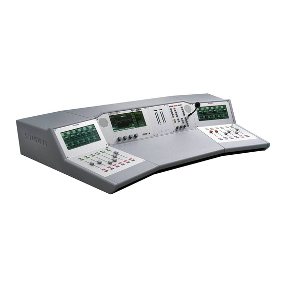
OnAir 2000M2 Digital Mixing Console INTRODUCTION OnAir 2000M2 is a smart yet powerful digital mixing console for “on-air” and small recording and editing studio applications. It has a modularity of 6 fader strips; the maximum console size is limited to 24 fader strips (ste- reo or mono). -
Page 24: Block Diagram V4.0
OnAir 2000M2 Digital Mixing Console Block Diagram V4.0 INPUTS INPUT MODULES INPUT / FADER CHANNELS CTRL I/O DC REJ Σ PROGRAM PREAMP 1 FILTER/ CHANNEL DJ MIC 1 DIG PAD (INSERT) BALANCE MUTE FADER PHASE Σ RECORD INSERT Σ AUDITION CTRL I/O N–1 A... -
Page 25: Main Outputs
OnAir 2000M2 Digital Mixing Console MAIN OUTPUTS MASTER AND MONITORING DIGITAL ANALOG METER 2 METER 1 BARGRAPH BARGRAPH METER INTERFACE SEND RETURN Σ PROGRAM ( Σ ON AIR/D) Σ PROGRAM Σ FADER ** (INSERT) LIMITER (INSERT) PFL** Σ PROGRAM/A Σ RECORD ( Σ... -
Page 26: Definition Of Terms
OnAir 2000M2 Digital Mixing Console Definition of Terms Terms used in this manual: Input: The physical input connector of the input module; standard input modules have two selectable (mono or stereo) inputs, while the hex line input mod- ules have six selectable stereo inputs. -
Page 27: General
OnAir 2000M2 Digital Mixing Console GENERAL Utilization for the Purpose Intended The OnAir 2000M2 mixing console is intended for professional use. It is presumed that the unit is operated only by trained personnel. Servicing is reserved to skilled technicians. The electrical connections may be connected only to the voltages and sig- nals designated in this manual. -
Page 28: Adjustments, Repair
Please ask your nearest Studer representative. 2.2.4 PC-Card The OnAir 2000M2 mixing console is equipped with a PC-Card socket. Using the industry-standard SRAM PC-Cards, the user can save important console information on a card. This information can then be used to restore the console to the same state at a later moment. -
Page 29: Technical Specifications
OnAir 2000M2 Digital Mixing Console Technical Specifications (subject to change without notice) General Level specs, digital, in dB dB, referenced to full modulation (dB , dB Full Scale) Level specs, analog, in dBu: 0 dBu 0.775 V Level specs, analog, in dBu... - Page 30 OnAir 2000M2 Digital Mixing Console Analog Outputs Analog output modules are available with balancing transformers or with electroni- cally balanced outputs, XLR connectors. Output level (transformer-balanced) +4 to +24 dBu @ R = 100 kΩ; = 300 Ω +4 to +23 dBu @ R...
- Page 31 OnAir 2000M2 Digital Mixing Console Dimensions: 866.7 940.5 General 2-5 Date printed: 12.11.03 SW V 4.0...
-
Page 32: Operating Concept
(e.g. equalizer parameters), or directly through the assigned touch-screen (e.g. equalizer on/off). On the screen above the fader strips, the new settings are immediately updated. The OnAir 2000M2 concept has all current settings for every channel visible at any time. This innovative user surface is called the “Touch’n’Action”... -
Page 33: Operating Elements
Ext. Supply Versions: If an OnAir 2000M2 is equipped with the optional, dual external power supply for redundancy, no power switch is at the rear of the console. In- stead, each of the two power supply units has its own power switch. -
Page 34: Central Section , Display Unit
OnAir 2000M2 Digital Mixing Console 3.1.2 Central Section , Display Unit START RESET STOP [1] Central Touch-Screen The central touch-screen display is used for parameter entries (refer to chapters 4, 5, 10, 12, and 13 for details) and displays the current time and date in digital and analog formats (except when the keyboard or routing pages are active). -
Page 35: Central Section, Monitoring And Talkback
OnAir 2000M2 Digital Mixing Console 3.1.4 Central Section, Monitoring and Talkback ON-AIR CR-MIC STUDIO-MIC AUX 2 AUX 1 EXT 3 AUDIT EXT 2 Σ REC EXT 1 Σ PGM OFF AIR N–1 B N–1 A AUX 2 AUX 1 STUDIO... - Page 36 OnAir 2000M2 Digital Mixing Console CUT: If pressed, the monitor speakers are muted, and the CUT key is illumi- nated. As long as one of the CR or DJ microphones is on, the monitor speakers are automatically muted, and the CUT key is illuminated.
-
Page 37: Fader Units
OnAir 2000M2 Digital Mixing Console 3.1.5 Fader Units ∞ ∞ ∞ ∞ ∞ ∞ [1] OFF (“key no. 3”) Keys for deactivating or activating a channel. Can be reconfigured. [2] ON (“key no. 2”) For details please refer to chapters 9 and 15.1. -
Page 38: Channel Functions
OnAir 2000M2 Digital Mixing Console CHANNEL FUNCTIONS The OnAir 2000M2 hardware is modular in groups of 6 channels; the maximum number of channels is 24. Each channel group consists of a touch-screen, 6 faders, 18 keys (3 per channel) and 6 overload indication LEDs. -
Page 39: Channel Screen
OnAir 2000M2 Digital Mixing Console Channel Screen A channel screen is located above each group of six fader strips. The channel screen has a touch matrix with 2 × 6 switch fields per fader strip as shown below. Input Selector Field... - Page 40 OnAir 2000M2 Digital Mixing Console channel (in the channel screen on the previous page: “INP 6A” at the far right,). Code 0x00000001 active: The six input selection fields are always displayed on the channel screen; the Input and AUX fields are omitted (in the channel screen below: “INP 6A...INP 6F”...
-
Page 41: Multi-Source Selector Page
OnAir 2000M2 Digital Mixing Console PAN/BAL Field: The PAN/BAL field gives an overview of the current panorama or balance setting and shows the bus assignment. The output sum symbol (Σ) is high- lighted if the channel is assigned to the program output (ΣPGM) or to the recording output (ΣREC). -
Page 42: Channel Control Page, Microphone Input
OnAir 2000M2 Digital Mixing Console 4.4.3 Channel Control Page, Microphone Input The Channel Control page for a microphone input is opened if either the AUX, the PAN, or the Input field on the channel screen is touched, pro- vided that the selected input module is a mic input. -
Page 43: Channel Control Page, Line Input
OnAir 2000M2 Digital Mixing Console 4.4.4 Channel Control Page, Line Input The Channel Control page for a line input is opened if either the AUX, the PAN, or the Input touch-screen field on the channel screen is touched, provided that the selected input module is an analog line input or a digital input. - Page 44 OnAir 2000M2 Digital Mixing Console Access Permission: Depending on the access permission (see chapter 11) of the user currently logged in, the functions not available to this user will not be displayed on the Channel Control page; an example is given below. This user cannot ac- cess the following parameters: •...
-
Page 45: Eq/Filter Page, Microphone Input
OnAir 2000M2 Digital Mixing Console 4.4.5 EQ/Filter Page, Microphone Input The EQ/Filter page for microphone input modules is opened if the EQ/Filter touch-screen field of the channel screen is touched, provided that the selected input module is a microphone input. If the user has no access permission to the EQ parameters, the EQ/Filter page will not be displayed. -
Page 46: Eq/Filter Page, Analog Line/Digital Input
OnAir 2000M2 Digital Mixing Console 4.4.6 EQ/Filter Page, Analog Line/Digital Input The EQ/Filter page for analog line and digital input modules is opened if the EQ/Filter touch-screen field on the channel screen is touched, provided that the selected input module is an analog line or digital input. If the user has no access permission to the EQ parameters, the EQ/Filter page will not be displayed at all. -
Page 47: Master Functions
OnAir 2000M2 Digital Mixing Console MASTER FUNCTIONS Master functions are not channel-related but global functions. These are audio functions (AUX master level, studio monitoring), non-audio func- tions (telephone hybrid control, clock, stopwatch), snapshot management, and system configuration. Touching one of the LOGIN, AUX & INSERT, TEL, STUDIO MON, MIXER SETUP, or HOME-CHN ON/OFF fields will always lead to the corresponding page. -
Page 48: Aux And Insert Control
OnAir 2000M2 Digital Mixing Console ministration table, his name is DEFAULT USER. The access permissions of this user can be edited. His record cannot, however, be deleted, and no password can be defined for him. AUX and Insert Control The AUX MASTER/INSERTS page is entered by touching the AUX &... -
Page 49: N-1/Audition Bus And Telephone Hybrid Control
+10 dB, the 0 dB position is marked with a dash. Two telephone hybrid units to which the clean-feeds are fed can be con- trolled from the OnAir 2000M2 user surface, if an (optional) telephone hybrid control module is installed. In such a case the ON-AIR, HOLD, and TELEPHONE fields appear on this page. -
Page 50: Additional N-1 Outputs
When upgrading from a SW version earlier than V3.0, a hardware modification is required on the DSP Board – please ask your Studer distributor for additional information. Conditions: • A Dual Analog Output Module or a Digital Output Module must be installed in order to output the four additional N–1C...F signals;... -
Page 51: Studio Monitoring
OnAir 2000M2 Digital Mixing Console The TEL/N–1/AUDIT page allows to control the N–1 outputs A and B and the audition output using the rotary encoders, as described earlier. After touching “MORE N–1”, the additional N–1 outputs (C to F) can be con- trolled, as shown below. -
Page 52: Mixer Setup
OnAir 2000M2 Digital Mixing Console Mixer Setup The Mixer Setup page gives access to several function groups used for setting the general status of the console. These are: Global snapshots, private snapshots, global microphone (mic) settings, private microphone (mic) settings, global channel routings. -
Page 53: Snapshots
OnAir 2000M2 Digital Mixing Console Snapshots A snapshot is a copy of a momentary console setup. It contains all pa- rameters (as input selection, input gain, phase, phantom power, balance or panorama setting, EQ settings, AUX settings, channel ON/OFF, and insert assignment), except fader positions and PFL. -
Page 54: Save A Snapshot To Memory
OnAir 2000M2 Digital Mixing Console 5.6.2 Save a Snapshot to Memory Saving a snapshot is done by touching a snapshot field, followed by SAVE MEM. The keyboard page appears where the snapshot name can be en- tered or edited (max. 20 characters). If the existing name is to be kept, just touch the <--¦... -
Page 55: Mic Settings
OnAir 2000M2 Digital Mixing Console Mic Settings A mic (microphone) setting is a set of parameters (EQ, gain, phantom power) for a single microphone channel. Thus, every DJ or announcer can store his preferred mic settings and recall them at any time. Up to four pri- vate mic settings for each user (max. -
Page 56: Save A Mic Setting To Memory
OnAir 2000M2 Digital Mixing Console 5.7.2 Save a Mic Setting to Memory Creating a mic setting means saving a set of equalizer and gain parameters for a single microphone channel under a given name into the console's in- ternal flash memory. This is done by first selecting the microphone chan- nel to be stored, then touching a MIC SET field, followed by SAVE MEM. -
Page 57: Routing
OnAir 2000M2 Digital Mixing Console Routing The OnAir 2000M2 features a channel router that allows to route the out- put of any input module (including the complete parameter set, as stereo mode, gain, filter, sends, bus assignment) to any fader strip. Please note that the inputs of the same input module cannot be assigned to different fader strips, as the input selector switch is located before the preamplifier. -
Page 58: Channel Routing
OnAir 2000M2 Digital Mixing Console 5.8.1 Channel Routing The channel routing, i.e. the input module-to-fader strip assignment, is accessed on the CHANNEL ROUTING page. There is only one user- specific channel routing per logged-in user available. Should the user have no access permission to the channel routing, this page is not displayed. - Page 59 OnAir 2000M2 Digital Mixing Console However, the new routing is not stored in the user's profile. When the user logs out, the temporary channel routing is lost, and his original channel routing will be loaded when logging in the next time.
- Page 60 In this moment, the audio level of an input signal may not correspond to the physical position of the new fader. As the OnAir 2000M2 does not feature motorized faders, the Auto Takeover symbol is displayed in the corresponding channel section of the fader screen.
-
Page 61: Recall A Channel Routing From Memory
OnAir 2000M2 Digital Mixing Console 5.8.2 Recall a Channel Routing from Memory Automatical Recall: Every logged-in user has his own user channel routing that is loaded either automatically when logging-in, or manually. This is defined by customer code 0x00000200 (see chapter 12.2.12). -
Page 62: Delete A Channel Routing From Memory (Administrator Only)
OnAir 2000M2 Digital Mixing Console 5.8.4 Delete a Channel Routing from Memory (Administrator Only) When saving a channel routing, the previously stored data are overwritten. A global channel routing can be deleted, too, without overwriting it by new data. To do this, first the desired channel routing has to be selected. -
Page 63: Using Pc-Cards
Notes: Using PC-Cards, it is also possible to exchange snapshot, mic setting, and/or channel routing data between OnAir 2000, OnAir 2000M2, and OnAir 1000 consoles. However, some restrictions must be considered if the consoles have different hardware configuration (e.g. number of chan- nels, number of fader strips, different input module types). -
Page 64: Save A Snapshot/Mic Setting/Channel Routing To Pc-Card
OnAir 2000M2 Digital Mixing Console 5.9.2 Save a Snapshot/Mic Setting/Channel Routing to PC-Card To save a snapshot, a mic setting, or a channel routing to a PC-Card, first select a snapshot, a mic setting, or a channel routing in the Mixer Setup page. -
Page 65: Administrator
OnAir 2000M2 Digital Mixing Console 5.10 Administrator 5.10.1 Features • The administrator has access to all private and global snapshots, mic set- tings, and channel routings. • The administrator has no private snapshots or mic settings, but one user channel routing. -
Page 66: Admin Selection Of Snapshots/Mic Settings/Channel Routings
OnAir 2000M2 Digital Mixing Console 5.10.2 Admin Selection of Snapshots/Mic Settings/Channel Routings The system administrator can display and modify the private snapshot, mic setting, and channel routing data of any user. This feature has been implemented in order to enable the setting of pa- rameters in a private snapshot, mic setting, or channel routing to which the particular user has no access. -
Page 67: Users With And Without A Password
OnAir 2000M2 Digital Mixing Console 5.10.3 Users with and without a Password When a normal user enters the Mixer Setup page before logging-in (which means he is treated as the default user), he works with the default user's data. He can LOAD, RECALL, SAVE, or DELETE all of the default user's data in the console's memory or on the PC-Card. -
Page 68: User Administration
OnAir 2000M2 Digital Mixing Console 5.11 User Administration USER ADMINISTRATION is only accessible by the system administra- tor. Refer to chapter 11 for details on how to set up function access per- mission and new user accounts. 5.12 System Configuration System configuration is a separate function group which can be accessed only by the system administrator or by users having access permission. -
Page 69: Watch And Stopwatch
OnAir 2000M2 Digital Mixing Console 5.13 Watch and Stopwatch The watch and stopwatch functions are continuously displayed on the right-hand side of the central screen (except when the keyboard or routing pages are active). The term “watch” refers to the time-of-day in analog and digital format, the day-of-week, and the date in an abbreviated format. -
Page 70: Fader Stopwatch
OnAir 2000M2 Digital Mixing Console 5.13.2 Fader Stopwatch The upper one of the two stopwatches is called the fader stopwatch. It always restarts at 00:00:00 when a new audio channel is activated (e.g. channel ON, fader open, and output bus selected). In other words, it dis- plays the elapsed time of the audio channel opened last. -
Page 71: Master Fader For Pgm And Rec Outputs
OnAir 2000M2 Digital Mixing Console 5.14 Master Fader for PGM and REC Outputs Any of the installed faders can be configured as master fader(s) for the program and/or the record bus. This selection is performed in the CHANNEL ROUTING page. Instead of a physical input module, either the... -
Page 72: Default Master Level
OnAir 2000M2 Digital Mixing Console 5.14.1 Default Master Level If a fixed level offset of the PGM and/or REC main output signal(s) is required, it is possible to enter this offset in the DEFAULT MASTER LEVEL window on the COMMON SETTINGS page in a range of –7...+5 dB. -
Page 73: Level Meters
OnAir 2000M2 Digital Mixing Console LEVEL METERS The OnAir 2000M2 mixing consoles can be equipped with one or two stereo level meters, according to customer’s specification. For the two meters, the sources can be selected in the configuration menu and are available in analog and digital (AES/EBU) form for the meters:... -
Page 74: Monitoring
OnAir 2000M2 Digital Mixing Console MONITORING Control Room Monitoring The CR monitoring source selector has 10 keys to select one out of six internal and 4 analog external sources. The key of the selected source is illuminated. The F1 to F5 keys can act as additional “to all ...” talkback target selectors... - Page 75 OnAir 2000M2 Digital Mixing Console Two additional keys are used to control the monitoring loudspeakers in the control room. The functions of these keys are described in the table below. Function Description The output level to the CR monitor loudspeakers –20 dB...
- Page 76 OnAir 2000M2 Digital Mixing Console The PFL to MONITOR function feeds the PFL signal to the monitor loud- speakers, if PFL is selected on any channel. The normal monitoring signal is muted for as long as any PFL keys are active.
-
Page 77: Studio Monitoring
OnAir 2000M2 Digital Mixing Console Studio Monitoring The built-in studio monitoring functions are based on a touch-screen menu on the control screen. The STUDIO MONITORING SOURCE page allows one of six sources to be selected for routing to the studio speakers and headphones. -
Page 78: Talkback
OnAir 2000M2 Digital Mixing Console Talkback There is a choice among several talkback targets from the DJ microphone. A key is assigned for each target as can be seen in the table below. Function Description The connection between DJ mic and Cleanfeed B TB to Tele- (N–1B, e.g. -
Page 79: Talkback Settings
OnAir 2000M2 Digital Mixing Console For ease of operation, the F1...F5 keys can also be configured as “TB FROM CR TO ALL N–1”, “TB FROM CR TO ALL AUX”, or “TB FROM CR TO ALL” (N–1 and AUX) keys. If e.g. the TB FROM CR TO ALL AUX function is configured on the F1... - Page 80 OnAir 2000M2 Digital Mixing Console Note: Configuration of talkback and signaling is also possible for analog line or digital inputs as well as for a TB mic input, as shown by the following screenshots. When installing an optional TB Mic Input module, two different cases...
-
Page 81: External Pfl
OnAir 2000M2 Digital Mixing Console External PFL The OnAir 2000M2 provides an external PFL audio input. If the EXT PFL key is pressed, the key is illuminated, and the signal at the EXT PFL input is routed to the PFL bus. A control output is activated if EXT PFL is ac- tive. -
Page 82: Signaling
OnAir 2000M2 Digital Mixing Console SIGNALING For control room and studio, signaling is provided by means of open- collector outputs (9-pin D-type “SIGN.” connector on the Monitoring module; for connection details, refer to chapter 15.13). One output is available for each of the following statuses: •... -
Page 83: Machine Control
OnAir 2000M2 Digital Mixing Console MACHINE CONTROL The OnAir 2000M2 provides different control inputs and outputs. These can be used e.g. for switching a channel on and off, or for starting, stop- ping, and cueing of the connected source unit (as CD/cartridge/MD play- ers, tape recorders, or a CAB system). - Page 84 OnAir 2000M2 Digital Mixing Console Key 3/LED 3 The functionality of the third key (labeled “OFF”) depends on the console configuration. It can act as channel OFF key or trigger a LOCATE func- tion. The key 3 functionality is set in the COMMON SETTINGS page: Console configuration (valid for all channels): Key 3 (“OFF”) function...
-
Page 85: Control Outputs
OnAir 2000M2 Digital Mixing Console Control Outputs 9.2.1 CTRL OUT1 This open-collector output is normally used to start external devices, such as CD players or a CAB system, to play the next track. On the INPUT CONFIG. page (see chapter 9.1), other functions can be assigned individu-... -
Page 86: Control Inputs
ON LAMP signal. The external command is overridden by the ON and OFF keys in the console. Additional information on this interface can be found in the circuit dia- grams chapter of the OnAir 2000M2 Service Manual. 9.3.2 EXTERN PFL Input An external PFL control input is available on the “EXT PFL CTRL”... -
Page 87: Ctrl Out1/2 & Ctrl In Application Examples
OnAir 2000M2 Digital Mixing Console CTRL OUT1/2 & CTRL IN Application Examples Configuration of Configuration Configuration Connection(s) OnAir 2000M2 key 3 Application CTRL OUT1; CTRL OUT2; –> controlled source (e.g. (“OFF”/LOCATE); see Note 4 see Note 4 CD player, cart/tape recorder... -
Page 88: Automation
Starting with software version V3.04, also a serial interface (RS232/RS422) can be used for communication with the CAB system. Studer DigiMedia System: Information on how to connect and operate the OnAir 2000M2 mixing console with a DigiMedia CAB system is given in the current DigiMedia operating instructions. -
Page 89: Application Handling
10.3.2 Communication Time-out If no valid telegram is received from the CAB within approx. 30 seconds, the OnAir 2000M2 assumes that the communication is interrupted. In this case it stops sending telegrams and the following actions are per- formed: • All channels are deselected;... -
Page 90: Output Selection
OnAir 2000M2 Digital Mixing Console 10.3.3 Output Selection The CAB is able to control the output assignment (program/record bus) of the currently selected input of any channel. This allows, for instance, to route speech to the program output, and music to the record output. -
Page 91: Indication Of The Currently Playing Input Line
OnAir 2000M2 Digital Mixing Console 10.3.5 Indication of the Currently Playing Input Line As the OnAir 2000M2 is not equipped with motor faders, a clear indicat- ion of the channel currently “playing” is visible on the screen of the CAB system. -
Page 92: User Modes
In order to satisfy these needs, the OnAir 2000M2 console supports individual user access rights. Three classes of users are defined for the OnAir 2000M2; these are: Default User: • No password required;... -
Page 93: Access Configurable Functions Of The Console
OnAir 2000M2 Digital Mixing Console 11.2 Access Configurable Functions of the Console Normal Adminis- Function Description Default User User trator Loglist management Accept an entry (delete entry from list) configurable configurable accessible View the log list accessible accessible accessible Aux Master... - Page 94 OnAir 2000M2 Digital Mixing Console Normal Adminis- Function Description Default User User trator EQ parameters: Switch EQ for this channel input on Switch EQ for this channel input off Set EQ high shelving corner freq. to low Set EQ high shelving corner freq. to high...
-
Page 95: User Administration
The described access permission allows different functionality ranges to important console functions for each user. By assigning an appropriate ac- cess permission to each user, it is possible to fit the OnAir 2000M2 con- sole to very different working environments. -
Page 96: Administration Functions
OnAir 2000M2 Digital Mixing Console 11.4 Administration Functions By the system administrator, a user record can be created (NEW), changed (EDIT), or deleted (DELETE). Create User Record: create user record, touch USER ADMINISTRATION page. The NEW USER page appears with empty in-... - Page 97 OnAir 2000M2 Digital Mixing Console user while preserving his snapshots, mic settings, and channel routings is to save them to a PC-card, delete the user, create a new one with the de- sired name, and then reload the snapshots, mic settings, and channel rout- ing from the card.
-
Page 98: Log-In Procedure And Defaults
OnAir 2000M2 Digital Mixing Console Delete User Record: To delete a user record from the user administration table, a record must be selected by touching the desired name field. A dialog box appears; if deleting the user is confirmed there, the selected user is permanently re- moved from the memory, and the user record disappears from the USER ADMINISTRATION page. - Page 99 OnAir 2000M2 Digital Mixing Console the system does not check for a password in this case, this user’s private data are not protected, and any other user can access them. If a console is operated by one person only, the system administrator sim- ply has to enable all access rights for the default user.
-
Page 100: Configuration
• Channel labels • Control signal modes • Nominal input levels • Level meter assignment, etc. An OnAir 2000M2 configuration can be stored on a PC-Card, or loaded from the PC-Card into the console. Configuration 12-1 Date printed: 12.11.03 SW V 4.0... -
Page 101: Configuration Procedure
OnAir 2000M2 Digital Mixing Console 12.2 Configuration Procedure The console configuration can be changed in the SYSTEM CONFIG. page. This page can only be reached from the Mixer Setup page by an op- erator with system administrator permission. The configuration parameters are subdivided in groups. Each group is ed- ited on a separate page accessed from the SYSTEM CONFIG. - Page 102 OnAir 2000M2 Digital Mixing Console Configuration Menu Tree Diagram: INPUT CHANNEL No./Input type INPUT A/B LABEL SIGN. TB SOURCE INPUT CONNECTOR (digital line input only) LEVEL (analog line input only) USER ADMIN. HEADROOM (analog line input only) CTRL. OUT 1 CTRL.
-
Page 103: Input
OnAir 2000M2 Digital Mixing Console 12.2.1 Input There are three slightly different INPUT CONFIG. pages for editing input configurations, depending on the type of input module identified by the hardware. The pages for microphone, analog line, and digital line inputs are shown below. - Page 104 OnAir 2000M2 Digital Mixing Console LABEL The LABEL field is used for giving a name to a channel. Touching this field, the keyboard page opens. The source label field on the channel screen can display long labels (up to 2 × 12 characters), while the input selector fields can display short labels only (up to 2 ×...
- Page 105 OnAir 2000M2 Digital Mixing Console INPUT CONNECTOR (Digital input modules only) Each (A and B) input of a digital input module has three different input connectors (XLR, RCA/Cinch, and optical/TOSLINK). This option selects independently for the A and the B inputs which connector is used.
-
Page 106: Common Settings
OnAir 2000M2 Digital Mixing Console The N–1 bus and the Audition bus output levels are controlled on the TEL/N–1/AUDIT page using the rotary encoders. For details, please refer chapter 5.3.1. When touching BACK TO CTRL OUT/IN CFG, the display switches back from the bus assignment option to the standard INPUT CONFIG. -
Page 107: Output
OnAir 2000M2 Digital Mixing Console If the OFF function is selected for the OFF key, the channel is switched off by pressing this key; if LOCATE is selected, the ON function automati- cally changes to a channel ON/OFF toggle function (also refer to chapters 9.2 and... -
Page 108: Time & Date
OnAir 2000M2 Digital Mixing Console 12.2.5 Time & Date The watch gives a time, day-of-week, and date display. The standard time reference is an internal battery-buffered real-time clock (RTC). The RTC continues to run even when the console is switched off. Therefore it is un- necessary to set the watch at power-up. -
Page 109: System Test
OnAir 2000M2 Digital Mixing Console The watch configuration is done in the TIME & DATE FORMAT page. This page is displayed after touching the “FORMAT” field on either the TIME or the DATE page. Both time and date can be displayed in two formats (select with TIME... -
Page 110: Software Update
OnAir 2000M2 Digital Mixing Console 12.2.7 Software Update More information on this subject can be found in chapter 12.2.8 Console Dump A “console dump” consists of configuration data (CONFIG. DATA), snap- shots (global and private), mic settings (global and private), and channel routings. -
Page 111: System Synchronization
OnAir 2000M2 Digital Mixing Console When loading data from the PC-Card, the console data will be overwritten. Therefore this procedure has to be confirmed in a dialog box. The EXIT field returns to the SYSTEM CONFIG. page. A Configuration is loaded into the console by selecting CONFIG. DATA, LOAD FROM PC-CARD, and EXECUTE. -
Page 112: Automation
OnAir 2000M2 Digital Mixing Console Note: The OnAir 2000M2 is designed to run at a sampling rate of 48 kHz. Due to this fact, filter parameters are accurate at 48 kHz only. If the console is synchronized to 44.1 kHz, the actual center and turnover frequencies of the EQ are lower by 8.125 %;... -
Page 113: Monitor Extension (Optional)
OnAir 2000M2 Digital Mixing Console 12.2.11 Monitor Extension (Optional) The MONITOR EXPANDER page allows to configure the functionality of the F1 to F5 keys. The different possible functions are described on the next pages and refer to the screenshot above. For additional information... - Page 114 OnAir 2000M2 Digital Mixing Console NONE If one of the F1 to F5 keys is configured to NONE, pressing this key has no effect at all – neither for the F1 to F5 output, nor for the CR source se- lection.
- Page 115 OnAir 2000M2 Digital Mixing Console TOGGLE If one of the F1 to F5 keys is configured as “TOGGLE”, the output changes its status each time the key is pressed. Neither the CR monitoring level nor the CR source selection are affected. The key LED is on for as long as the output is active.
-
Page 116: Customer Code
OnAir 2000M2 Digital Mixing Console 12.2.12 Customer Code Starting with software version 2.0.1, there is a possibility to activate op- tional, customer-specific functions as, for instance, the hex source selector fields on the touch-panel of the fader strip. For this purpose, a feature called Customer Code is used. - Page 117 OnAir 2000M2 Digital Mixing Console of a static signal at the CTRL OUT1 output when the status is activated (fader open and channel ON) and when it is de-activated (fader closed and channel OFF). Note: There is a second possibility to generate start and stop pulses without activating this customer code;...
-
Page 118: Sw Update
Control Front Board I firmware must be installed, or the Control Front Board has to be replaced. Studer will not take any responsibility nor accept warranty claims for not following this procedure. Please note that the software upgrade to V4.0 is only possible from an existing version V3.0 or later. - Page 119 OnAir 2000M2 Digital Mixing Console If your console should be equipped with an early Power Supply PCB 1.942.105.00, the smoothing capacitors C11 and C16 (22'000 µF) must be modified to 33'000 µF (order no. 59.29.0323). Otherwise, after powering the console off and on again, a warning message “Flash Verification –...
-
Page 120: Sw Update Procedure
OnAir 2000M2 Digital Mixing Console 13.2 SW Update Procedure After touching the SW UPDATE field in the SYSTEM CONFIG. page, a dialog box appears, where the user can decide whether he wants to load the software (PC-CARD), or whether he wants to stop the software update procedure (CANCEL). - Page 121 OnAir 2000M2 Digital Mixing Console Then the new software is copied from the PC-Card into the console's Flash EPROM. This will take several minutes. Finally the last dialog box appears. The system can now be re-booted (REBOOT) with the new software, or, if required and available, an op- tional customer code (CCODE) can be entered.
-
Page 122: Error Handling
OnAir 2000M2 Digital Mixing Console 13.2.1 Error Handling If the software update is interrupted by any reason, the system has to be re- booted. Afterwards, a message box appears with the message that the sys- tem software must be updated. -
Page 123: System Diagnostics And Error Handling
Failure of Restricted Functions Most of the OnAir 2000M2’s functions do not have any restriction. How- ever, there exist several functions which are restricted in some situations, e.g. loading a snapshot into a console the channel types of which do not match the ones of the snapshot (Mic/Line Inputs). -
Page 124: System Diagnostics
OnAir 2000M2 Digital Mixing Console As more than one system message can occur at the same time, the diag- nostics software manages a Log List containing one entry for each system message, completed by time and date of occurrence. If the Log List con- tains more than one entry, the PREV and NEXT fields appear on the cen- tral screen. - Page 125 OnAir 2000M2 Digital Mixing Console Diagnostics and Error Handling – System Configuration Detection Error ID Type Indication Diag. Box Error Text (Conflict) Information Module for Channels [n] - [m] installed! Information Module for Channels [n] - [m] added! Warning Module for Channels [n] - [m] removed!
- Page 126 OnAir 2000M2 Digital Mixing Console Diagnostics and Error Handling – Flash Checksum Tests Error ID Type Indication Diag. Box Error Text (Conflict) Warning Flash verification - All Snapshots, Mic Settings and Channel Routings lost due to software version mismatch! Warning...
- Page 127 OnAir 2000M2 Digital Mixing Console Snapshot Controller (cont.) Information Mic Setting not recalled due to corrupted Mic Setting Data! Information Snapshot not loaded because user [%s] (owner of the Snapshot) is not defined on this mixing console! Information Mic Setting not loaded because user [%s] (owner of the Mic...
-
Page 128: Indication On Failure Of Restricted Functions
OnAir 2000M2 Digital Mixing Console 14.2 Indication on Failure of Restricted Functions Usually, there is no indication of any error or warning if the execution of functions is prohibited in case of restrictions, because the user immediately notices whether the desired function is performed correctly. Nevertheless, some warnings need to be indicated to the user as a feedback, e.g. -
Page 129: System Test
OnAir 2000M2 Digital Mixing Console 14.3 System Test The system test can be activated by touching the SYSTEM TEST field on the SYSTEM CONFIG. page. The SYSTEM TEST selection page appears on the central screen: 14.3.1 Buttons/Faders Test Selecting the BUTTONS/FADERS test brings the console into a mode where the controls of the console can be checked. -
Page 130: Fader Calibration
OnAir 2000M2 Digital Mixing Console Channel Screen Test: If a field is touched on one of the channel screens, it is highlighted. For each fader, a bar graph indicates the current position. 14.3.2 Fader Calibration SW V1.0 through 2.01: For calibrating the fader's zero position, set all fader knobs to their “0”... -
Page 131: Display Test
OnAir 2000M2 Digital Mixing Console • Touch CAL FADER or, on the service terminal (only V2.0.1 and up), enter: call all <return>. • Close the fader(s) which just has/have been calibrated; the correspond- ing fader bar(s) on the channel screen should disappear. -
Page 132: Sw Versions Display
OnAir 2000M2 Digital Mixing Console 14.3.5 SW Versions Display When having touched SW VERSIONS, the current software versions are displayed for every module. With the PREV and NEXT fields, all available pages can be browsed. 14-10 Diagnostics SW V 4.0... -
Page 133: Hardware Modules
OnAir 2000M2 Digital Mixing Console HARDWARE MODULES 15.1 Mic Input Module 1.942.220.xx Module with two inputs and A/B input selector. Inputs A and B are trans- former-balanced mono microphone inputs. The maximum input level is such that also mono line level signals can be processed if required. - Page 134 OnAir 2000M2 Digital Mixing Console For CTRL OUT 2A/B, eight operating modes are available: NOT ACTIVE Output is always open. LOCATE KEY Output is closed (i.e. pulled to GND) when the OFF key is pressed and the channel is active.
-
Page 135: Analog Line Input Module
OnAir 2000M2 Digital Mixing Console 15.2 Analog Line Input Module 1.942.230.xx (w. transf.); 1.942.232.xx (el. bal.) The analog line input module has an input selector for two stereo input sources (A and B). Inputs A and B are equivalent. LINE The module address depends on the input channel number given to the module and is set with a DIP switch;... -
Page 136: Analog Hex Input Module
OnAir 2000M2 Digital Mixing Console 15.4 Analog Hex Input Module 1.942.245.xx (Option) The analog hex line input module has an input selector for six stereo input ANALOG IN sources (A...F). All inputs A...F are equivalent. The module address depends on the input channel number given to the module and is set with a DIP switch;... -
Page 137: Digital Hex Input Module
OnAir 2000M2 Digital Mixing Console +5 V max. 100 mA 1 +5 V SUPPLY Ω 9 COMMON 10...15 CTRL IN A...F 8 GND CTRL IN +5 V max. 100 mA 1 +5 V SUPPLY CTRL OUT max. 100 mA 2...7 CTRL OUT 2A...2F max. -
Page 138: Tb Mic Input Module
OnAir 2000M2 Digital Mixing Console 15.6 TB Mic Input Module 1.942.219.xx (Option) The TB Mic Input Module is used for connecting an internal or external talkback microphone (jumper-selectable). It offers a supply voltage for the TB MIC internal unbalanced goose-neck... -
Page 139: Telephone Hybrid Module
OnAir 2000M2 Digital Mixing Console 15.7 Telephone Hybrid Module 1.942.140.xx (Option) The telephone hybrid module is used to control two telephone hybrids from the console. TEL. HYBRID The module address must always be set to the same value by means of DIP switches;... -
Page 140: Analog Output Module
OnAir 2000M2 Digital Mixing Console 15.8 Analog Output Module 1.942.120.xx (with balancing transformers) The analog output module provides a transformer-balanced, stereo or mono output signal (jumper-selectable). LINE OUT The output signal selection is performed on the PCB by means of labeled jumpers. -
Page 141: Digital Output Module
OnAir 2000M2 Digital Mixing Console 15.10 Digital Output Module 1.942.124.xx Each digital output module delivers two independent AES/EBU output signals. The most important C-bits (Professional, Audio, Emphasis, Sam- DIGITAL OUT pling rate, Stereo) are set by the host controller. The output sampling rate is that of the console. -
Page 142: Analog Insert Module
OnAir 2000M2 Digital Mixing Console 15.11 Analog Insert Module 1.942.160.xx (Option) The analog insert module has two electronically balanced, stereo insert sends and insert returns that can be assigned to any of the input channels, INSERT or to the program or the record bus. -
Page 143: Digital Insert Module
OnAir 2000M2 Digital Mixing Console 15.12 Digital Insert Module 1.942.165.xx (Option) The digital insert module has two transformer-coupled AES/EBU insert sends and insert returns, which can be assigned to any of the input chan- INSERT nels, or to the program or the record bus. -
Page 144: Monitoring Module
OnAir 2000M2 Digital Mixing Console 15.13 Monitoring Module 1.942.134.xx /1.942.180.xx The monitoring module is a (mainly analog) monitoring unit. It has five external analog inputs in addition to the console’s internal buses. It pro- vides analog output signals for headphones and loudspeakers in the control room and the studio. - Page 145 OnAir 2000M2 Digital Mixing Console Pin Assignments: CR OUT L/R (XLR, 3pin, male): Signal Chassis Output + Output – EXTERN MONITOR INPUT (39-pin Siemens, male): Signal Signal Signal EXT1 + left EXT1 – left Chassis EXT1 + right EXT1 – right...
- Page 146 OnAir 2000M2 Digital Mixing Console STUDIO MON CTRL (D-type, 25 pin, male): Signal Signal Signal +5 V SUPPLY Lamp EXTERN Switch TB TO TEL2 COMMON Spare OUT2 Lamp PGM Switch AUX1 n.c. Lamp AUX2 Switch OFF AIR Lamp PFL Switch EXTERN...
- Page 147 OnAir 2000M2 Digital Mixing Console EXT PFL CTRL (D-type, 9 pin, male): Signal Signal +5 V SUPPLY External PFL IN + External PFL IN – n.c. / External TB to CR – (note 1) External PFL OUT Spare OUT External TB COMMON + (note 1) n.c.
- Page 148 OnAir 2000M2 Digital Mixing Console SIGN. (D-type, 9 pin, male): Signal Signal +5 V SUPPLY COMMON ON AIR IN – Spare IN – or Ext. CR DIM IN – * CR MIC OUT STUDIO MIC OUT PGM OUT Spare OUT * depending on Customer Code setting 1 k Ω...
- Page 149 OnAir 2000M2 Digital Mixing Console CTRL (D-type, 9 pin, male): This connector provides all the signals required for a guest headphone. The “Phones OUT” signal is the same as the one on the GUEST jack socket on the same module.
-
Page 150: Monitoring Module W. Extension
OnAir 2000M2 Digital Mixing Console 15.14 Monitoring Module w. Extension 1.942.138.xx/1.942.181.xx (Option) The monitoring module can be extended in two stages; in both cases, the basic functions of the monitoring module as described in chapter 15.13 will be maintained. The basic unit can be extended by one or two PCBs; in addition, a modified connector panel is required as well. - Page 151 OnAir 2000M2 Digital Mixing Console EXTENSION CTRL 1 (D-type, 15pin, male): Signal Signal Signal 1 2 3 4 5 6 7 8 +5V SUPPLY CTRL OUT 4 OPTO IN 2 COMMON CTRL OUT 5 OPTO IN 3 CTRL OUT 1...
- Page 152 On-Air 2000M2 Digital Mixing Console Monitor Extension Block Diagram INTERCONNECTION BOARD 1 - BOARD 2 MONITOR EXPANDER BOARD 1 MONITOR EXPANDER BOARD 2 1.942.136.21 1.942.137.00 EXTERN MONITOR INPUT EXTENSION EXT 3_L J102 EXT_7 digital 9 a/b EXT 3_R J100 EXT_8 digital 10 a/b CR_MON_L CR_MON_R...
-
Page 153: Serial Interface Module
Note 2: RTS and CTS are connected internally 15.16 Clock Sync Module 1.942.135.xx (Option) The OnAir 2000M2 console can be equipped with a clock sync module which allows the console to be synchronized to external clock sources. SYNC Synchronizing to the following external signals is provided: AES/EBU 32 kHz, 44.1 kHz, 48 kHz;... -
Page 154: Time Sync Module
OnAir 2000M2 Digital Mixing Console 15.17 Time Sync Module 1.942.150.xx (Option) With a time sync module, the console's internal clock can be synchronized to an external time reference unit, such as a DCF77 or GPS receiver, or a TIME SYNC Mobatime clock providing a serial output signal. -
Page 155: Dip Switches And Jumpers
OnAir 2000M2 Digital Mixing Console DIP SWITCHES AND JUMPERS Note: The DIP switch and jumper positions are printed on the PCBs, except for the TB Mic Input Module and the Analog Output Module; for these two assemblies, drawings have been included in the following chapters for component location. -
Page 156: Tb Mic Input Module
OFF ON EXT TB CTRL Jumper for Module Position: When installing the TB Mic Input Module in an OnAir 2000M2 console, the console configuration must be updated. 6-Channel Console • Configure as 12-channel console (on DSP Board: only CFG1 inserted). - Page 157 OnAir 2000M2 Digital Mixing Console 24-Channel Console • One of the input modules being already installed must be sacrificed when installing a TB Mic Input Module. • Make sure that the correct address is set on the TB Mic Input Module;...
- Page 158 OnAir 2000M2 Digital Mixing Console TB OUT UNBAL AGND AGND EXT INT INT ELEC- TRET MIC AGND AGND EXT MIC EXT TB AGND CTRL TB OUT BAL IN B AGND IN A INSIG_N OUT B INSIG_P OUT A EXT_VCC OUTPUT...
-
Page 159: Telephone Hybrid Interface
OnAir 2000M2 Digital Mixing Console 16.3 Telephone Hybrid Interface The DIP Switch on the Telephone Hybrid Control Module must always be set as follows: DIP switch no.: OFF OFF 16.4 Analog Output Module The Analog Output Module has labeled jumpers located on the PCB for mono/stereo selection and output signal selection. -
Page 160: Digital Output Module
OnAir 2000M2 Digital Mixing Console OUTPUT LEVEL A RIGHT Dual Analog Output Module 1.942.121. 82 OUTPUT LEVEL A LEFT OUTPUT LEVEL OUTPUT LEVEL B RIGHT B LEFT B STEREO B MONO 16.6 Digital Output Module Digital Output Modules have two DIP switches (A and B) for output signal selection for each of the two independent outputs A and B. -
Page 161: Monitoring Module
On-Air 2000M2 Digital Mixing Console 16.8 Monitoring Module On the Monitoring Controller PCB, all DIP switches must be set to their OFF position. 16.9 Clock Sync Module If P7 and P8 are connected with a jumper, the 75 Ω termination of the VIDEO IN input is active. -
Page 162: Console Size Selection
OnAir 2000M2 Digital Mixing Console DIP Switch: OFF ON 4 5 6 7 8 9 12 10 Time Sync Module 16.11 Console Size Selection Jumper Setting The console size must be set with the two jumpers CFG0 (P20-P23) and CFG1 (P21-P24) on the DSP board (1.942.102.xx):... -
Page 163: Index
OnAir 2000M2 Digital Mixing Console INDEX Central Touch-Screen ........... 3-3 Change User Record ........... 11-5 Access Permission ..........4-6 CHANNEL ............12-4 Access Rights............5-19 Channel Control page ........4-5, 4-6 Additional N–1 Outputs........5-4 Channel Functions ..........4-1 Additional Talkback Functions......7-5 channel key functions ........... - Page 164 OnAir 2000M2 Digital Mixing Console CTRL OUT ..........15-4, 15-5 EQ/Filter page ..........4-8, 4-9 CTRL OUT 1 ..........9-1, 9-3 Error ..............14-1 CTRL OUT 1A/B..........15-1 Error Handling .......... 13-5, 14-1 CTRL OUT 2 ..........9-1, 9-3 Error messages ............14-1 CTRL OUT 2A/B..........15-2...
- Page 165 OnAir 2000M2 Digital Mixing Console Hardware Modules..........15-1 LABEL............12-4, 12-5 Hardware Performance Check ......14-2 LC display............. 3-6 Headphones............3-5 Leitch ............15-22, 16-7 headroom ....... 4-1, 12-4, 12-6, 15-1, 15-10 LEVEL............12-4, 12-6 Hex Input Selection .......... 12-17 Level Meter.......... 3-3, 6-1, 12-8 High Shelving Filter..........
- Page 166 OnAir 2000M2 Digital Mixing Console mono/stereo selection..........16-5 PFL > MON ..........3-5, 7-3 month..............12-9 PFL CUT ON CH. ACTIVE .......12-7 Multi-Source Selector Page........4-4 PFL function............9-1 PFL to MONITOR ..........7-3 PFL/TB..............3-5 PFL/TB loudspeakers........3-5, 7-5 N–1................3-5 PFL/TB speakers...........3-5 N–1 A ............3-5, 5-3 PHANTOM ............4-5...
- Page 167 OnAir 2000M2 Digital Mixing Console Save a Mic Setting ..........5-10 talkback target keys..........7-5 Save a Snapshot ............ 5-8 talkback targets ..........3-5, 7-5 Save a Snapshot/Mic Setting ......5-18 tape recorders............9-1 SAVE CARD ............5-18 TB FROM CR TO..........12-16 SAVE MEM ..........5-8, 5-10...
- Page 168 OnAir 2000M2 Digital Mixing Console WCLK OUTPUT ..........15-21 Word clock ..........12-12, 15-21 VIDEO ..............12-12 VIDEO IN ............15-21 Video sync............15-21 viewing angle ............3-6 year ..............12-9 volume control ..........7-2, 7-3 Z... Vortex..............16-7 ΣPGM............3-4, 7-1 ΣPROGRAM..........4-5, 4-6 Warning...............14-1 ΣREC............. 3-4, 7-1 watch ..............5-23...
- Page 169 OnAir 2000M2 Digital Mixing Console CONTENTS PART TWO – SERVICE INSTRUCTIONS Features..................................1-1 System Architecture..............................1-1 Signal Processing..............................1-2 Audio Buses................................1-3 Host Controller ................................ 1-3 Hardware ..................................2-1 Input Modules................................2-2 Output Modules ............................... 2-2 Monitoring ................................2-2 Touch Screens................................2-4 User Surface ................................
- Page 170 OnAir 2000M2 Digital Mixing Console Service Terminal ................................5-1 Connecting Cable ..............................5-2 SW Update via the Service Terminal ........................5-3 Service Terminal Commands and Examples ......................5-4 Spare Parts ...................................6-1 0-2 Contents SW V4.0 Date printed: 12.11.03...
- Page 171 OnAir 2000M2 Digital Mixing Console FEATURES • Fully digital mixing console • Touch-screen based user interface (“Touch’n’action”) • Context-sensitive rotary encoders with tactile feedback • 6, 12, 18, or 24 channels • Flexible configuration • Snapshots • PC-Cards for snapshots, configuration, and software update •...
- Page 172 OnAir 2000M2 Digital Mixing Console Signal Processing 1-2 Features SW V4.0 Date printed: 12.11.03...
- Page 173 OnAir 2000M2 Digital Mixing Console The signal processing is based on 24-bit DSPs from Texas Instruments (TMS57070). The input channels are processed by 12 DSPs (i.e. two stereo channels per DSP. The summing bus is a PLD (programmable logic device) design and can handle up to 32 bit. The resulting sums are further processed by three additional DSPs.
- Page 174 OnAir 2000M2 Digital Mixing Console HARDWARE 866.7 940.5 Hardware 2-1 Date printed: 28.10.2005 SW V4.0...
- Page 175 15 and Restrictions: The maximum number of inputs on the OnAir 2000M2 is limited to 64. Therefore a 12-channel console can be equipped with a maximum of 10 Hex Input Modules (10 × 6 inputs) plus e.g. two Mic Input Modules (2 × 2 inputs).
- Page 176 OnAir 2000M2 Digital Mixing Console MAIN OUTPUTS MASTER AND MONITORING DIGITAL ANALOG METER 2 METER 1 BARGRAPH BARGRAPH METER INTERFACE SEND RETURN Σ PROGRAM ( Σ ON AIR/D) Σ PROGRAM Σ FADER ** (INSERT) LIMITER (INSERT) PFL** Σ PROGRAM/A Σ RECORD ( Σ...
- Page 177 OnAir 2000M2 Digital Mixing Console Touch Screens Each of the LC displays has a resolution of 640 × 200 pixels. A cold cath- ode fluorescent lamp (CFL) provides the back light, having a typical life- time (50% brightness) of 10'000 to 15'000 hours (meaning about 13 to 20 months of continuous operation).
-
Page 178: Power Supply
The secondary Power Supply (1.942.105.xx) generates all required volt- ages for the console except the +48 V phantom power, which is generated on the Controller Board. Power consumption of an OnAir 2000M2/24/4 console is about 150 VA. Hardware 2-5 Date printed: 12.11.03... - Page 179 OnAir 2000M2 Digital Mixing Console Redundant Power Supply (optional) The optional external power supply unit for the OnAir 2000M2 console is installed in a 19” 2U housing. Two of these supply units are used if redun- dancy is desired (order no. 1.942.109.00). In such a case, the internal power supply of the console is replaced by a connection unit equipped with two 30-pin Siemens connectors.
- Page 180 Channel n The number of N–1 buses is limited by the maximum number of output buses which can be handled by the signal processing. The OnAir 2000M2 has two N–1 buses (N–1A, N–1B), and four additional N–1C...F buses available as an option. All of them are mono buses.
- Page 181 0x81 and 0x86 (hex). The module with address 0x81 is always controlled by the leftmost channel strip. For details, refer to chapter 16 of the OnAir 2000M2 Operating Instruc- tions. 3-2 Configuration SW V4.0 Date printed: 12.11.03...
- Page 182 For details, please refer to chapters 5.3.1 16.5 of the OnAir 2000M2 Operating Instructions. When using the additional cleanfeed outputs, no Insert 3/4 can be installed in the console. Digital Output Modules have two independent digital outputs conforming to the AES3-1992 stan- dard.
- Page 183 OnAir 2000M2 Digital Mixing Console ALIGNMENT There are only few elements in the OnAir 2000M2 requiring adjustment. Power Supply The +5 V (digital) is the only voltage which can be aligned. Procedure Measure the +5 V supply between pin1 and pin3 of P19 on the DSP board according to the drawing below.
- Page 184 OnAir 2000M2 Digital Mixing Console Level Meters • Feed a test signal with your particular nominal level (e.g. +6 dBu) to an analog or digital line input. • Set the fader of the corresponding channel to the 0 dB position.
-
Page 185: Output Levels
OnAir 2000M2 Digital Mixing Console Output Levels 4.3.1 Analog Output Module 1.942.120/.122 • Feed a test signal with your particular nominal level (e.g. +6 dBu) to the input of an analog or digital line input module. • Set the fader of the corresponding channel to the 0 dB position. - Page 186 OnAir 2000M2 Digital Mixing Console 4.3.2 Dual Analog Output Module 1.942.121 Notes: Trimmer potentiometer locations are different for the two PCB versions ...81 and ...82, as indicated in the two drawings below. • Feed a test signal with your particular nominal level (e.g. +6 dBu) to the input of an analog or digital line input module.
- Page 187 IN1...8: Address selection – please refer to the “Jumper for Module Position” paragraph in chapter 16.2 of the OnAir 2000M2 Operating Manual; fac- tory setting: IN2. Settings: MIC GAIN: Depending on the output level of the microphone used, the limiter thresh- old is adjusted with the MIC GAIN trimmer potentiometer (RA1).
- Page 188 OnAir 2000M2 Digital Mixing Console on the PCB), and the MIC GAIN trimmer potentiometer is adjusted to a level just below the point where no more output level increase is meas- ured. If an other microphone is used, the appropriate input connector, jumper settings and input signal level must be used.
- Page 189 OnAir 2000M2 Digital Mixing Console SERVICE TERMINAL A service terminal connector is provided for servicing the OnAir 2000M2. The Service Terminal Task enables the user to bypass the “normal” user interface and approach the system in a more direct way. This is used in...
- Page 190 OnAir 2000M2 Digital Mixing Console Connecting Cable The terminal is connected to the 10-pin header connector (P13) labeled “SERVICE TERMINAL” on the Controller Board. The connecting cable is a straight 10-pin header to 9-pin D-type cable, where wire no. 10 is not used at the D-type connector side;...
- Page 191 OnAir 2000M2 Digital Mixing Console The following terminal settings must be used: SW Update via the Service Terminal Procedure Dump all snapshots, mic settings, and configuration data to a PC-Card or to the service terminal (refer to chapter “Dump mode”).
- Page 192 OnAir 2000M2 Digital Mixing Console If the Admin Password is Lost Recommended Procedure After entering the following commands (each followed by ENTER): debug disp Ø a listing as given below will appear: By entering characters from 1 to 20, the access permission of each user...
- Page 193 OnAir 2000M2 Digital Mixing Console Service Terminal Commands User P: Processing Command Syntax Impl. mode H: Header of next line (Level) Debug user P: enter extended (Debug) User Mode ServIf:\>deb[ug] Service mode H: ServIf:\debug> Back to the Service or P: return to Service User Mode next higher ServIf:\debug>..
- Page 194 OnAir 2000M2 Digital Mixing Console User P: Processing Command Syntax Impl. mode H: Header of next line (Level) P: enter Display Mode Display mode ServIf:\debug>disp[lay] Debug H: ServIf:\disp> Display P: Structure and display the desired part of CC on the Service global console ServIf:\debug\disp>gcc...
- Page 195 OnAir 2000M2 Digital Mixing Console User P: Processing Command Syntax Impl. mode H: Header of next line (Level) ServIf:\>dump P: enter Display Mode Dump mode Debug ServIf:\debug>dump H: ServIf:\dump> ServIf:\>dump Service or P: enter Dump Mode Dump Mode ServIf:\debug>dump Debug H: ServIf:\dump>...
- Page 196 OnAir 2000M2 Digital Mixing Console User P: Processing Command Syntax Impl. mode H: Header of next line (Level) P: enter Filter Mode ServIf:\>filt[er] Service or Filter Mode H: ServIf:\filter> ServIf:\debug>filt[er] Debug H: ServIf:\debug\filter> Display Filter ServIf:\filter>? Service or P: displays filter settings for error/warning/information Settings ServIf:\debug\filter>?
- Page 197 OnAir 2000M2 Digital Mixing Console User P: Processing Command Syntax Impl. mode H: Header of next line (Level) Post Message P: enter Post Message Mode ServIf:\debug>msend Debug Mode H: ServIf:\debug\msend> Post Message P: enter Post Message Taskname Mode ServIf:\debug\msend>taskname Debug Task Mode H: ServIf:\debug\msend\taskname>...
- Page 198 OnAir 2000M2 Digital Mixing Console User P: Processing Command Syntax Impl. mode H: Header of next line (Level) Send Telegram P: enter Telegram Send Mode ServIf:\debug>tsend Debug Mode H: ServIf:\debug\tsend> Send Telegram P: enter Send Telegram Busid Mode ServIf:\debug\tsend>busid name...
- Page 199 OnAir 2000M2 Digital Mixing Console User P: Processing Command Syntax Impl. mode H: Header of next line (Level) Memory Mode ServIf:\debug>mem Debug P: enter Memory ModeH: ServIf:\debug\mem> Display ServIf:\debug\mem> P: display memory at address 0x01234567 Debug Memory Mode 0x01234567_ H: ServIf:\debug\mem>0x01234567_0x00...
- Page 200 OnAir 2000M2 Digital Mixing Console Examples of Service Terminal Commands 5.5.1 Displaying the List of Basic Commands (?) ServIf:\> ServIf:\>? Orthography : ============= Service-Monitor operation is modelled on DOS-Command and -Directory Structure. - command-line-header indicates the state(-level) - several commands (separated by ‘ ‘ or ‘\’) are possible - if a command is not finished, then the next level is achieved - ‘..’...
- Page 201 OnAir 2000M2 Digital Mixing Console 5.5.2 Displaying the Console Configuration Header (CCH) ServIf:\debug\disp> ServIf:\debug\disp>cch CONSOLE CONFIGURATION HEADER : ============================== SW-Version V2.0.2b 24.11.1998 Number of Channels Checksum 0xfb8e 5.5.3 Displaying the Global Console Configuration (GCC) ServIf:\debug\disp> ServIf:\debug\disp>gcc GLOBAL CONSOLE CONFIGURATION :...
- Page 202 OnAir 2000M2 Digital Mixing Console 5.5.4 Displaying the Administrator's Configuration Data (UC 0) ServIf:\debug\disp> ServIf:\debug\disp>uc ServIf:\debug\disp\uc:userID>0 USER CONFIGURATION : userID ===================== User Name ADMIN User Password ‘ADMIN’ Accept Error allowed Insert allowed Aux Send allowed Audition Level allowed N-1 Level allowed...
- Page 203 OnAir 2000M2 Digital Mixing Console 5.5.6 Displaying the Configuration Data of a Normal User (e.g. UC 2) ServIf:\debug\disp> ServIf:\debug\disp>uc ServIf:\debug\disp\uc:userID>2 USER CONFIGURATION : userID ===================== User Name JACKIE B. User Password ‘FILOU’ Accept Error allowed Insert allowed Aux Send allowed...
- Page 204 OnAir 2000M2 Digital Mixing Console SPARE PARTS [10] [19] [17] [14] [11] [15] [18] [12] [16] [13] OnAir 2000 OnAir 2000M2 OnAir 2000M2 Item (dark version) (bright version) Modulo Designation Order No.: Order No.: Order No.: 1.942.020.14 1.942.021.14 Side panel, left 1.942.020.06...
- Page 205 OnAir 2000M2 Digital Mixing Console 1.942.096.00 (one set per unit): Accessory Sets: consisting of: Mains cable socket IEC320 Mains cable strain relief 14 connectors XLR3f 3 connectors D-type f, 9 pin, with cover 1 connector D-type f, 25 pin, with cover...
- Page 206 1.942.600.20 1.942.601.20 DSP Board 1.942.102.22 Control Front Board I (for earlier OnAir 2000 versions) 1.942.110.22 1.942.110.22 1.942.110.20 1.942.110.20 Control Front Board I (for OnAir 2000M2 versions) 1.942.610.20 1.942.610.20 Control Front Board II 1.942.111.00 Control Front Board III 1.942.112.00 Assembly Component...
- Page 207 OnAir 2000 Digital Mixing Console Assembly Component Level Meter Diagram Parts List Layout Level Meter Interface 1.942.113.21 Dual Bargraph PPM (optional) 1.913.111 Dual Bargraph VU (optional) 1.913.112 Dual 30-LED PPM (optional) 1.913.105 Dual 30-LED VU (optional) 1.913.106 Correlator, 30-LED, switchable 1/2 1.913.100.00 Correlator, 30-LED 1.913.109.00...
- Page 208 OnAir 2000 Digital Mixing Console System Wiring (for a 6-Ch Console, w. Optional Input Module Extension Box) Section 1 Date printed: 12.11.03...
- Page 209 OnAir 2000 Digital Mixing Console System Wiring (for a 6-Ch Console, w. Ext. Supply Option) Section 1 Date printed: 12.11.03...
- Page 299 OnAir 2000 Digital Mixing Console Power Supply 1.942.105.84 ( 0) Section 1 Date printed: 09.02.04...
- Page 300 OnAir 2000 Digital Mixing Console Power Supply 1.942.105.84 ( 0) Section 1 Date printed: 09.02.04...
- Page 301 OnAir 2000 Digital Mixing Console Power Supply 1.942.105.84 ( 0) Page: 1 of 1 Idx. Pos. Part No. Qty. Type/Val. Description Idx. Pos. Part No. Qty. Type/Val. Description 54.12.0503 1 pce Power-Pin Stecker 59.60.3315 1 pce CER 50V, 10%, X7R, 0805 not used 1 pce Jumper...
- Page 370 OnAir 2000 Digital Mixing Console CONTENTS PART FOUR – DIAGRAMS FADER SECTION Assembly Component Input Modules Diagram Parts List Layout Block Diagram Mic Input Module Mic Input Module 1.942.220.23 Insert Send 1.942.221.00 Block Diagram Line Input Module Line Input Module with Transformer 1.942.230.22 1.942.230.22 1.942.230.21...
- Page 412 OnAir 2000 Digital Mixing Console CONTENTS PART FIVE – ACCESSORIES Assembly Component Talkback Box Diagram Parts List Layout Studio Talkback Box 1.924.555 1.925.555.00 TB Box Board 1.924.551.00 1.924.550.00 1.924.551.00 1.924.551.00 Connecting Cable to above 1.925.555 1.925.555.00 1.925.555.00 Assembly Component Fader Start Control Diagram Parts List Layout...
- Page 427 External Supply Unit for Studer OnAir 2000 Mixing Console Operating and Service Instructions...
- Page 428 External PSU for OnAir 2000 CONTENTS External PSU for OnAir 2000............................3 Utilization for the Purpose Intended ..........................3 First Steps ..................................3 1.2.1 Unpacking and Inspection............................ 3 1.2.2 Installation ................................3 Adjustments, Repair ..............................4 Wiring and Hardware Information ..........................5 Setup ....................................
-
Page 429: External Psu For Onair 2000
External PSU for OnAir 2000 EXTERNAL PSU FOR ONAIR 2000 Utilization for the Purpose Intended The External Power Supply Unit (PSU) for Studer OnAir 2000 and OnAir 2000M2 mixing consoles with redundant supply option is intended for pro- fessional use. - Page 430 Replacing the supply unit: The primary fuses are located within the primary power supply units and cannot be changed. In case of failure, the complete supply unit must be re- placed. Please ask your nearest Studer representative. E4 External PSU Date printed: 12.11.03...
-
Page 431: Wiring And Hardware Information
+ miscellaneous mounting hardware *** Earlier versions only: The Power Supply PCB 1.942.105.83 for OnAir 2000M2 Modulo devices requires an additional capacitor in paral- lel with C11 and C16, due to the increased current drawn by the additional Remote Master and Slave PCBs. This capacitor is referenced with “C*”... -
Page 432: Setup
External PSU for OnAir 2000 either one or two LEDs – preferably flashing types, with integrated current limiting resistors for 5 V operation. For connection, please refer to the diagram below. P8/1 ALARM_1 P8/2 ALARM_2 P8/3 +5 V P8/4 Resistor value(s) DGND depending on LED operating... -
Page 433: Diagrams
External PSU for OnAir 2000 DIAGRAMS Assembly Component Diagram Parts List Layout OnAir 2000/2000M2 wiring diagram w. power supply redundancy option External PSU wiring diagram 1.918.220/222* .00/.81/.82 External PSU spare parts diagram 1.918.220/222* .00/.81/.82 Power Supply PCB 1.942.105 .83/.84 .83/.84 .83/.84 Sub Board for PSU 1.918.221... - Page 434 External PSU for OnAir 2000 OnAir 2000/2000M2 Wiring Diagram with Power Supply Redundancy Option E8 External PSU Date printed: 12.11.03...
- Page 441 OnAir 2000 Digital Mixing Console Power Supply 1.942.105.84 ( 0) Date printed: 23.08.04...
- Page 442 OnAir 2000 Digital Mixing Console Power Supply 1.942.105.84 ( 0) Date printed: 23.08.04...
- Page 443 OnAir 2000 Digital Mixing Console Power Supply 1.942.105.84 ( 0) Page: 1 of 1 Idx. Pos. Part No. Qty. Type/Val. Description Idx. Pos. Part No. Qty. Type/Val. Description 54.12.0503 1 pce Power-Pin Stecker 59.60.3315 1 pce CER 50V, 10%, X7R, 0805 not used 1 pce Jumper...
Need help?
Do you have a question about the OnAir 2000M2 and is the answer not in the manual?
Questions and answers