Studer OnAir 3000 Operating Instructions Manual
Digital mixing console
sw version 3.0
Hide thumbs
Also See for OnAir 3000:
- Operating instructions manual (434 pages) ,
- Service instructions manual (352 pages)
Table of Contents
Advertisement
Quick Links
Advertisement
Chapters
Table of Contents

Related Manuals for Studer OnAir 3000


Summary of Contents for Studer OnAir 3000
- Page 1 Studer OnAir 3000 Digital Mixing Console SW Version 3.0 Operating Instructions...
- Page 2 Copyright by Studer Professional Audio GmbH Studer Professional Audio GmbH Printed in Switzerland Order no. BD10.275140-8 (0309) Technical Documentation Althardstrasse 30 CH-8105 Regensdorf – Switzerland http://www.studer.ch Subject to change Studer is a registered trade mark of Studer Professional Audio GmbH, Regensdorf...
-
Page 3: Safety Information
Safety Information Safety Information To reduce the risk of electric shock, do not remove covers (or back). No user-serviceable parts inside. Refer servicing to qualified service person- nel. This symbol is intended to alert the user to presence of un-insulated dan- gerous voltage within the equipment that may be of sufficient magnitude to constitute a risk of electric shock to a person. - Page 4 Installation General Installation Hints Please consider besides these general hints also any product-specific hints in the "Installation" chapter of this manual. Unpacking Check the equipment for any transport damage. A unit that is mechanically damaged or that has been penetrated by liquids or foreign objects must not be connected to the AC power outlet or must be immediately disconnected by unplugging the power cable.
- Page 5 Installation Class I Equipment (Mains Operation) Should the equipment be delivered without a matching mains cable, the latter has to be prepared by a trained person using the attached female plug (IEC320/C13 or IEC320/C19) with respect to the applicable regulations in your country.
- Page 6 Installation/Maintenance/ESD tor) and that also takes into consideration the EMC requirements. When deciding between radial, surface, or combined grounding, the advan- tages and disadvantages should be carefully evaluated in each case. • Use shielded cables where shielding is specified. The connection of the shield to the corresponding connector terminal or housing should have a large surface and be corrosion-proof.
- Page 7 ESD/Repair material in which the replacement assembly was shipped. If this should not be the case, any claim for a possible refund will be null and void. • Unpacked ESD sensitive components should only be handled in ESD protected areas (EPA, e.g. area for field service, repair or service bench) and only be touched by persons who wear a wristlet that is connected to the ground potential of the repair or service bench by a series resistor.
- Page 8 Repair/Disposal SMD Components Studer does not keep any commercially available SMD components in stock. For repair the corresponding devices should be purchased locally. The specifications of special components can be found in the service man- ual. SMD components should only be replaced by skilled specialists using ap- propriate tools.
- Page 9 CE Declaration of Conformity Studer Professional Audio GmbH, CH-8105 Regensdorf, declare under our sole responsibility that the product Studer OnAir 3000, Digital Mixing System (starting with serial no. 1001) to which this declaration relates, according to following regulations of EU directives and amendments •...
- Page 10 Ambient Temperature Units and systems by Studer are generally designed for an ambient tem- perature range (i.e. temperature of the incoming air) of +5...+40 °C. When rack mounting the units, the intended air flow and herewith adequate cool- ing must be provided.
- Page 11 Appendix Before putting into operation, the system must be checked for internal for- mation of condensation or ice. Only with a minute formation of ice, direct evaporation (sublimation) may be expected; otherwise the system must be heated and dried while switched off. A system without visible internal formation of ice or condensation should be heated up with its own heat dissipation, as homogeneously (and subse- quently as slow) as possible;...
- Page 12 Appendix Appendix 2: Mains Connector Strain Relief For anchoring connectors without a mechanical lock (e.g. IEC mains con- nectors), we recommend the following arrangement: The cable clamp shipped with your unit is auto-adhesive. For mounting Procedure: please follow the rules below: •...
- Page 13 The following Terms and Conditions grant the right to use all programs of License Programs of Studer Studer that are part of the System and/or its options at the time of its deliv- ery to the Customer, as well as the installation software on the original data disk and the accompanying documentation (“License Material”).
- Page 14 Reverse engineering is only permitted with the express consent of Studer. Reverse Engineering The consent of Studer can be obtained but is not limited to the case in which the interface-software can not be provided by Studer. In any case Studer has to be informed immediately upon complete or partial reverse engineering.
- Page 15 OnAir 3000 Digital Mixing Console WIRING – IMPORTANT The OnAir 3000 RS422 and Ethernet wiring must comply with the following requirements: Cable Type: Cat 5e, with shielded connectors on both ends. Cable Dimensions: Max. Length Max. Length for Min. Min.
- Page 16 OnAir 3000 Digital Mixing Console Important SW V2.0 Date printed: 18.01.08...
-
Page 17: Table Of Contents
Desk Surface ................................4-2 4.2.1 System Wiring OnAir 3000 Modulo ........................4-2 4.2.2 System Wiring OnAir 3000, Fixed-Frame Version .................... 4-3 Fader Module, LED Version ............................. 4-4 Fader Module, OLED Version ..........................4-7 Fader Assign Module .............................. 4-10 Channel Screen ............................... 4-10 Rotary Module ................................ - Page 18 OnAir 3000 Digital Mixing Console 5.3.3 Channel Page..............................5-7 5.3.3.1 (Channel) Input Page..............................5-7 5.3.3.2 (Channel) De-Esser Page ............................5-14 5.3.3.3 (Channel) Equalizer Page............................5-15 5.3.3.4 (Channel) Dynamics Page ............................5-16 5.3.3.5 (Channel) Subgroup Dynamics (optional) ........................5-18 5.3.3.6 (Channel) AUX Page ..............................5-20 5.3.3.7...
- Page 19 OnAir 3000 Digital Mixing Console 5.7.7.2 Desk Power-up ................................5-78 5.7.7.3 System Power-up................................. 5-78 5.7.8 User Warnings ..............................5-79 Routing..................................5-80 5.8.1 Audio Routing..............................5-80 5.8.1.1 Physical Audio Inputs and Outputs ..........................5-81 5.8.1.2 Logical Audio Inputs..............................5-81 5.8.1.3 Logical Audio Outputs ..............................5-82 5.8.2...
- Page 20 OnAir 3000 Digital Mixing Console Configuration .................................. 6-1 Auto Config ................................6-2 6.1.1 I/O Init................................6-3 6.1.1.1 Logical Inputs................................6-3 6.1.1.2 Talkback Inputs ................................6-4 6.1.1.3 Patch Inputs ................................... 6-4 6.1.1.4 Strip Assignment ................................6-4 6.1.1.5 CR and Studio1 Monitoring Outputs ..........................6-4 6.1.1.6...
- Page 21 OnAir 3000 Digital Mixing Console 6.5.22.2 Rotary ..................................6-49 6.5.22.3 SP SRC..................................6-50 6.5.23 Signaling ................................6-51 6.5.23.1 Settings ..................................6-51 6.5.24 Snapshot ................................6-52 6.5.20.1 Parameters ................................... 6-52 6.5.25 TalkBack ................................6-53 6.5.25.1 Settings ..................................6-53 6.5.25.2 TalkBack..................................6-54 6.5.26...
- Page 22 Canonical Names ............................... 9-2 9.2.3 Network Routing..............................9-2 9.2.4 Network Bandwidth ............................9-3 9.2.5 Network Topology.............................. 9-3 9.2.6 OnAir 3000 Component Packet Types....................... 9-3 9.2.7 Traffic Shaping..............................9-4 9.2.8 IP Filtering ................................ 9-4 9.2.9 Mixed Mode ............................... 9-4 9.2.10 Firewall ................................9-4 9.2.11...
-
Page 23: Introduction
OnAir 3000 Digital Mixing Console INTRODUCTION The Studer OnAir 3000 digital mixing console is based on a DSP core (Com- pact SCore or SCore Live) and the D21m I/O platform, together with the dedicated OnAir 3000 desk modules. The DSP core includes the digital signal processing. Audio interfacing is... -
Page 24: Onair 3000 Main Features
I/O and SDI de-embedder/embedder cards ® • Tie lines for connection between two Studer cores (e.g. OnAir 3000 to a Studer Vista console) available; this feature allows bi-directional transfer of up to 96 mono channels between cores by simply using two CAT5 cables. -
Page 25: Momentary/Latching Key Activation
Momentary/Latching Key Activation A lot of key presses during console operation are repetitive in order to com- pare settings or to make quick checks for monitoring purposes. Studer has reduced the amount of needed key presses tremendously by incorporating a special logic for these cases. -
Page 26: Input Channels
OnAir 3000 Digital Mixing Console Audio Block Diagram – Configurations 3...6 V3.0 INPUTS INPUT CHANNELS AES MODULE (IN) GR METER CH METER De-S PHASE CH INP CHANNEL PRG A DYNAMICS FADER BALANCE STEREO DE-ESSER 4-band ON/OFF PRG B PROCESSING REC PF... - Page 27 OnAir 3000 Digital Mixing Console MASTER / SEND / GROUP AND MONITORING OUTPUTS Σ Master AUX Listen INS SEND AES MODULE (OUT) sync DIRECT OUT AP DIRECT OUT PP CHANNEL OUT L (M) PRG A MASTER R (M) FADER L (M)
-
Page 28: Audio Block Diagram - Configurations 3-6
OnAir 3000 Digital Mixing Console Audio Block Diagram – Confi gurations 7, 8, 108 V3.0 INPUTS INPUT CHANNELS DIR OUT AES MODULE (IN) GR METER CH METER CHANNEL ON/OFF De-S 5.1 A 5.1 B PHASE CH INP PAN / CHANNEL... - Page 29 OnAir 3000 Digital Mixing Console OUTPUTS INS SEND DIRECT OUT AP DIRECT OUT PP CHANNEL OUT 5.1 DIRECT OUT AP 5.1 DIRECT OUT PP 5.1 CHANNEL OUT Σ AES MODULE (OUT) MASTER/SEND/GROUP AND MONITORING Master AUX Listen sync L (M)
- Page 30 OnAir 3000 Digital Mixing Console 1-8 Introduction SW V3.0 Date printed: 31.10.08...
-
Page 31: General
OnAir 3000 Digital Mixing Console GENERAL Utilization for the Purpose Intended The OnAir 3000 mixing console is intended for professional use. It is presumed that the unit is operated only by trained personnel. Servicing is reserved to skilled technicians. The electrical connections may be connected only to the voltages and signals designated in this manual. -
Page 32: 2.2.3 Adjustments, Repair, Cleaning
OnAir 3000 Digital Mixing Console Closed Passive, 2 Vents Active, 1 Fan, 1 Vent D21m D21m D21m Rear Front Rear Front Rear Front Operating Mode Total Height Max. Power Dissipation Closed 40 W Passive, w. Vents 80 W Active, w. Fan and Vent 200 W Card No. -
Page 33: 2.2.4 Memory Card
OnAir 3000 Digital Mixing Console 2.2.4 Memory Card The OnAir 3000’s main screen module is equipped with a CompactFlash (CF) memory card slot. This allows to save console snapshots to the CF card or load them from the CF card to the console memory, which offers a convenient possibility for backup purposes or for copying parameter settings from one console to one or several others. - Page 34 Weight OnAir 3000 fixed frame, 18 faders, with screens 47 kg Depending on the application, the OnAir 3000 can have different config- Note: urations. For this reason the values mentioned above are applicable only to a typical configuration; in an individual case, the values may differ.
-
Page 35: Operating Concept
“Touch’n’Action” user interface philosophy by Studer. It not only allows users being already familiar with Studer OnAir consoles to get a very fast start on the OnAir 3000, but also for new users to this concept, as “Touch’n’Action” is very intuitive and self-explanatory. “Touch’n’Action”... -
Page 36: System Operation Modes
OnAir 3000 Digital Mixing Console System Operation Modes 3.1.1 Standalone Operation Audio and control parameters such as EQ, dynamics, configuration etc. are accessible via the internal graphical user interface (GUI). 3.1.2 PC Operation The Remote Console application and the Config Tool configuration applica- tion can run on a PC as well. -
Page 37: Remote Operation
All interconnected audio sources are visible in the input routing page on the OnAir 3000Net user GUI and can be patched to faders in the same way as local sources, making operation just as easy as with the standard OnAir 3000. Routings, including remote sources from other SCores, can be stored and recalled with snapshots as usual. -
Page 38: Studio Integration
OnAir 3000 Digital Mixing Console Studio Integration The OnAir 3000 is based on a very fl exible concept with a multitude of configuration possibilities. This allows integration in nearly all studios and situations without hardware modifications. A short overview of typical instal- lations is listed in the following paragraphs. -
Page 39: Multiple Controlling For A Single Studio
OnAir 3000 Digital Mixing Console 3.2.2 Multiple Controlling for a Single Studio The example shows two independent control rooms and one studio that can be used from both control rooms. The audio sources can also be used in shared mode from both control rooms (SW versions V2.0 and up). - Page 40 OnAir 3000 Digital Mixing Console 3-6 Operating Concept SW V3.0 Date printed: 31.10.08...
-
Page 41: Operating Elements
OnAir 3000 Digital Mixing Console OPERATING ELEMENTS The Studer OnAir 3000 is based on the well-received “Touch’n’Action” con- cept of the OnAir 2000. As the desk is modular and can be combined for any application, from one basic fader block up to the fully-featured control desk, its operation is subdivided in different modes. -
Page 42: Desk Surface
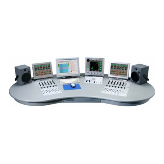
OnAir 3000 Digital Mixing Console Desk Surface The desk surface may consist of some of or all the following elements: • 3- or 6-fader modules with LC Display • 6-fader modules with OLED Display, with optional motor faders (V3.0) • Fader assign module •... -
Page 43: System Wiring Onair 3000, Fixed-Frame Version
The master level meters are part of the on-air screen and not foresee n as a standard module. External meters may be integrated via D21m interface cards; for more information on this subject, please consult the Studer Systems department. All keys can be freely configured and assigned. The large keys have trans- Key Labels: parent caps that allow inserting individual labels. -
Page 44: Fader Module, Led Version
OnAir 3000 Digital Mixing Console Fader Module, LED Version The LED fader module contains three or six fader strips (only two of them shown in the illustration on the left). Up to eight fader modules can be com- bined, giving the maximum configuration for a 48-channel desk. - Page 45 OnAir 3000 Digital Mixing Console When pressing the Select key, the channel page is displayed on the main screen module and shows the last active menu. There, the user can adjust parameters for this channel or select a different page – either by the touch fields and/or...
- Page 46 OnAir 3000 Digital Mixing Console Overload Indication, Analog Inputs: As soon as one sample at an analog input reaches full scale, the overload indicator is on for approx. 300 ms (the idea is that the probability of an A/D converter reaching full scale without clipping is close to zero. Any full-scale levels within the path are considered to be overloads).
-
Page 47: Fader Module, Oled Version
OnAir 3000 Digital Mixing Console Fader Module, OLED Version The fader module with the OLED (organic LED) display contains six fader strips (only one of them shown in the illustration on the left). Up to eight fader modules can be combined, giving the maximum configuration for a 48-chan-... - Page 48 OnAir 3000 Digital Mixing Console The REC function is used to assign the channel signal directly to the record bus, regardless of the fader position, the ON key, and the bus assignment. If active, the key is lit in red.
- Page 49 OnAir 3000 Digital Mixing Console The second bar graph meter in each channel’s OLED display is used for gain reduction indication. It is activated if the channel’s compressor/limiter is active; it can also be configured to be active in De-Esser mode.
-
Page 50: Fader Assign Module
• Tape machine remote control (STOP, PLAY, REC, <<, >>) • Door control • Ring tone, etc. Channel Screen The OnAir 3000 features optional 12” color channel touch screens for “Touch’n’Action” operation. The channel screens are subdivided in 6 rows above each fader strip of the fader module and include symbols for the most important channel settings. -
Page 51: Rotary Module
OnAir 3000 Digital Mixing Console Rotary Module The rotary module consists of six columns with four rotary encoders each (two of them shown in the illustration on the left). Each rotary has an LED ring and two keys. To each row of rotaries a function can be assigned with the rotary assign module described below. -
Page 52: Monitoring / Talkback Module
OnAir 3000 Digital Mixing Console Monitoring / Talkback Module The monitoring and TB module contains the CR loudspeaker controls, the DJ headphone CONTROL ROOM RED LIGHT controls, controls for the built-in PFL/TB/ AUX 1 N–X 1 N–X 5 ON AIR... -
Page 53: Operation
In addition to these hardware and GUI elements on the desk, the OnAir 3000 is also operable by any PC or laptop computer where the OnAir 3000 user GUI is emulated. All hardware... -
Page 54: Channel Screen(S)
OnAir 3000 Digital Mixing Console On the rear side of the main screen unit a USB socket is provided for con- USB Keyboard Operation necting a USB computer keyboard. In this way, some extended functions are available, such as expanding/collapsing items in the configuration menu tree using the →... - Page 55 OnAir 3000 Digital Mixing Console Each channel has its own, vertically oriented channel field, the look of which depends on the input type (mono/stereo/mic/line) routed to this channel: Input DeEs (De-Esser) (not displayed in Surround Pan mode) EQ (Equalizer) DYN (Dynamics)
- Page 56 OnAir 3000 Digital Mixing Console Parameters can be entered or modified there. The field displays the on/off status of the individual parts of the dynamics section: L = limiter, C = com- pressor, E = expander, G = gate. A part is active if the symbol is marked green.
-
Page 57: Main Screen
Red Light Indicators with the red light indicators on the monitoring/talkback module. An on-air condition is indicated by changing the color of the “Frisbee” symbol next to the OnAir 3000 label from blue to red. Operation 5-5 Date printed: 31.10.08... -
Page 58: Color Code
The three indicator fields (CAB, CMS, Router) show the current status of Interface Indicators the optional interfaces to the CAB (computer assisted broadcast) system such as a Studer DigiMedia playout system, to the Call Management System, and to an external router control system. Each of them indicates three different statuses: Grayed out –... -
Page 59: Channel Page
OnAir 3000 Digital Mixing Console 5.3.3 Channel Page There are three ways to open the CHAN page and to automatically select the corresponding channel: Touching the Chan field in the main menu, pressing the SEL key in the channel strip, or (the most direct way) touching the cor- responding field in the channel screen. - Page 60 OnAir 3000 Digital Mixing Console Inverts the audio signal for microphone and mono inputs; inverts the left Phase channel signal for stereo inputs, except in the RR case (see below) – then of course it makes sense to invert the right channel signal. The Phase button is highlighted whenever phase inversion is active.
- Page 61 OnAir 3000 Digital Mixing Console Functions for Mono Inputs Mono inputs have the same functionality as the stereo inputs, but without a stereo mode selector, as shown above. Functions for Microphone Inputs Enables/disables the phantom power for the corresponding mic input; the +48 V button is highlighted when enabled.
- Page 62 OnAir 3000 Digital Mixing Console The microphone input gain can be set in a range of –11 to +75 dB. If gain is Gain set to 0 dB, an input signal with +15 dBu corresponds to 0 dB (i.e., the same level as on an analog line input set to 15 dBu).
- Page 63 OnAir 3000 Digital Mixing Console On the other systems within the network, the Mic Control Access button turns to red and displays information on the system currently having access: If access is requested by a system different from the one currently having access, it displays a user warning: After confirmation with “Yes”, access is taken over.
- Page 64 OnAir 3000 Digital Mixing Console A 5.1 input channel has its own input routing setup accessible from the CHAN Functions for 5.1-Channel Inputs - Input page, where every configured physical input can be routed to any of the 5+1 individual channels. Each of these has its own ±18 dB Cal control, and there is an additional Master calibration control common for all chan- nels.
- Page 65 OnAir 3000 Digital Mixing Console Test Generator Functions For test purposes, the OnAir 3000 features an internal test signal generator available for every channel. While the generator is active, the normal chan- nel buttons in the left part of the page are disabled and displayed in gray. The test generator may only be activated by users having the appropriate access rights configured by the system administrator.
-
Page 66: Channel) De-Esser Page
OnAir 3000 Digital Mixing Console 5.3.3.2 (Channel) De-Esser Page Each channel has an integrated de-esser. This is a dynamically controlled filter, normally used to reduce the “s” components of a microphone signal. The filter range is placed over the signal’s “s” frequency components; if an “s”... -
Page 67: Channel) Equalizer Page
OnAir 3000 Digital Mixing Console 5.3.3.3 (Channel) Equalizer Page Each channel has a parametric four-band equalizer. If the user has no access permission to the EQ parameters, the CHAN - EQ page is not displayed. The red graph represents the EQ’s current frequency response curve, cumu- Graph lated from all filters. -
Page 68: Channel) Dynamics Page
OnAir 3000 Digital Mixing Console 5.3.3.4 (Channel) Dynamics Page Each channel has an internal dynamics processor consisting of a limiter, a compressor, an expander, and a gate section. The dB readings automati- cally consider the selected amount of headroom (i.e., 0 dB indication = 0 dB –... - Page 69 OnAir 3000 Digital Mixing Console Touching one of these edit buttons selects one of the four sections (limiter, LIM, COMP, EXP, GATE compressor, expander, gate) of the dynamics processor for adjustment. The corresponding parameter values appear in the fields above the rotary encoders and can be adjusted.
-
Page 70: Channel) Subgroup Dynamics (Optional)
OnAir 3000 Digital Mixing Console 5.3.3.5 (Channel) Subgroup Dynamics (optional) If the “Subgroups, HP/LP, Ducking” option is installed, there is a particular page available for the subgroups, consisting of a compressor and a ducker. Either compressor or ducker may be selected for each subgroup. - Page 71 OnAir 3000 Digital Mixing Console The subgroup compressor has the same controls as the regular channel com- COMP: pressor, refer to chapter 5.3.3.4. Operation 5-19 Date printed: 31.10.08 SW V3.0...
-
Page 72: Channel) Aux Page
OnAir 3000 Digital Mixing Console 5.3.3.6 (Channel) AUX Page This page contains the controls for the AUX 1...4 auxiliary sends . On/off control for the individual AUX sends; highlighted if on. These buttons allow selection whether the signal for the AUX send is tapped PF / AF before (PF, “pre-fader”) or after (AF) the fader. -
Page 73: Channel) N-X Page
OnAir 3000 Digital Mixing Console 5.3.3.7 (Channel) N–X Page This is an indication on which main output assignment the channel’s contribu- N–X Mode tion to the N–X bus depends (PRG A, PRG B, REC, 5.1 A, or 5.1 B), or whether the bus is used as AUX bus (AF or PF);... - Page 74 OnAir 3000 Digital Mixing Console Indicates the function currently configured to the “Joker” key on the channel Joker strip. For configuration refer to chapter 6.5.1. Activates pre-fader listening for this channel. This button is visible only if an insert from the inserts pool is assigned to this Insert channel.
-
Page 75: Channel) 5.1 Pan Page (Optional)
OnAir 3000 Digital Mixing Console 5.3.3.9 (Channel) 5.1 PAN Page (optional) With SW V2.2 and up, the 5.1 channel surround option is available. It features up to twelve 5.1 channels usable simultaneously (depending on DSP configu- ration), two 5.1 master buses, and two independent 5.1-channel monitoring sections (CR, Studio 1) per core. - Page 76 OnAir 3000 Digital Mixing Console Output Mode MONO Source STEREO Source Center Level Center Level The corresponding channel bullets (L, R, C, LS, RS) change their color from gray to yellow if the mono or stereo source contributes to this channel. The contribution level is displayed next to each active bullet in dB relative to the source’s signal.
- Page 77 OnAir 3000 Digital Mixing Console In case of a stereo (S) source, the level of the center channel (i.e., a mono mix Center Level of the left/right stereo channels) is adjustable from – (i.e. mute) to +12 dB with the rotary encoder below this field.
-
Page 78: Sum Page
OnAir 3000 Digital Mixing Console 5.3.4 Sum Page When touching Sum, the last Master, 5.1, AUX, N–X or Subgr page opens for parameter adjustment. 5.3.4.1 (Sum) Master Page This page opens when selecting it from the Sum page. It allows parameter adjustments for the three main master buses PRG A, PRG B, and Record. -
Page 79: Sum) 5.1 Page (Optional)
OnAir 3000 Digital Mixing Console 5.3.4.2 (Sum) 5.1 Page (optional) This page opens only if the 5.1-channel option is installed, either when se- lecting it from the Sum page, or by pressing the SEL key on a fader strip that has been configured as 5.1-channel master. -
Page 80: Sum) Aux Page
OnAir 3000 Digital Mixing Console 5.3.4.3 (Sum) AUX Page This page allows parameter adjustments for the four AUX master buses. The audio format (mono or stereo) of each AUX master bus can be set to mono Mono / Stereo or stereo when touching these buttons; the current selection is highlighted. -
Page 81: (Sum) N-X Pages
OnAir 3000 Digital Mixing Console 5.3.4.4 (Sum) N–X Pages The control elements for the sixteen N–X master buses are distributed on four different pages with identical layout. The audio format of all N–X buses can be set to mono or stereo when touching Mono / Stereo these buttons;... -
Page 82: (Sum) Sub-Group Pages
OnAir 3000 Digital Mixing Console 5.3.4.5 (Sum) Sub-Group Pages The control elements for the eight sub-groups are distributed on two different pages with identical layout. For all sub-groups the audio format can be set to mono or stereo when touch- Mono / Stereo ing these buttons;... -
Page 83: Monitoring Pages
OnAir 3000 Digital Mixing Console 5.3.5 Monitoring Pages Like all hardware elements, the monitoring and talkback controls in the monitoring/TB module (details in chapter 5.5.1) are available in the GUI as well and work completely in parallel. This has several advantages: A function can be controlled from a remote PC, e.g. -
Page 84: (Monitoring) Cr Lsp/St 1 Lsp (Loudspeakers) Pages
OnAir 3000 Digital Mixing Console If active, a signal from a stereo source passes unprocessed to the L and R Stereo speakers. If the monitored source is a 5.1-channel source, the signal is down- mixed to a stereo signal, according to the Downmix / ENC setting. -
Page 85: (Monitoring) Cr/St 1 Hp (Headphones) Pages
OnAir 3000 Digital Mixing Console 5.3.5.3 (Monitoring) CR/ST 1 HP (Headphones) Pages In normal mode, MON is selected, and the CR and studio 1 DJ headphones DJ phone are then used for monitoring the source selected on the MON - CR or MON... -
Page 86: (Monitoring) Cr Cue/St 1 Cue Pages
OnAir 3000 Digital Mixing Console 5.3.5.4 (Monitoring) CR CUE/ST 1 CUE Pages The MPX conferencing features are available only if the MPX option is in- stalled. Selects which buses will be conference members. If an N–X bus is selected, N–X 1...16 all contributors to this bus will be conference members automatically. -
Page 87: (Monitoring) Studio 2/3 Pages
OnAir 3000 Digital Mixing Console 5.3.5.5 (Monitoring) Studio 2/3 Pages The controls of the studio 2/3 pages are operated in parallel to the controls on the talkback boxes in the corresponding studio(s). The source selector buttons can be configured with the desired sources; the Source Selector currently selected source is highlighted. -
Page 88: Monitoring) Tb Sp Page
OnAir 3000 Digital Mixing Console 5.3.5.6 (Monitoring) TB SP Page This page contains a part of the functionality found on the monitoring/TB module and works in parallel with its controls. For details refer to chapter 5.5.3. Buttons to select a talkback destination (or a group of destinations). For details... -
Page 89: Routing Pages
OnAir 3000 Digital Mixing Console 5.3.6 Routing Pages 5.3.6.1 (Routing) Input Page The input routing page allows setting up the mixing console’s input router; the general rule is that each input can be routed to any channel, but to exactly one channel only. -
Page 90: Routing) Output Page
OnAir 3000 Digital Mixing Console A connection may be protected from changes by selecting it and touching the Lock, Unlock Lock button. If locked, the Connect and Clear buttons are blanked, and a padlock symbol is indicated next to the input label. -
Page 91: Routing) Insert Page
OnAir 3000 Digital Mixing Console When touching Connect, a list appears for output type selection. After se- Connect lection from the list, the blue bullet at the crosspoint indicates the selected type: Input DIR Out PP (pre-processing) DIR Out AP (after processing) -
Page 92: Routing) Mic Group Page
OnAir 3000 Digital Mixing Console Touching one of these buttons opens a list of the available insert points to INSERT1...8 select from. The selected insert point is displayed in the field at the right of the INSERTx buttons. To de-assign an insert point, select None from the list. -
Page 93: Routing) Xl Assign Page
OnAir 3000 Digital Mixing Console 5.3.6.5 (Routing) XL Assign Page The XL module allows direct communication to up to twelve outside sources Extended Line (XL) Module: but may be used for different applications as well. This page allows assigning the desired sources to the module’s keys. With SW V3.0 the total number of possible XL modules has been increased to 20. -
Page 94: Routing) Bus Assign Page
OnAir 3000 Digital Mixing Console 5.3.6.6 (Routing) Bus Assign Page The bus assign page gives a kind of “reverse contribution” overview a nd allows routing channels to buses in a matrix style, as opposed to the con- ventional assignment from within the strip channels. It also gives the user a convenient view of the inputs currently assigned to a bus;... -
Page 95: Snapshot Page
OnAir 3000 Digital Mixing Console 5.3.7 Snapshot Page On this page the static (snapshot) automation is handled. For a general descrip- tion of the snapshot handling refer to chapter 5.7. 5.3.7.1 (SNAP) Shot Page The snapshot list in the left part of the page shows all snapshots available for Local Snapshot List the current user. -
Page 96: (Snap) Route Page ("Partial Output Routing")
OnAir 3000 Digital Mixing Console naming the selected entry with the keyboard appearing then. When finished, confirm with Enter. The Delete button is displayed only if an entry has been selected in the Local Delete snapshot list, and if deleting is available for this entry. It allows deleting the selected entry after confirmation. -
Page 97: Snap) Ext Page
(SNAP) EXT Page This page was called (SNAP) Card page in SW versions below 3.0. Since an USB socket has been added, the OnAir 3000 can now handle external USB memory devices as well as CF (Compact Flash) memory cards. -
Page 98: Admin (System Administrator) Page
OnAir 3000 Digital Mixing Console 5.3.8 Admin (System Administrator) Page If the configuration tool application is installed and the User has access rights to the console configuration, the Admin button is displayed. After touching it, the Display, Fader Cal, Firmware, Date/Time, Config, Scrn Cal, and Setup buttons select the respective pages for basic settings and firmware version display. -
Page 99: Admin) Fader Cal Page
OnAir 3000 Digital Mixing Console 5.3.8.2 (Admin) Fader Cal Page First, select the fader module (up to eight possible) to be calibrated by touch- ing the corresponding button. The screen then changes as follows: 0 dB Position (Always required; please note that it is recommended to perform this calibra- tion for all faders) First, move all faders not to be calibrated to their –20 dB position (this posi-... -
Page 100: Admin) Firmware Page
OnAir 3000 Digital Mixing Console FDR Start Trigger Point Please note that it is recommended to perform this calibration for all faders at a time. First, move all faders not to be calibrated to their –20 dB position (this posi- tion is ignored during calibration). -
Page 101: Admin) Date Time Page
OnAir 3000 Digital Mixing Console 5.3.8.4 (Admin) Date Time Page As long as no external time reference signal is selected, the internal clock is used as time reference, the indication is , and Time Sync Reference None the sync indicator in the upper left corner of the clock dial is gray. To set the system date or time, touch the corresponding button. -
Page 102: Admin) Config Page
OnAir 3000 Digital Mixing Console If you need the screen clock to temporarily display a time different from the true time, touch the set Offset button; the offset can be entered with the rotary encoder below the Offset Time field in a ±12 hours range with a resolution of 30 minutes. -
Page 103: Admin) Scrn Cal Page
Calibration mode for channel screens in a system without main screen can Systems Without Main Screen be entered as well. After applying power to the screen, keep the Studer logo touched until the next page apperas and select screen calibration mode. When proceeding, the same care must be applied as described above. -
Page 104: Admin) Setup Page
OnAir 3000 Digital Mixing Console 5.3.8.7 (Admin) Setup Page This function allows switching between two different, customer-specific con- sole configurations (i.e., all parameters setup during console configuration, including the key assignment, user access rights and passwords). A typical application would be a single-desk configuration with 24 channels that can be switched over to an A/B-desk configuration having two times 12 channels. - Page 105 OnAir 3000 Digital Mixing Console After having changed the setup, the following message appears, indicating that the complete system must be rebooted (i.e., switched off and on again): Operation 5-53 Date printed: 31.10.08 SW V3.0...
-
Page 106: Admin) Gen Page
OnAir 3000 Digital Mixing Console 5.3.8.8 (Admin) GEN Page For test purposes, the OnAir 3000 features an internal test signal generator that is activated from the Chan - Input page (see chapter 5.3.3.1) by users having the appropriate access rights configured. While the generator is active, the normal channel buttons in the left part of the page are disabled and displayed in gray. -
Page 107: Admin) Lsp Cal Page
OnAir 3000 Digital Mixing Console 5.3.8.9 (Admin) LSP CAL Page For both control room and studio 1 (CR/ST 1), the individual levels of the (optional) 5.1 monitor system speakers may be calibrated on this page. First, select the channel to be calibrated with the leftmost rotary encoder or by CHAN SEL touching the desired bargraph. -
Page 108: Login Page
OnAir 3000 Digital Mixing Console 5.3.9 Login Page For details of user access rights please refer to chapter 5.10. To login, a user selects his name from the user list with the rotary encoder below the User Name field, followed by touching the Login button. If more than 50 users should be configured in a system, selection from a list is inconvenient;... -
Page 109: Level Meters
6.5.30. the configuration tool; Level Meters The OnAir 3000’s main screen always displays two stereo level meter bar graphs. They feature 130 segments each and configurable characteristics and scale. Above the meters, a horizontal phase correlation bar graph is located. - Page 110 If desired, commercially available external level meters (such as meters by External Meters DK-Audio, RTW, or Studer) may be installed as an option. Since analog VU meters are very popular in some countries, provisions are made to install this kind of meters as well. To do this, external level meter outputs must be provided in the SCore frame.
-
Page 111: Monitoring, Talkback
OnAir 3000 Digital Mixing Console Monitoring, Talkback The following description refers to the monitoring/TB module in the desk. All functions on this module may also be handled from the GUI, refer to chapter 5.3.5. 5.5.1 Control Room Monitoring In the control room, three possibilities are provided for monitoring signals: •... - Page 112 OnAir 3000 Digital Mixing Console If the monitoring source is “Audition”, the CR and Studio1 monitor speaker’s behavior is depending on the configuration: either muted (CUT), dimmed (DIM), or unaffected (Nothing); in case of CUT or DIM, the corresponding key is illuminated.
- Page 113 OnAir 3000 Digital Mixing Console The PFL, talkback return, and MPX master signals are mixed and fed in mono Internal Speaker to the built-in speaker. If the PFL signal is listened on the CR monitor speakers, it is automatically cut on the internal Speaker.
- Page 114 OnAir 3000 Digital Mixing Console Starting with SW V2.2, the OnAir 3000 is available with the optional 5.1 Surround Control Panel: channel surround monitoring. In such a case, the SURROUND CTRL panel is installed adjacent to the standard monitoring panel, as shown below. This...
-
Page 115: Studio Monitoring
OnAir 3000 Digital Mixing Console 5.5.2 Studio Monitoring Studio1 Monitoring/TB Module: CONTROL ROOM RED LIGHT AUX 1 N–X 1 N–X 5 ON AIR TALKBACK AUX 2 N–X 2 N–X 6 ST 1 AUX 1 GRP 1 AUX 3 N–X 3 N–X 7... - Page 116 OnAir 3000 Digital Mixing Console All monitoring/TB modules are available either in Modulo drop-in version for inclusion into studio furniture, fixed-frame version or in table-top housing. Selection of the studio monitoring source can be done from the main screen Studio Source Selection or from the studio TB box.
- Page 117 GPO signal. Two types of general-purpose desktop boxes in the GPIO Boxes: OnAir 3000 design, both with an illuminated key, and one of them with three additional LEDs are available for many different applications, e.g. cough key, control of external devices, etc.
-
Page 118: Talkback
OnAir 3000 Digital Mixing Console 5.5.3 Talkback Momentary/Latching Talkback Keys A short press on one of the talkback keys latches this talkback function, mean- ing that talkback remains active until the same key is pressed a second time. A long press on one of the talkback keys makes this talkback function work in momentary mode, meaning that talkback is automatically canceled upon release of the key. - Page 119 OnAir 3000 Digital Mixing Console SLATE Allows talkback to the three main buses (PRG A, PRG B, REC). In order to prevent talkback from going to these destinations unintentionally, the SLATE key must be pressed together with the PRG A, PRG B, or REC master talkback keys.
-
Page 120: Talkback Groups
OnAir 3000 Digital Mixing Console 5.5.3.1 Talkback Groups Every location (TB from external, from CR, from Studio 1...3) has up to four TB groups available. The operator can talk from one location to several dif- ferent TB destinations at a time by pressing a single TB group key. -
Page 121: Pfl Button
OnAir 3000 Digital Mixing Console The following TB sources are available: TB Sources No. of TB Buses TBFromExtern 4/16 TBFromExtern1...4/1...16 (SW V3.0 and up, depending on config.) 4/16 TBFromCR (exclusive) TBFromStudio1 (simultaneous) TBFromStudio2 (simultaneous) TBFromStudio3 (simultaneous) As only one of the four specified physical inputs can be the source f or TBFromCR at a time, the user has to select one of them. -
Page 122: Mpx Conferencing (Optional)
OnAir 3000 Digital Mixing Console 5.5.4 MPX Conferencing (optional) MPX conferencing is available as an option for SW V2.2 and up. Two MPX conferences may be setup and active at a time (intended for A/B desk mode). All MPX conference settings may be dynamically changed anytime during operation. - Page 123 OnAir 3000 Digital Mixing Console The console operator can listen to the conference by selecting MPX MASTER on the monitoring/talkback module and adjusting the volume with the SP rotary encoder (or on the GUI with the MPX Master Volume control). To talk to the conference members the MPX key in the TALKBACK key field is used.
-
Page 124: Signaling
OnAir 3000 Digital Mixing Console Signaling The OnAir 3000 has full-way red light signaling, which means that the audio path must be open from the microphone to the master output in order that red light indication becomes active. Signaling settings are performed in the configuration. -
Page 125: Snapshots
OnAir 3000 Digital Mixing Console Snapshots There exist different snapshot types with different read and write authoriza- tions, depending on the user currently logged-in. A snapshot consists of one to four files containing audio, input routing, output routing, and/or assignment parameters. -
Page 126: Snapshot File Contents
OnAir 3000 Digital Mixing Console 5.7.2 Snapshot File Contents The initial general snapshot contains the following parameters: Initial Snapshots General • same as an audio snapshot • same as the input routing snapshot • same as the output routing snapshot •... -
Page 127: Snapshot Operation Details
OnAir 3000 Digital Mixing Console 5.7.4 Snapshot Operation Details For general snapshot operation please refer to chapter 5.3.7.1. The available snapshot operations depend on the current selection within the local snapshot list: Selected Item >> << Rename Delete Creates a new global –... -
Page 128: Snapshot/Ext. Memory Device Operation Details
OnAir 3000 Digital Mixing Console 5.7.5 Snapshot/Ext. Memory Device Operation Details For snapshot/external memory device operation refer to chapter 5.3.7.2. The available snapshot operations depend on the current selection within the local snapshot and the card snapshot lists: Selected Item <<... - Page 129 OnAir 3000 Digital Mixing Console A dialog box “Snapshot ‘name’ already exists. Do you really want to overwrite it?” pops up. When answering Yes, all selected parameter files will be overwritten. If a snapshot containing audio, input routing, output routing, and assignment Note: parameters is overwritten by a snapshot only containing e.g.
-
Page 130: Snapshots During Login
OnAir 3000 Digital Mixing Console 5.7.6 Snapshots During Login • On login of any user, this user’s default snapshot is loaded if available • On login or the default user (or logout of any other user, respectively), de default user’s default snapshot is loaded if available. -
Page 131: User Warnings
OnAir 3000 Digital Mixing Console 5.7.8 User Warnings In contrast to the abovementioned local user warnings generated by the user GUI itself, the snapshot extension also generates its own user warnings, as shown in the table below. SNAPSHOT, Snapshot can- SNAPSHOT, Snapshot File ‘my... -
Page 132: Routing
OnAir 3000 Digital Mixing Console Routing The OnAir 3000 has an integrated audio input and output router. The intel- ligent Input Router can be set during operation from the desk or the GUI. The output router can be set from the GUI. -
Page 133: Physical Audio Inputs And Outputs
OnAir 3000 Digital Mixing Console 5.8.1.1 Physical Audio Inputs and Outputs The OnAir 3000 can be individually equipped with different audio I/O cards such as microphone input cards, analog line I/O cards, AES/EBU I/O cards, multi-channel I/O cards, etc. All physical audio inputs are internally handled as mono signals, regardless of their audio interface format (mono, stereo, multi-channel) and can be put together with the logical Inputs. -
Page 134: Logical Audio Outputs
OnAir 3000 Digital Mixing Console The following information affects the routing and is contained in the configu- ration of a logical audio input: • Input label • Format (mono, stereo, or 5.1 channel surround) • Left-channel audio input (physical input) •... -
Page 135: Channel Format
OnAir 3000 Digital Mixing Console 5.8.2 Channel Format The channel format is not fixed as it usually is in a production console, but it automatically follows the format of the routed input source instead. This means that when routing a mono input source to a console channel forces the channel to operate in mono mode, and routing a stereo input source forces the channel to operate in stereo mode. -
Page 136: Routing Operation
OnAir 3000 Digital Mixing Console 5.8.4 Routing Operation Input routing is either done with the channel’s rotary encoder, or in the ROUT Input Routing - Input page on the main screen (see chapter 5.3.6.1). Routing a new source (MIC 2 to channel 7, instead of CD 1). -
Page 137: Hot-Swapping
OnAir 3000 Digital Mixing Console 5.8.5 Hot-Swapping The hot-swapping feature allows 24 hours console operation without an audio interruption, even if the routing is changed and snapshots are loaded. Hot- swapping also works if the source is currently on-air. However, the destination channel must be inactive, otherwise channel protection is active. -
Page 138: I/O Sharing
OnAir 3000 Digital Mixing Console 5.8.6 I/O Sharing The OnAir 3000’s audio I/O sharing allows routing a physical audio input to more than one logical audio input. If a physical audio input has unique resources (such as the microphone gain... - Page 139 OnAir 3000 Digital Mixing Console The OnAir 3000 console allows free assignment of destination IDs (as used Logical Inputs / Destination IDs: by the router control system for identifying a router output) to the logical in- puts to which the router outputs are connected. The destination IDs are used to set crosspoints when the user selects a source in the CHAN - Input page (see below), and when the router control system reports labels.
-
Page 140: Operation
OnAir 3000 Digital Mixing Console 5.8.7.1 Operation Input selection (see chapter 5.3.3.1) has been extended for this purpose; ex- External Line Selection ternal lines (four-wire connections, i.e. logical inputs controlling an N–X) and external inputs (two-wire connections, logical inputs without N–X control) from the central router have been added to the grouping of internal sources (MIC, LINE, AES/EBU, ADAT, etc.) in the input selection dialog. - Page 141 OnAir 3000 Digital Mixing Console In our example, the Codecs button opens a list of all sources provided by the selected router group (codecs in our example) available for selection; it also indicates the current codec status. Locked – codec #1 is in use and locked to facility #1304. It is impossible to Codec Status select, listen mode is disabled as well.
-
Page 142: Interactions
OnAir 3000 Digital Mixing Console A locked line is currently in use and disabled for selecting or listening to it. Locking a Line Lines can be locked only from the router control system in the master control room. A reserved line can only be listened to but not selected, except from the facil- Line Reservation ity the line is reserved for. -
Page 143: Watch And Stopwatches
OnAir 3000 Digital Mixing Console Watch and Stopwatches The OnAir 3000 main screen continuously displays a watch and two stop- watch functions in the left part of the screen. “Watch” refers to the time-of- day in analog and/or digital format and to the date in an abbreviated format. -
Page 144: Time And Date Setting
OnAir 3000 Digital Mixing Console 5.9.1.1 Time and Date Setting The watch is set in the Admin - Date Time page (see chapter 5.3.8.4). The following parameters can be set: • Time and date (only if free-running, i.e. Time Sync Source = None) •... -
Page 145: User Stopwatch
OnAir 3000 Digital Mixing Console 5.9.2 User Stopwatch The user stopwatch is located just below the fader stopwatch. It is controlled by two keys (START and STOP) below the main screen, next to the digits of the user stopwatch display, as illustrated below. -
Page 146: User Access And Management
User Access and Management 5.10.1 Purpose OnAir 3000 consoles are used in different studios with different working practice and different personnel structures. A large part of users in broadcast studios is not technically oriented. They request from a mixing console that it is simple to use, reliable, and free of “unnecessary”... -
Page 147: Users
OnAir 3000 Digital Mixing Console • Core (container ID = 10) • Desk A (container ID = 100) • Desk B (container ID = 150) • Config Tool (i.e., the remote configuration tool) (container ID = 20) A user called “Operator” is logged in on Desk A, while a user called “DJ” is logged in on Desk B. -
Page 148: Policies
OnAir 3000 Digital Mixing Console In case of A/B desk configurations where two desks share the same Core’s resources, the privileges strictly consider the corresponding desk resource. Example: Desk A uses AUX1 and AUX2, and desk B uses AUX3 and AUX4. - Page 149 OnAir 3000 Digital Mixing Console Single Parameters Privileges of Default Policy Page Parameter Groups (not implemented in V2.1) Admin Default ScreenLock Deesser_On/Off DSAutoThreshold DSFreq Chan::DeEs Other Parameters DSThreshold DSAttenuation DSRatio EQ ON EQ_On/Off LF_gain LMF_gain EQ Gain HMF_gain HF_gain LF_frequency...
- Page 150 OnAir 3000 Digital Mixing Console Single Parameters Privileges of Default Policy Page Parameter Groups (not implemented in V2.1) Admin Default ScreenLock Bus_On/Off AUX 1 Aux_Pre/After Bus_Level Chan::AUX Assign Bus_On/Off AUX 4 Aux_Pre/After Bus_Level Bus_On/Off N–X 1 Bus_Level Chan::N–X Assign Bus_On/Off N–X 16...
- Page 151 OnAir 3000 Digital Mixing Console Single Parameters Privileges of Default Policy Page Parameter Groups (not implemented in V2.1) Admin Default ScreenLock Mono EQ_On/Off EQ_LF_gain EQ_LMF_gain EQ_HMF_gain EQ_HF_gain EQ_LF_frequency EQ_LF_Q EQ_LMF_frequency EQ_LMF_Q EQ_HMF_frequency EQ_HMF_Q EQ_HF_frequency EQ_HF_Q Compressor_gain Subgroup 1 Auto_make_up_On/Off Compressor_On/Off...
- Page 152 OnAir 3000 Digital Mixing Console Single Parameters Privileges of Default Policy Page Parameter Groups (not implemented in V2.1) Admin Default ScreenLock Assign All Parameters ROUT::Mic Group Clear All Parameters Input Selector ROUT::XL Assign Create Modify Snapshot Rename; File & NewName...
-
Page 153: Internal Access Handling
OnAir 3000 Digital Mixing Console 5.10.8 Internal Access Handling The extensions providing the interface to the user are responsible for checking the corresponding privileges. 5.10.8.1 User GUI The user GUI extension checks the privileges on two different levels, i.e. for pages and for console parameters. For a user having no access right to a certain page, this page will not open. -
Page 154: Desk
OnAir 3000 Digital Mixing Console 5.10.8.2 Desk The desk extension checks the privileges for the desk keys and rotary encod- ers. Access to them depends of the current privilege flag setting: The corresponding key or rotary encoder on the desk surface allows control- Grant ling its parameter. -
Page 155: Central User Management
OnAir 3000 Digital Mixing Console 5.10.9 Central User Management With SW V2.1, a new function called “Central User Management” has been introduced. It allows central administration of the console users and their privileges in a network of consoles. Configuration of users and privileges is called “user configuration”... -
Page 156: Standalone Systems
OnAir 3000 Digital Mixing Console 5.10.9.2 Standalone Systems Of course, the concept described above also works for a standalone console. However, for a standalone console without central user management the server is not required. The user extension runs locally on the core container, and it can be configured (in the user.xml file) to provide up to 64 users... -
Page 157: External Audio Synchronization
OnAir 3000 Digital Mixing Console 5.11 External Audio Synchronization The synchronization source may be internal or external. For external synchro- nization, the type of available external synchronization signal(s), i.e., the sync source, must be selected in the configuration (see chapter 6.5.24). -
Page 158: Diagnostics
OnAir 3000 Digital Mixing Console 5.12 Diagnostics The concept of the OnAir 3000 diagnostics system consists of three topics: This is the distribution part for the detected errors, warnings and information Error Handling from the diagnostics system. This is the software running in the background and detecting system errors. -
Page 159: Log System
OnAir 3000 Digital Mixing Console 5.12.1.3 Log System Each mixer has its own internal log list that is automatically displayed on the Home page on the main screen if it contains one or more entries. If a system message occurs, the diagnostics software manages the log list which contains one entry for each system message, completed by time and date of occurrence. -
Page 160: Error Messages
OnAir 3000 Digital Mixing Console Each of these system messages is also entered to the Log List. In order to be removed from the Log List, it has to be acknowledged by the user. To prevent the user from being annoyed with lots of warning and error mes- sage dialog boxes, these are generated only where it is impossible to notice function execution failure. -
Page 161: Core Driver
OnAir 3000 Digital Mixing Console 5.12.3.2 Core Driver Error Code Error Type Error Text / Remarks CORE DRIVER, DSP card failure. DSP card in slot ‘1’ missing. 2000 ERROR Appears during power-up or runtime, if the DSP card is missing. -
Page 162: I/O 21
OnAir 3000 Digital Mixing Console 5.12.3.3 I/O 21 Error Code Error Type Error Text / Remarks I/O 21, Rack ‘Int’: Reconfiguration required. 3001 INFO Appears if a new card has been added. I/O 21, The Rack ‘Ext 1’ was reconfigured. Please make sure the Core is rebooted in order to achieve... - Page 163 OnAir 3000 Digital Mixing Console Error Code Error Type Error Text / Remarks GPIO, The GPIO function on pin ‘3’ doesn‘t work properly! Please check the selected arguments. For GPInput functions: Appears if arguments are missing • during activation of a GPInput function in the ConfigGUI •...
-
Page 164: Desk / User Gui / Configuration Tool
OnAir 3000 Digital Mixing Console 5.12.3.4 Desk / User GUI / Configuration Tool Error Code Error Type Error Text / Remarks 4000 WARNING ‘Config’ Extension not available. 4100 WARNING DESK, No communication to ‘Fader’ module at Port ‘43’ on ‘Container100’. -
Page 165: Snapshot Handling
OnAir 3000 Digital Mixing Console 5.12.3.5 Snapshot Handling Error Code Error Type Error Text / Remarks 5000 WARNING SNAPSHOT, Snapshot File ‘myFirstSnap’ not found or invalid! Snapshot not loaded. SNAPSHOT, Snapshot recall incomplete. Audio parameters of channel ‘2’ on ‘Container100’ are pending. -
Page 166: Probel Controller Extension
OnAir 3000 Digital Mixing Console 5.12.3.8 ProBel Controller Extension Error Code Error Type Error Text / Remarks PROBEL Controller, Could not open port COM‘X’. 8200 WARNING Appears during init phase if the specified COM port cannot be opened. This can happen if the CAB extension is running within the same container as the ProBel controller extension. -
Page 167: Time Sync Card
OnAir 3000 Digital Mixing Console 5.12.3.10 Time Sync Card Error Code Error Type Error Text / Remarks TIME SYNC, No communication to Time Sync Card. 9000 WARNING Appears during power-up or runtime if the selected TimeSyncRef is ExtTimeSync and the communication to the Time Sync Card is lost. - Page 168 OnAir 3000 Digital Mixing Console 5-116 Operation SW V3.0 Date printed: 31.10.08...
-
Page 169: Configuration
CONFIGURATION One of the strong points of the OnAir 2500/3000 consoles is their extensive flexibility. Flexibility from the hardware on one side for the OnAir 3000 in particular, but also a huge amount of flexibility on the system integration side. -
Page 170: Auto Config
OnAir 2500/OnAir 3000 Digital Mixing Consoles Auto Config Unless the console is shipped with a specific, customer-defined configuration, the automatic configuration functions may be applied when powering up the console for the first time. Manually configuring all the different parameters can become a quite time-consuming task, so auto configuration is the recom- mended procedure in such a case. -
Page 171: I/O Init
D21m I/O frame, Auto Config is normally not required. The I/O types marked with an * are not supported by stand-alone OnAir 2500 consoles. I/O cards marked with ** are supported by OnAir 3000 only. A basic label is an input label either generated during auto configuration or Basic Label entered manually during configuration. -
Page 172: Talkback Inputs
AutoConfig. The Config extension will by default assign logical inputs to all the strip channels in ascending order. 6.1.1.5 CR and Studio1 Monitoring Outputs (Studio1 supported by OnAir 3000 only) The first 8 signals of the first ADAT I/O card (if available) are mapped to the fixed outputs as follows:... -
Page 173: Logical Outputs
• * Ethersound I/O cards ® • * Aviom A-Net output cards. ® * OnAir 2500: In external I/O frame only. ** OnAir 3000 only. The eight-character labels are generated according to the same rules given in Label chapter 6.1.1.1. 6.1.1.7 Patch Outputs (supported by OnAir 3000 only) Patch outputs are not initialized by auto configuration;... -
Page 174: Input Groups
• ** SDI, containing all logical inputs mapped to SDI I/O cards • ** Dolby E, containing all logical inputs mapped to Dolby E input cards. * OnAir 2500: In external I/O frame only. ** OnAir 3000 only. remain untouched by auto configuration. -
Page 175: Desk Init
OnAir 2500/OnAir 3000 Digital Mixing Consoles 6.1.2 Desk Init Desk Init is not a factory reset function; it is, however, the basic initialization Note: of specific parameters as listed below, according to pre-defined rules. When touching the Desk Init button on the Admin - Config page, the fol- lowing selections are initialized with the specified values: •... -
Page 176: Gpio Init
OnAir 2500/OnAir 3000 Digital Mixing Consoles After Desk Init, the changes have to be saved as initial snapshot by touching the SaveAll button on the Admin - Config page. Labels are initialized by the initial snapshot. The config extension initializes... -
Page 177: Save Start-Up Config
External Media Load/Save For backup purposes or for copying configurations between consoles, the external media slot comes in handy (OnAir 3000: CF card, OnAir 2500: USB socket). If no external media is plugged into the slot, the Load and Save buttons are inactive and displayed in gray. -
Page 178: Configuration Tool
Notes: on consoles not equipped with the corresponding options, but cannot be expanded there. Some of the menu tree items are supported by the OnAir 3000 only and will not be displayed on an OnAir 2500. 6-10 Confi guration SW V3.0... -
Page 179: Navigation And Handling
Some of the menu tree items are supported by the OnAir 3000 only and will not be displayed on an OnAir 2500. Scrolling within the grid is done by touching the... -
Page 180: Config
OnAir 2500/OnAir 3000 Digital Mixing Consoles Config 6.5.1 Logical Inputs For every logical input that shall be routable to an input channel strip, a physi- cal input (or, if required, a master output or, if required and configured, a tie line) has to be defined. - Page 181 OnAir 2500/OnAir 3000 Digital Mixing Consoles alias label “DJ MIC” are loaded to the same channel strip, and also have the same channel settings. An alias label may be renamed in the same way as the input label described before; it may consist of up to eight characters as well.
- Page 182 External CMS Fader With SW V2.1 and later, the console can communicate commands and status messages with the Studer Call Management System via TCP/IP. Selection: - (none) or 1...16. In addition, a Facility ID must be entered in the UserGUI - Settings con-...
-
Page 183: Logical Outputs
OnAir 2500/OnAir 3000 Digital Mixing Consoles In case that all configured sources should have been cleared inadvertently, and the current configuration has not been saved yet, they can be restored by touching the Undo button, as mentioned in chapter 6.4.2. -
Page 184: Fixed Outputs
OnAir 2500/OnAir 3000 Digital Mixing Consoles buses may be assigned to a physical stereo and mono output at a time. In the example above, the PRG output has its stereo format output (labeled ST PRG) on Logical Out 1 and its mono format output (M PRG) on Logical Out 2. -
Page 185: Insert Sends
OnAir 2500/OnAir 3000 Digital Mixing Consoles meters on the main screen. These outputs may be used to connect additional, external bar graph meters, e.g. in a meter bridge, if required. These outputs are defined here. The same applies as is said in chapter 6.5.2... -
Page 186: Insert Returns
OnAir 2500/OnAir 3000 Digital Mixing Consoles 6.5.6 Insert Returns Basic Label / Label The labels are copied from the Insert Sends page (chapter 6.5.5) and cannot be edited here. They are displayed in the output routing page. Source Left / Source Right Source Left and Right define the physical audio inputs used to establish the insert return. -
Page 187: Encoder Sends
OnAir 2500/OnAir 3000 Digital Mixing Consoles 6.5.7 Encoder Sends (supported by OnAir 3000 only) On this page the outputs to an external surround decoder are defined. Proceed according to chapter 6.5.2. 6.5.8 Encoder Returns (supported by OnAir 3000 only) On this page the inputs from an external surround decoder are defined. Proceed... -
Page 188: Patch Inputs
OnAir 2500/OnAir 3000 Digital Mixing Consoles 6.5.9 Patch Inputs (supported by OnAir 3000 only) Basic Label This is the string displayed in the in the output routing page. It may have up to eight characters. It can be defined as described in chapter 6.5.1. -
Page 189: Patch Outputs
OnAir 2500/OnAir 3000 Digital Mixing Consoles 6.5.10 Patch Outputs (supported by OnAir 3000 only) Label This is the string that is displayed in the output routing page. It may have up to eight characters. It can be defined as described in chapter 6.5.1. -
Page 190: Masters
OnAir 2500/OnAir 3000 Digital Mixing Consoles 6.5.11 Masters The parameters for the summing (master) outputs are set here. Not all param- eters are available for all of the masters; the audition output, e.g., only has a label. Label This is the string that is displayed in the routing output page. The label may have up to eight characters. -
Page 191: Extern Pfls
OnAir 2500/OnAir 3000 Digital Mixing Consoles vates PFL and talkback simultaneously), PFL/LOC (for pre-listening e.g. to a CD player parked at a cue point; when releasing the key, the player re-locates to the same cue point), or blank (no function). -
Page 192: Settings
OnAir 2500/OnAir 3000 Digital Mixing Consoles 6.5.14 Settings On this page global parameters valid throughout the whole console are set. Broadcast PFL Two different versions of this function are available. Selections: PFL Cut on channel active, the PFL audio signal of a channel is cut from the PFL bus while the channel is active, but the PFL function remains active “in the... - Page 193 OnAir 2500/OnAir 3000 Digital Mixing Consoles ChannelOn follows FaderOpen If active, this function automatically switches a channel ON while its fader is open. Selections: On or Off. Gen. off for on-air channels If set to On, this function disables the GEN button on the channel pages for all channels currently being on-air.
-
Page 194: System Time
The type of external time reference signal can be selected here from: None, MONITORA (time information according to the Monitora protocol, e.g. from a Studer DigiMedia CAB system), Ext.Time Sync*, or NTP (if the console has access to an internet time server over a network). If None is selected, the console operates on its own, internal real-time clock. -
Page 195: User Functions
OnAir 2500/OnAir 3000 Digital Mixing Consoles 6.5.16 User Functions User Functions can be assigned as arguments for the “UserLED” GPI function and for the “UserKey” GPO function. This page is used to enter labels for up to 20 user functions. When touching one of the label fields, a keyboard pops up;... -
Page 196: Partial Output Routing
OnAir 2500/OnAir 3000 Digital Mixing Consoles 6.5.18 Partial Output Routing Up to 1024 partial output routing presets may be preconfigured in order to be activated either from the Snap - Route page, or by general purpose inputs (GPI) and/or desk keys. These partial output routings can be configured on this page. -
Page 197: Selections
OnAir 2500/OnAir 3000 Digital Mixing Consoles 6.5.19 Selections “Selections” is a special section that allows selection of various I/O, insert, and meter parameters. 6.5.19.1 Inp Grps This page defines the grouping of inputs when touching the Input Selec- tion field, or in the alphanumeric display in the fader strip if the INP (input) function is selected on the fader assign module while the fader strip rotary encoder is touched. -
Page 198: Patch Grps
OnAir 2500/OnAir 3000 Digital Mixing Consoles 6.5.19.2 Patch Grps (supported by OnAir 3000 only) This page defines the assignment of patch inputs to patch groups that are displayed in the ROUT - Output page. In addition, each patch group can be given a label. -
Page 199: Master Ins
OnAir 2500/OnAir 3000 Digital Mixing Consoles 6.5.19.4 Master Ins This page defines the summing buses and groups to which an insert can be assigned. 6.5.19.5 Strip Assign This page defines the presentation of the ROUT - Input page. In the... -
Page 200: Out Routing
OnAir 2500/OnAir 3000 Digital Mixing Consoles 6.5.19.6 Out Routing This page defines the presentation of the ROUT - Output page when touch- ing the Select Group field, and the logical outputs displayed in the rows on the ROUT - Output page. Since the same output label may exist more than once –... -
Page 201: Meter Src
6.5.19.9 Ducking Key Inputs (supported by OnAir 3000 only) This page allows selecting the keying signals for the automatic ducker. Confi guration 6-33 Date printed: 21.01.09... -
Page 202: I/O Sharing (Option)
OnAir 2500/OnAir 3000 Digital Mixing Consoles 6.5.20 I/O Sharing (Option) I/O sharing allows accessing any signal (input, master, PFL, monitoring, etc.) of one system by another one within the same controller network. When con- necting several systems, some additional things must be considered during configuration: •... - Page 203 OnAir 2500/OnAir 3000 Digital Mixing Consoles Processing parameters (such as EQ, filters, dynamics, panorama/balance, Notes: timer start, etc.) of Net inputs are linked to the target system when defining the logical connection; however, they may be individually modified once the connection is established, and saved in snapshots, too.
-
Page 204: Distributed Control
OnAir 2500/OnAir 3000 Digital Mixing Consoles 6.5.20.1 Distributed Control Starting with SW V2.1, the distributed control feature has been introduced for the Fader Start, On Master, Locate, and Ready control functions. This allows using a GP output or input on a Net Producer system as a control output or input for one or several Net Consumer system(s) without additional wiring. -
Page 205: Define A Physical Connection
OnAir 2500/OnAir 3000 Digital Mixing Consoles 6.5.20.2 Define a Physical Connection Using the configuration tool on the target system, select I/O Sharing - Physi- cal Connections and select an input with the Horizontal rotary encoder (HD Link In 7 in the example below). Then define a source for it by first touching the Source field that is, in our case, still empty (indicated by a “-”... - Page 206 OnAir 2500/OnAir 3000 Digital Mixing Consoles The definition must represent the actual physical (hard-wired) connections Note: established by MADI, AES/EBU etc. wiring. Select one of the outputs (System27, Int, Slot 8, AES, Ch. 1) to define the physical connection. It is displayed afterwards in the corresponding Source field, as shown below.
-
Page 207: Define Logical Inputs, Patch Inputs, Ext. Pfls, Or Ext. Monitoring Sources
OnAir 2500/OnAir 3000 Digital Mixing Consoles 6.5.20.3 Define Logical Inputs, Patch Inputs, Ext. PFLs, or Ext. Monitoring Sources Using the configuration tool on the target system, select I/O Sharing - Logical Connections - LogicalInputs (or PatchInputs, ExternPFLs, or Extern- MonSrc) and select a logical input with the Horizontal rotary encoder (Logi- cal In 2 in the example below). - Page 208 OnAir 2500/OnAir 3000 Digital Mixing Consoles As MD 2 is the desired input in our example, touch the System27, MD 2 entry. After that, the CD 2 input label changes to MD 2, as shown below. The MD 2 audio signal is immediately available on the target system now (pro- vided that sufficient physical connections are available;...
-
Page 209: Define Net Inputs
OnAir 2500/OnAir 3000 Digital Mixing Consoles 6.5.20.4 Define Net Inputs In two-step I/O sharing, Net Inputs must be defined in order to make a neigh- boring Net Source available, e.g. on the Star DEMO 5OG system. Start the configuration tool on the target system and select I/O Sharing - Net Inputs. - Page 210 OnAir 2500/OnAir 3000 Digital Mixing Consoles The label of the specified Net Source is copied to the Net Input, and audio will be connected immediately. If there is any problem connecting to the source system, the label indicates an asterisk (*), as shown below.
-
Page 211: Codec Management
OnAir 2500/OnAir 3000 Digital Mixing Consoles 6.5.21 Codec Management 6.5.21.1 Basics Sharing of common codecs, either from independent systems with the I/O sharing option, or from an A/B desk, is called codec management. The concept is explained on a dual, I/O sharing system; the goal is that a codec I/O Sharing connected to system A may also be used on system B. -
Page 212: Configuration
OnAir 2500/OnAir 3000 Digital Mixing Consoles 6.5.21.2 Configuration Configuration details of the I/O sharing option see chapter 6.5.20. System B (Net Consumer) System A (Net Producer) Step 1: N–X N–X NetLI The codec’s input must be mapped to a patch output (PO). The codec’s output must be mapped to a logical input (LI) that is an N–X bus owner. -
Page 213: Operation
OnAir 2500/OnAir 3000 Digital Mixing Consoles Codec Return Activation Specifies the way in which the return line is connected to the patch output when the (net) logical input is assigned to a fader. Available selections: Con- nect Never, Connect If Not In Use, Connect Always. - Page 214 OnAir 2500/OnAir 3000 Digital Mixing Consoles When assigning the (net) logical codec input to a fader strip on the desk Forced 4-Wire Connection surface, the return line is connected to the codec’s patch output immediately, and the key will then be bright. This connection type is automatically established if the Codec Return Activation is set to Connect Always.
-
Page 215: Monitoring
OnAir 2500/OnAir 3000 Digital Mixing Consoles 6.5.22 Monitoring 6.5.22.1 Settings LSP Dim Level Allows setting the control room and studio loudspeaker dim level in a range of 0 to –80 dB in steps of 1 dB. TB Dim Level Allows setting the talkback dim level (level reduction of the program while talkback is active) in a range of 0 to –80 dB in steps of 1 dB. - Page 216 OnAir 2500/OnAir 3000 Digital Mixing Consoles CR/ST1 HP Split: PFL Gain Headphones PFL signal gain setting in split mode. Range: –89.9...+12 dB, or Mute. OnAir 2500: Studio 1 not supported. CR/ST1 PFL to SP SRC Routes the CR or Studio 1 PFL signal to the PFL/TB speaker. Settings: Yes/No.
-
Page 217: Rotary
OnAir 2500/OnAir 3000 Digital Mixing Consoles 6.5.22.2 Rotary Monitoring Rotary Source Selector CR / ST1 The list of sources for the monitor speakers (MON) that can be selected with the SELECT rotary encoder on the CR (control room) and ST1 (studio 1) monitoring/talkback modules is defined here. -
Page 218: Sp Src
OnAir 2500/OnAir 3000 Digital Mixing Consoles 6.5.22.3 SP SRC SP Source Selector CR/ST1 The list of sources for the PFL/TB speaker (SP) that can be selected with the SELECT rotary encoder on the CR (control room) and ST1 (studio 1) monitoring/talkback modules is defined here (for details see chapters 5.5.1... -
Page 219: Signaling
OnAir 2500/OnAir 3000 Digital Mixing Consoles 6.5.23 Signaling 6.5.23.1 Settings OnAir Mode Selects the condition for switching the ON AIR light on: Internal (i.e., when at least one channel fader is open, this channel is ON, assigned to a master output, this master is defined to be OnAir Relevant - see chapter 6.5.11... -
Page 220: Snapshot
OnAir 2500/OnAir 3000 Digital Mixing Consoles 6.5.24 Snapshot 6.5.24.1 Parameters All global and user snapshots may be saved on a central file server. This is a convenient feature whenever a user works on several different consoles; no matter on which console he is currently logged in, he has access to his snapshots. -
Page 221: Talkback
OnAir 2500/OnAir 3000 Digital Mixing Consoles UserSnapshot: Loading Input ChannelOnOff If set to Off, the user snapshots do not contain the channel ON/OFF settings; i.e. when loading a user snapshot, the channel ON/OFF settings remain as they are. If set to On, the channel ON/OFF settings are saved with the user snapshot and become updated when the snapshot is loaded to the console. -
Page 222: Talkback
OnAir 2500/OnAir 3000 Digital Mixing Consoles 6.5.25.2 TalkBack This page defines the physical inputs used as talkback return sources (up to four summed microphones per studio, one external talkback source TB from Extern, and 16 additional external talkback sources TB from Ext 1...16). -
Page 223: Gpio
OnAir 2500/OnAir 3000 Digital Mixing Consoles 6.5.26 GPIO The GPIO (General Purpose Input/Output) interface allows different console functions to be controlled by external control signals, and to generate control signals depending on the current status of different console functions. Assign- ment of functions and control signals to the pins of the I/O connectors as well as the behavior of the input and output signals can be freely configured. - Page 224 OnAir 2500/OnAir 3000 Digital Mixing Consoles Argument 1...3 Depending on the selected function, up to three different parameters may contribute to the internal processing of the input control signal. These can be selected here. For a function and arguments description see the table below.
- Page 225 OnAir 2500/OnAir 3000 Digital Mixing Consoles Example 1, Momentary Mode: Input Input Level Level Input Input 3 2 3 3 2 3 Status Status Pin Attributes Setting Pin Attributes Setting Activate Activate 0 ms 0 ms Time Time positive negative...
- Page 226 OnAir 2500/OnAir 3000 Digital Mixing Consoles Key LED Configuration Example: The OnAir 2500’s F 1...F 5 keys are normally used to control GPOs. If the unit controlled by the GPO sends a feedback signal, the GPI for the F 1...F 5 key LEDs can be configured as follows: 6-58 Confi...
-
Page 227: Gpo
OnAir 2500/OnAir 3000 Digital Mixing Consoles 6.5.26.2 The GP output logic generates an output signal depending on the GP output function, its parameters, and the argument(s). Argument(s) Parameter(s) Output Pin Level GP Output Function GP Output Logic Label The label of the corresponding frame/GPIO card/output pin is displayed here for reference. - Page 228 OnAir 2500/OnAir 3000 Digital Mixing Consoles On power up, Level is initialized according to the input signal. Notes: Time, Polarity, and Triggered Edge must not be changed while the GP output is active. For correct take-over after a modification, it is important to select Activate to On, because it is automatically set to Off when a modification is made.
- Page 229 OnAir 2500/OnAir 3000 Digital Mixing Consoles To make the output follow the “Level” attribute, the “Activate” attribute must Example 1, Activated: be set, and the “Triggered Edge” attribute must be set to “both”. The “Time” attribute is ignored in such a case.
- Page 230 OnAir 2500/OnAir 3000 Digital Mixing Consoles To get a pulse at the output pin, the “Triggered Edge” attribute must be set Example 4, Pulse Output Mode: to either “rising” or “falling”, the “Time” attribute (> 0 ms) defines the pulse duration.
- Page 231 OnAir 2500/OnAir 3000 Digital Mixing Consoles Notes: • TransparentOut Function Active if the value of the specified parameter is different from zero. This function is normally used for factory testing only. However, by entering the address of a parameter (i.e., the device ID number), a particular function may be monitored by a GP output.
-
Page 232: Desk Common
OnAir 2500/OnAir 3000 Digital Mixing Consoles 6.5.27 Desk Common 6.5.27.1 Mon, TB Keys OnAir 3000 This page allows assigning monitoring sources to the CONTROL ROOM / MONITOR (left) and talkback destinations to the TALKBACK (right) key fields of the monitoring/talkback modules in the control room and in the studios. - Page 233 OnAir 2500/OnAir 3000 Digital Mixing Consoles OnAir 3000 Key Nos. ST1...ST3: 9 10 11 12 13 14 15 16 17 18 19 20 OnAir 3000 Key Nos. TB SP: 9 10 11 12 13 14 15 16 Confi guration 6-65 Date printed: 21.01.09...
- Page 234 OnAir 2500/OnAir 3000 Digital Mixing Consoles OnAir 2500 This page allows assigning monitoring sources to the CR MONITOR (right) and talkback destinations to the TALKBACK (left) key fields of the console’s central module. The Rotary parameter stands here for the key (no. 6) in the CR MONITOR field.
- Page 235 OnAir 2500/OnAir 3000 Digital Mixing Consoles OnAir 2500 Key Nos. ST2: 9 10 11 12 13 14 15 16 17 18 19 20 OnAir 2500 Key Nos. TB SP: 9 10 11 12 Confi guration 6-67 Date printed: 21.01.09 SW V3.0...
-
Page 236: Cue Keys
OnAir 2500/OnAir 3000 Digital Mixing Consoles 6.5.27.2 Cue Keys OnAir 3000 This page allows assigning ten selected cue feeds (i.e., any available input, output, or bus) to the CUE button field of the on the GUI MON-CR CUE and MON-ST1 CUE pages (in the control room and in studio 1). - Page 237 OnAir 2500/OnAir 3000 Digital Mixing Consoles OnAir 2500 This page allows assigning ten selected cue feeds (i.e., any available input, output, or bus) to the CUE button field of the on the GUI MON - CR CUE page (in the control room).
-
Page 238: Output Routing Keys
OnAir 2500/OnAir 3000 Digital Mixing Consoles 6.5.27.3 Output Routing Keys This page allows assigning 24 partial output routings to output routing keys 1...24. Which hardware keys this will be on the desk must be defined in the Desk_KeyMapping.xml file. 6.5.27.4... -
Page 239: Probel
OnAir 2500/OnAir 3000 Digital Mixing Consoles 6.5.28 ProBel (supported by OnAir 3000 only) The ProBel extension provides an interface to remotely set or remove audio connections in the output routing of a controlled device. A remote device can send messages through a serial COM port or via TCP/IP, using the “ProBel General Switcher Communication Protocol”. -
Page 240: Routable Sources
OnAir 2500/OnAir 3000 Digital Mixing Consoles 6.5.28.2 Routable Sources CLEAR Sources The top left CLEAR Sources field is colored brighter than the others; it can be used to clear all configured sources. If it is touched, clearing the sources has to be confirmed in a dialog box. -
Page 241: Audio Clock
• Compact SCore: 1.943.954.21 on Audio Clock card • SCore Live: 1.943.928.22 on Bridge card. AES / EBU Clock On/Off status display. Video Clock (supported by OnAir 3000 only) On/Off status display. Confi guration 6-73 Date printed: 21.01.09 SW V3.0... -
Page 242: User (User Management)
OnAir 2500/OnAir 3000 Digital Mixing Consoles 6.5.30 User (User Management) 6.5.30.1 Admin The system administrator (Admin, user no. 1) automatically has access to all features of the console and its configuration; for him, only the Admin policy (no. 1) is valid. No other policy may be assigned to him; however, the Admin policy may be assigned to other users, if required. -
Page 243: Users
OnAir 2500/OnAir 3000 Digital Mixing Consoles 6.5.30.3 Users The Users page is used to enter the names and passwords for users no. 3...20 (or up to 64 if defined in the user.xml file) on a standalone system. For the system administrator (Admin, user no. 1) and the default user (Default, user no. - Page 244 OnAir 2500/OnAir 3000 Digital Mixing Consoles Users – Policies For user access rights management, one or more policies may be assigned to each user. If more than one policy is assigned, this results in a logical OR combination of the policies. For more information on user privileges and...
-
Page 245: Policies, Departments
OnAir 2500/OnAir 3000 Digital Mixing Consoles 6.5.30.4 Policies, Departments Policies A set of eight policies is available per default. Policy no. 1 (“Admin”) grants access to all parameters and is normally assigned to the system administra- tor only; it may, however, be assigned to other users as well, if required. The... - Page 246 OnAir 2500/OnAir 3000 Digital Mixing Consoles Departments The purpose of this page is entering particular names such as “NEWS” for the eight departments available. When touching one of the matrix fields the pop-up keyboard appears for entering the desired name.
-
Page 247: License Manager
OnAir 2500/OnAir 3000 Digital Mixing Consoles 6.5.31 License Manager 6.5.31.1 Information On this page the system ID code is displayed. When adding an option to the system, this code is used together with the option’s license key in order to gen- erate the option ID code that has to be entered for this option (see below). -
Page 248: Desk
OnAir 2500/OnAir 3000 Digital Mixing Consoles 6.5.32 Desk 6.5.32.1 Fader Assign 1 - Group 1 This page is used to assign functions to the fader rotary assign keys. 17 keys on the optional fader assign module(s), see below/left. OnAir 3000 12 ROTARY ASSIGN keys in the central section, see below/right. -
Page 249: Rotary Assign 2 - Group 2
OnAir 2500/OnAir 3000 Digital Mixing Consoles 6.5.32.2 Rotary Assign 2 - Group 2 (supported by OnAir 3000 only) This page is used to assign functions to the 16 rotary assign keys of the OnAir 3000’s optional rotary assign module(s), see below.With these keys the user can then select the functions of the rotary encoders of the optional rotary modules that are usually installed above the fader strips. -
Page 250: Assignable Rotary Functions
OnAir 2500/OnAir 3000 Digital Mixing Consoles 6.5.32.3 Assignable Rotary Functions Fader Module Rotary Module Key2: Key1: Function: released in: Rotary Function: Key1 Function: Key2 Function: 51AssignmentMode V2.2 51AssignmentMode 51Divergence/CenterLevel V2.2 51Divergence/CenterLevel 51FrontRearPan V2.2 51FrontRearPan 51LR_PanBal V2.2 51LR_PanBal Aux1 V1.0 Aux1_Level... - Page 251 OnAir 2500/OnAir 3000 Digital Mixing Consoles Fader Module Rotary Module Key2: Key1: Function: released in: Rotary Function: Key1 Function: Key2 Function: Exp_Threshold V1.0 Exp_Threshold Dyn_On/Off Exp_On/Off Gain/Cal V1.0 MicGain_Cal Gate_Attack V1.0 Gate_Attack_Time Dyn_On/Off Gate_On/Off Gate_Attenuation V1.0 Gate_Attenuation Dyn_On/Off Gate_On/Off Gate_Release V1.0...
-
Page 252: Assignable Desk Key And Led Functions
OnAir 2500/OnAir 3000 Digital Mixing Consoles 6.5.32.4 Assignable Desk Key and LED Functions Function Desk Element Module Type Assignment Selector V1.0 ●/n ● ● ● ● Aux1...4 On/Off V1.0 ● ● ● Aux1...4 Pre/After V1.0 ● ● ● Aux1..4_Master_On/Off V2.1 ●... - Page 253 OnAir 2500/OnAir 3000 Digital Mixing Consoles Function Desk Element Module Type MicKey1...10 V2.0 ● ● MonHPDJMode V1.0 ●/3 ● ● MonHPDJMode_S1 V2.0 ●/3 ● ● MonLsCRCut V1.0 ● ● ● MonLsCRDim V1.0 ● ● ● MonLsCRMono V1.0 ● ● ●...
- Page 254 OnAir 2500/OnAir 3000 Digital Mixing Consoles Function Desk Element Module Type MPX_ST1_Selection V2.2 ● ● ● ● NearfieldPFL_CR V2.0 ● ● NearfieldPFL_ST1 V2.0 ● ● Next V1.0 ● ● ● NextA (instead of Next) V2.0 ● ● ● NextB (instead of Next) V2.0...
- Page 255 OnAir 2500/OnAir 3000 Digital Mixing Consoles Function Desk Element Module Type StopWatch1_Stop V2.1 ● ● StopWatch2 V2.1 ● StopWatch2_Start V2.1 ● ● StopWatch2_Stop V2.1 ● ● StopWatch3 V2.1 ● StopWatch3_Start V2.1 ● ● StopWatch3_Stop V2.1 ● ● StopWatch4 V2.1 ●...
- Page 256 OnAir 2500/OnAir 3000 Digital Mixing Consoles Function Desk Element Module Type UserLedButtonState21...64 V2.1 ● ● ● ● ● XL_Bus_MixLevel V2.1 ● XL_Line1...12_Bus_On/Off V2.1 ● ● XL_Line1...12_InputLabel V2.1 ● XL_Line1...12_TBfromSrc1 V2.1 ● ● The possible Monitoring sources are: Program_A_Master, Program_B_Master, Record_Master, N-X_Master1..16, AUX_Master1..16, CR_PFL, ST1_PFL, ExternMonSource#1..#16, Input#1..#n, Audition, RotaryId (to listen what‘s selected by the Monitoring Source selection Rotary).
-
Page 257: Snapshot Keys
OnAir 2500/OnAir 3000 Digital Mixing Consoles 6.5.32.5 Snapshot Keys By default, the OnAir 2500 desk has six snapshot keys SK1 to SK6 available. OnAir 2500: These are used to recall the six global snapshots SK1 to SK6 contained in the factory configuration. At time of delivery they are identical with the initial snapshot but can be modified by the administrator. -
Page 258: Settings
OnAir 2500/OnAir 3000 Digital Mixing Consoles Last Snapshot Indication via GPO The last recalled global snapshot may also be communicated via GPO; GPO configuration is identical with the GPI configuration given above, except that the Function Type must be LastSnapshot, and there exists no Action item. -
Page 259: User Gui
When touching this field, the keyboard appears for entering a facility ID used for displaying labels imported from a router control system and/or for communication with the Studer Call Management System. Also refer External Router Destination and External CMS Fader in chapter 6.5.1. -
Page 260: Desk Resources
(Supported by OnAir 3000 only) 6.5.33.2 Desk Resources (supported by OnAir 3000 only) This page contains a part of the most important settings for A/B desk con- figuration, such as the number of the first strip channel, of the first AUX bus, of the first N–X bus, etc., and their respective number for this desk;... -
Page 261: B Desk Configuration
Config GUI. Where is the Console Configuration Saved? The configuration of the OnAir 3000 console is saved in different files and in different locations. *.ini files are located on each container. They are text files that may easily *.ini files... - Page 262 OnAir 3000 Digital Mixing Console Until now, there exist only initial.iss and initial.ios files. All initial... files initial... files together form the initial snapshot or startup configuration file. They are located on the Compact Flash card on the SCore container.
-
Page 263: General
OnAir 3000 Digital Mixing Console General If one single desk container is running within a system, this is called Single Desk Mode. As a special case, a Split Desk may be located in the studio. If two desk containers are running at the same time, this is called A/B Desk Mode. -
Page 264: Alias
OnAir 3000 Digital Mixing Console Alias Aliases allow snapshots to be recalled either on different consoles or on both desks of an A/B Desk mode system. Since Aliases are saved within a snapshot, logical inputs are no longer ref- erenced by their IDs (LogInput ID #1...255) but by the means of the Alias instead. -
Page 265: Preparation
OnAir 3000 Digital Mixing Console Preparation The following two Excel forms help to answer all questions to provide the required information for an A/B Desk configuration: • AB DESK Mode IO Config.xls • AB DESK Mode Desk Resources.xls 7.3.1 A/B Desk Mode I/O Configuration This is an example of an AB DESK Mode IO Config.xls Excel... -
Page 266: Resource Definition
OnAir 3000 Digital Mixing Console 7.3.2 Resource Definition The desk resource definition specifies the SCore resources that can be accessed either by the primary or the secondary desk. Here is an example of the AB DESK Mode Desk Resources.xls Excel sheet, containing the required information for configuring the A/B desk... -
Page 267: Initial Settings
OnAir 3000 Digital Mixing Console 7.3.3 Initial Settings To avoid inconsistencies during A/B Desk Mode configuration, it is strongly recommended to perform the following preparations in advance. User GUI: Channel FDR/bus page, input routing page, output routing page • Make sure that all bus assignments are OFF (PGM A, PGM B, REC, AUX, N–X) and the contribution levels are set to “Mute”... -
Page 268: Channel Screen
OnAir 3000 Digital Mixing Console 7.4.2 Channel Screen container.ini Configure the ContainerIDs of the ChannelScreens as follows: • 110... for the primary desk • 160... for the secondary desk The ChannelScreen will also consider the StripChannel/DeskResource Defi- nition (e.g. ChannelScreen with ID #160 indicates the first six StripChannels of the secondary desk). -
Page 269: Logical Outputs
OnAir 3000 Digital Mixing Console 7.4.5 Logical Outputs Config GUI: Config → LogicalOutputs The following parameters have to be configured according to AB DESK Mode IO Config.xls: • Label • Left/Right CoreOut 7.4.6 Selections Config GUI: Config → Selections → …... -
Page 270: Desk Groups
OnAir 3000 Digital Mixing Console 7.4.6.3 Desk Groups Config GUI: Config → Selections → Desk Grps Usually, the primary desk is Desk Group 1, and the secondary desk is Desk Group 2. Only input groups containing LogicalInputs of the primary desk have to be Notes: added to the desk group of the primary desk (Desk Group 1). -
Page 271: Monitoring Source Selector Keys
OnAir 3000 Digital Mixing Console 7.4.7 Monitoring Source Selector Keys Config GUI: Desk Common → Keys The monitoring sources selectable either on the monitoring/talkback module or within the monitoring page of the User GUI are configured here for each location (CR, ST1...3). -
Page 272: Master Labels For The Secondary Desk
SW V3.0 and up also allows connecting several different CAB systems to Monitora over TCP/IP an OnAir 3000 console, provided that a virtual communications tool such as “Serial to Ethernet Connector” from Eltima Software is used for Monitora control over TCP/IP. -
Page 273: Gpio
OnAir 3000 Digital Mixing Console 7.4.13 GPIO Config GUI: GPIO → GPI Config GUI: GPIO → GPO 7.4.13.1 GPInput Functions for A/B Desk Mode These functions have an additional argument in order to configure to which desk the input pin belongs: •... - Page 274 OnAir 3000 Digital Mixing Console 7-14 A/B Desk Configuration SW V3.0 Date printed: 31.10.08...
-
Page 275: Networking
9.2.1 Network Layer & Setup The OnAir 3000 system supports and uses only IP protocols on the network layer. IP addresses are assigned using DHCP. This can be realized with a regular IT server (software), or with manageable switches or routers that implement this feature. -
Page 276: Canonical Names
OnAir 3000 components with IP addresses in different ranges within a routed network will not be able to communicate with each other by definition. If a router is used to route different OnAir 3000 network domains, and if OnAir 3000 components from these OnAir 3000 network domains are required to interact, it is necessary to forward broadcast or multicast packets. -
Page 277: Onair 3000 Component Packet Types
OnAir 3000 network domain and its components. If OnAir 3000 components such as the LogScreen are placed outside the OnAir 3000 network domain, its fixed IP address can be set up as an “access granted” (pass-thru) entry in the IP filter table on the manageable switch. -
Page 278: Firewall
“n” network ports. 9.2.12 Malware The OnAir 3000 network domain must be free of any malware. Even if mal- ware does not affect the OnAir 3000 components, undesired network traffic could be generated and reduce the performance as a consequence. -
Page 279: General Network Design Example
(arrows) that are applied in a manageable network switch. • The first rule – from the IT network to the OnAir 3000 network domain – will exclude any traffic generated by server and workstation (or other equipment). Only the audio editor (having a fixed IP address) is allowed to pass the rule and send packets to the OnAir 3000 network domain. - Page 280 OnAir 3000 Digital Mixing Console Connect this network domain to the IT network using a controllable path (traffic shaping, IP filtering, or even routing), if desired . Set a single DHCP server up for all networks, or even multiple DHCP servers for each network.
-
Page 281: Typical Network Design Examples
IP Addresses 9.4.1 Stand-Alone Solution In all stand-alone network solutions, one or more OnAir 3000 consoles are in the OnAir 3000 network domain without any interaction to another TCP/IP network. By default, UDP broadcast packets are used by the OnAir 3000 subsystems to establish and maintain the DNET communication. -
Page 282: Single-Console Solution With Dhcp
9.4.1.2 Single-Console Solution with DHCP This is the low cost solution for a single OnAir 3000 console, where the switch must be located together with the console in a studio and with no need of network interconnection (I/O sharing, remote assistance, etc.). -
Page 283: Low Cost Solution With Fixed Ip Addresses
Due to the low price and the fan-less switch, this solution is suitable for single consoles as well as for small OnAir 3000 networks with a few consoles. The following shows a single OnAir 3000 console, where each network sub- system (core, desk, channel screens) has a manually defined, fixed IP address. -
Page 284: Integrated Solution
In order to reach a slight separation of the IT from the OnAir 3000 traffic, a single switch should be used to connect the OnAir 3000 consoles to the IT network. -
Page 285: Routed Solution
The switches and routers of the network must support IGMP V3 (e.g. Cisco Catalyst 2950-24). The routed solution provides the same functionality as the integrated solu- tion. The only difference is that the traffic between the OnAir 3000 and the IT network can be controlled by the router. IT Network... -
Page 286: Requirement Summary
SMB (all Windows server do so). It should be also be possible to have a Linux/Unix server with Samba, but this is not tested! The OnAir 3000 system has to know a DNS server for resolving the name of the NTP server. - Page 287 Studer D21m I/O System Components Product Information (March 2009, 13 Edition)
- Page 288 Prepared and edited by Copyright by Studer Professional Audio GmbH Studer Professional Audio GmbH Printed in Switzerland Technical Documentation Althardstrasse 30 CH-8105 Regensdorf – Switzerland http://www.studer.ch Subject to change Studer is a registered trade mark of Studer Professional Audio GmbH, Regensdorf...
- Page 289 D21m System CONTENTS General .....................................1-1 Utilization for the Purpose Intended ...........................1-1 First Steps ..................................1-1 1.2.1 Unpacking and Inspection ..........................1-1 1.2.2 Installation ................................1-1 1.2.3 Adjustments, Repair, Cleaning ..........................1-2 Introduction ..................................2-1 System Philosophy ..............................2-1 The Frame and its Cards .............................2-3 Hub Frame ...................................2-4 Remote I/O Frame ...............................2-4 Vista Surveyor Software ..............................2-4 Applications ..................................3-1...
- Page 290 D21m System D21m Modules .................................6-1 Available Cards ................................6-1 Analog I/O Cards ................................6-2 6.2.1 Mic/Line In Card ....................A949.0427......6-2 6.2.2 Analog Insert Card ....................A949.0428......6-4 6.2.3 Line In Card ......................A949.0421......6-6 6.2.4 Line Out Card .......................A949.0420......6-8 Digital I/O Cards ...............................6-10 6.3.1 AES/EBU I/O Cards ............. A949.0422, A949.0423, A949.0424......6-10 6.3.2 MADI I/O Cards ............
-
Page 291: General
Check the condition of the equipment for signs of shipping damage. If there should be any complaints you should immediately notify the forwarding agent and your nearest Studer distributor. Please retain the original packing material because it offers the best protection in case your equipment ever needs to be transported. -
Page 292: Adjustments, Repair, Cleaning
Replacing the Supply Unit: changed. In case of failure, the complete power supply unit must be replaced. Please ask your nearest Studer representative. Do not use any liquids to clean the exterior of the unit. A soft, dry cloth or Cleaning: brush will usually do. -
Page 293: Introduction
The D21m I/O system provides very cost-effective inputs and outputs with maximum flexibility while maintaining the well-known Studer sound quality. It is the first Studer I/O system providing full 96 kHz operation. Different I/O modules can be plugged into a frame, providing I/O systems tailor-made to customer needs. - Page 294 Unlike the Studer D19m I/O system, the D21m system is engineered as an Notes: I/O system for use together with a Studer digital console, i.e., using the D21m system as a “standalone” analog-to-digital or digital-to-analog converter only works if MADI I/O is used on the digital side; for more information on this...
-
Page 295: The Frame And Its Cards
D21m System The Frame and its Cards Front View: Rear View: I/O Example: I/O Example: 1 Dual-Slot Card 3 Dual Card Slots 4 Single-Slot Cards 1...2 HD Link Cards RS422 Serial Main and Redundant (Link to DSP Core) I/O Card Power Supply The 3 U frame provides 12 slots for I/O card insertion. -
Page 296: Hub Frame
Remote I/O Frame The frame placed remotely is equipped with a special MADI HD card. This version of the card is not equipped with the Studer proprietary high-density link but with standard MADI optical interfaces. This format allows transfer- ring 64 channels of inputs and outputs between the remote I/O box and the hub frame simultaneously. -
Page 297: Applications
D21m System APPLICATIONS Local I/O Only (Located Close to Core) I/O Frame (One or Multiple) Studer Proprietary HD Link (max. Distance 10 m) SCore & I/O Frame One I/O Box within Long Distance Remote I/O frame with Different Types of I/O Cards... -
Page 298: Multiple I/O Boxes, Long Distance
Information and Mic Control Information and Mic Control (and I/O) 4...6 AES/EBU Outputs to Monitoring Frame Studer Proprietary HD Link (max. Distance 10 m) SCore & I/O Frame Both the remote I/O box and the local hub frames are standard D21m frames,... -
Page 299: Multiple Hubs, Multiple I/O Boxes, Long Distance
RS422 from Desk for Surveyor Information and Mic Control Hub 1 (and I/O) 4...6 AES/EBU Outputs to Monitoring Frame Studer Proprietary HD Link (max. Distance 10 m) SCore & I/O Frame Studer Proprietary HD Link (max. Distance 10 m) Hub 2... -
Page 300: Shared I/O
D21m System card in case of operation with the Performa core) in order to provide I/O for monitoring and talkback of the desk. The RS422 link for the second hub may be taken from the Vista desk by using a further RS422 port. The channel count of the MADI link may be set in steps of eight channels using card-internal DIP switches. -
Page 301: System Examples
D21m System SYSTEM EXAMPLES System with Remote and Local I/O Remote I/O Box, equipped w. e.g.: • 44 Mic Inputs Remote • 8 Line Outputs (Returns) I/O Box or e.g.: • 40 Mic Inputs • 8 Line Inputs • 8 Line Outputs (Returns) or e.g.: •... -
Page 302: System With Remote Midi Connection
D21m System System with Remote MIDI Connection I/O Frames with Different Types of I/O Cards Remote I/O Box 1 ..Remote I/O Box 5 ..Remote I/O Boxes MIDI Signal into 0...64 Ch Optical MADI, incl. MIDI "AUX"... -
Page 303: Additional Information
The HD card is redirecting the audio channels from the different I/O cards into the Studer proprietary HD link format (in case of a hub) or MADI (in case of a remote I/O box). In order to design a complete I/O system, it is mandatory to know which channels of the I/O cards end up being redirected to which one of e.g. -
Page 304: Special Case: Microphone/Line Input Card
D21m System Special Case: Microphone/Line Input Card The smallest modularity of channels used up within the MADI and Core link is eight. If an odd number of Mic/Line input cards is used, they should be inserted in pairs, with the last card in an odd slot (no. 1, 3, 5...) This single card will allocate 8 channels but only 4 of them will have audio. -
Page 305: 96 Khz Operation
45...48 (4 Channels) (4 Channels) Please note that the Studer proprietary HD link is providing 96 channels of inputs to and 48 channels of outputs from the Performa core, in both 48 kHz and 96 kHz operation. Additional Info 5-3 Date printed: 31.03.09... -
Page 306: Input/Output Delays
Processing / Compact SCore 48 kHz Block (OnAir 3000) [smpl] [μs] 1104 Processing / SCore Live 48 kHz 96 kHz Block (OnAir 3000, Vista, Route 6000) [smpl] [μs] [smpl] [μs] Processing / Performa Core 48 kHz 96 kHz Block (Vista) [smpl] [μs]... -
Page 307: Additional Sfc Delay
D21m System 5.5.1 Additional SFC Delay Enabled input and output SFCs each cause an additional delay (D) depending on the input and output sampling rates (f and f S_IN S_OUT Input and output delays can be calculated using the following formulas: [1] f >... -
Page 308: Standalone D21M I/O System
D21m stage boxes. One day they can be used on stage, connected to the Studer console, and the next day in the recording studio in order to bring superb audio quality to lower-cost recording equip- ment. - Page 309 D21m System The frame acts as a clock slave and synchronizes to the optical MADI signal. It therefore automatically detects the clock rate of the connected audio device. Supported clock rates are 44.1, 48, 88.2, and 96 kHz. In 44.1 and 48 kHz mode the two MADI interfaces work in parallel. One of them may be used as a digital split output or for redundancy.
-
Page 310: Connection To The Performa Core
RS422 from Desk for I/O Frame Surveyor Information and Mic Control (One or 4...6 AES/EBU Outputs Multiple) to Monitoring Frame Studer Proprietary HD Link (max. Distance 10 m) Performa DSP Core (PE and PE D21m Cards (within long distance) Remote I/O Box... - Page 311 D21m System D21m MODULES Available Cards # of Console # of Console Name Connector Type Width (Slots) Order No. Format Input Channels Output Channels Analog I/O Cards Mic/Line (4 Dir. Outs) D25 f single A949.0427 Mic/Line Input (incl. Dir. Outs) Line D25 f single...
- Page 312 D21m System Analog I/O Cards A949.0427 6.2.1 Mic/Line In Card Four analog microphone/line inputs, electronically balanced, with 24 bit, 44.1/48/88.2/96 kHz delta-sigma A/D converters (mic/line sensitivity, gain setting in 1 dB steps, low-cut fi lter, soft clipping and 48 V phantom power on/ off controlled by console software);...
- Page 313 D21m System RA1...4: Factory Setting (Level Fine-Adjustment) For each channel a yellow LED indicates if the pantom supply is on. PHANTOM 1...4 LEDs: For each channel a green LED indicates if input signal is present; its bright- SIGNAL 1...4 ness is a rough indication of the signal level. Please note that the input level trimmer potentiometers are factory-set.
- Page 314 D21m System A949.0428 6.2.2 Analog Insert Card This card is intended for use with a D21m Mic/Line In card and features four electronically balanced analog inserts. The insert sends are always active, return on/off is controlled by the console software (default off). Insert sends and returns on standard 25-pin D-type connector (female).
- Page 315 D21m System § Ch 1 §§ § Ch 2 §§ § Ch 3 §§ § Ch 4 §§ Solder Pads: * = Connect for Return Level –9 dB Important: ** = Connect for Return Level +9 dB Do NOT connect * and ** §...
- Page 316 D21m System A949.0421 6.2.3 Line In Card Eight-channel line input card with 24 bit, 44.1/48/88.2/96 kHz A/D Converter, delta-sigma conversion. Transformer-balanced inputs. 96 kHz, 88.2 kHz, 48 kHz, or 44.1 kHz operation. 7...26 dBu input sensitivity. “Signal present” LED indicator. Inputs on standard 25-pin D-type connector (female). Input level (for 0 dB 15/24 dBu (fi...
- Page 317 D21m System Level Ch 1 Level Ch 2 Ch 1 Ch 2 Ch 3 Ch 4 Level Ch 3 Level Ch 4 Level Ch 5 Level Ch 6 Ch 5 Ch 6 Ch 7 Ch 8 Level Ch 7 Level Ch 8 Two positions each: 15 dBu (factory default) or 24 dBu.
- Page 318 D21m System A949.0420 6.2.4 Line Out Card Eight-channel, 24 bit line output card with 24 bit D/A converters with 96 kHz, 88.2 kHz, 48 kHz, or 44.1 kHz operation. Electronically balanced outputs. 7…26 dBu max. output level. Outputs on standard 25-pin D-type connector (female).
- Page 319 D21m System 24 dBu 24 dBu Level Level Ch 1 Ch 2 15 dBu 15 dBu 24 dBu 24 dBu Level Level Ch 3 Ch 4 15 dBu 15 dBu 24 dBu 24 dBu Level Level Ch 5 Ch 6 15 dBu 15 dBu 24 dBu...
- Page 320 AES/EBU input/output card with 16 Ch I/O. With input and output SFCs (A949.0424), with input SFCs only (A949.0423), or without SFCs (A949.0422 – not available for OnAir 3000). Selectable output sampling frequencies: 96 kHz, 48 kHz, 44.1 kHz, or external reference (22...108 kHz).
- Page 321 D21m System 110 Ω Input / output impedance min. 0.2 V Input sensitivity Output level (into 110 Ω) 3.3 V 22...108 kHz SFC range Current consumption (3.3 V) A949.0422: 0.2 A/.0423: 0.4 A/.0424: 0.6 A (5 V) 0.65 A 0...40° C Operating temperature Output Sampling Rate** Output SFC**...
- Page 322 D21m System AES IN/OUT (2 × 25pin D-type, female, UNC 4-40 thread) Connector Pin Assignment: Pin Signal “CH 1...8” Signal “CH 9...16” Pin Signal “CH 1...8” Signal “CH 9...16” CH 7/8 out + CH 15/16 out + 14 CH 7/8 out – CH 15/16 out –...
- Page 323 D21m System A949.0430, A949.0431, A949.0433 6.3.2 MADI I/O Cards The MADI I/O card can establish a 64-channel MADI input and output to the D21m frame, with 44.1/48/88.2/96 kHz operation. Optical inputs and out puts are provided on SC connectors available in multi-mode and single-mode ver- sions, as well as a version with RJ45 connectors for twisted-pair cable and an additional word clock output on a BNC socket.
- Page 324 D21m System MADI I/O Card, Optical Versions A949.0430 / A949.0431 Default Setting: Default Setting: MADI I/O Card, Twisted-Pair Version A949.0433 Default **S1 Setting: 1 2 3 4 5 6 7 8 1 2 3 4 5 6 7 8 Default Setting: Default Setting:...
- Page 325 D21m System ACTIVE IF S1.1 S1.2 MADI MAIN S1.5 Reserved pairs (RJ45) for FS Sync S1.6 transmission S1.3 S1.4 MADI S1.7 (RJ45) S1.8 FS_SYS S4.7 WCLK S4.8 (On versions A949.0430, A949.0431 only) Rotary switch for baud rate selection of the RS422 user interface: Position Setting 115’200 bps (factory default) 57’600 bps...
- Page 326 D21m System DIP switch for MADI setting (on version A949.0433, the switches 4...8 are used differently, as indicated below): Card Versions Switch Setting OFF: AUX IF is used for channel extension at 96 kHz (factory default) ON: AUX IF is used for redundancy at 96 kHz (in 48 kHz mode, AUX IF is used for redundancy regardless of the switch setting) Both OFF: Standard operation (factory default) ALL MADI Cards...
- Page 327 D21m System A949.0425, A949.0429 6.3.3 ADAT I/O Cards Two optical eight-channel ADAT inputs and outputs. 44.1/48/88.2/96 kHz operation; optional long-distance version A949.0429. Optical inputs and out puts are provided on TosLink connectors available in APF (980/1000 µm all-plastic fi bre) and PCF (200/300 µm plastic-clad fi bre) versions. In 96 kHz operation, the number of channels is limited to eight, i.e.
- Page 328 D21m System 16-Ch Mode (Default Setting) 8-Ch Mode These LEDs indicate that valid ADAT signals are available at the respective LEDs: IN CH 1-8, 9-16 inputs. In 96 kHz mode the card handles a total of 8 channels (4 per interface). In Jumper: 8/16 Ch Mode order to avoid different numbers of channels when switching from 96 kHz...
- Page 329 D21m System A949.0426 6.3.4 TDIF I/O Card This card provides two eight-channel TDIF I/O interfaces with 96 kHz, 88.2 kHz, 48 kHz, or 44.1 kHz operation with wordclock sync outputs on BNC connectors. Inputs and outputs are provided on standard 25-pin D-type connectors (female).
- Page 330 D21m System 16-Ch Mode (Default Setting) 8-Ch Mode Connector Pin Assignment, 48 kHz Operation (2 × 25pin D-type, female, UNC 4-40 thread) Pin Signal CH 1...8 Signal CH 9...16 Pin Signal CH 1...8 Signal CH 9...16 CH 1/2 out CH 9/10 out 14 GND CH 3/4 out CH 11/12 out...
- Page 331 D21m System A949.0441 6.3.5 SDI Input Card The HD/SD SDI (serial digital interface) 16-channel de-embedder card is able to de-embed eight or 16 audio channels from SDI-SD as well as from SDI- HD video streams. For the D21m I/O system it acts as an eight-or 16-channel audio input card.
- Page 332 D21m System S1 A...F: ALWAYS OFF Indicates a valid SDI signal at the input. SDI LOCK LEDs: Indicates a valid HD SDI signal at the input. DIP Switches: Switch Setting OFF: 16-channel mode (factory default) ON: 8-channel mode OFF: Group 1/2 used in 8-channel mode (factory default) ON: Group 3/4 used in 8-channel mode OFF: SFC disabled (factory default) ON: SFC enabled...
- Page 333 D21m System A949.0442 6.3.6 SDI I/O Card The HD/SD SDI (serial digital interface) embedder/de-embedder card is able to handle video signals according to the SD as well as the HD standard. It can act as an eight-channel embedder, an eight-channel de-embedder, or as a combination of the two.
- Page 334 D21m System Default Setting: Default Setting: Indicates a valid SDI signal at the input. SDI LOCK LEDs: Indicates a valid HD SDI signal at the input. DIP Switches: Switch Setting OFF: Enable de-embedder (factory default) OFF: Enable embedder (factory default) OFF: SFC bypass (factory default) reserved (must always be OFF) Switch Setting...
- Page 335 For more details on Dolby E please refer to www.dolby.com. ® The D21m Dolby E/Digital card hosts one (A949.0443) or two (A949.0444) The Studer Decoder ® Dolby E decoder modules. Each one is functionally very similar to one Dolby ®...
- Page 336 D21m System Current consumption (3.3 V) 0.2 A (5 V) 0.8 A (A949.0443); 1.3 A (A949.0444) 0...40° C Operating temperature (fitted on A949.0444 ONLY) (must ALWAYS be fitted) Indicate that a valid AES/EBU signal is detected on main input 1/2. M1 / M2 LEDs: Indicate that a valid AES/EBU signal is detected on fallback input 1/2.
- Page 337 D21m System S2.4 S2.4 PCM Latency (Module 1 only) PCM signal is delayed by 1 video frame (factory default) PCM signal is minimally delayed ® Decoding a Dolby E stream always causes a delay of one video frame. In case a regular PCM signal is fed to the card, this can be delayed by one video frame, too.
- Page 338 D21m System S1.4 S1.4 PCM Latency (Module 2 only) PCM signal is delayed by 1 video frame (factory default) PCM signal is minimally delayed Same as S2.4 above, but for module 2. S1.5 S1.5 Module 2 Pulldown Mode Pulldown mode is off (factory default) Pulldown mode is on Same as S2.5 above, but for module 2.
- Page 339 D21m System METADATA OUT (9-pin D-type, female) The Metadata Out socket allows sending the meta data of either module or of both modules at once. If the meta data of either decoder module 1 or 2 is required, plug the short fl...
- Page 340 D21m System A949.0445 ® 6.3.8 CobraNet Card This card allows sending and receiving of up to 32 audio channels to/from a CobraNet . DIP switches on the card allow setting the number of input or ® output channels seen by the console. Default setting is 32 output and no input channels.
- Page 341 D21m System DIP switch for D21m channel count setting: DIP Switch: Number of Channels OFF OFF OFF OFF 0 inputs (factory default) OFF OFF OFF ON 8 inputs OFF OFF ON OFF 16 inputs OFF OFF ON 24 inputs OFF ON OFF OFF 32 inputs NOT ALLOWED OFF OFF OFF OFF 0 outputs...
- Page 342 D21m System A949.0446 ® 6.3.9 Aviom A-Net Card This card allows implementing the head of an Aviom A-Net ® Pro-16 chain. With this standard, 16 mono signals can be fed to an infi nite number of Aviom personal mixers (such as the A-16 II) may be connected in a daisy chain confi...
- Page 343 D21m System Front-Panel Switch: Position Setting OFF: Channels 1 and 2 are mono (factory default) ON: Channels 1 and 2 are a stereo group OFF: Channels 3 and 4 are mono (factory default) ON: Channels 3 and 4 are a stereo group OFF: Channels 5 and 6 are mono (factory default) ON: Channels 5 and 6 are a stereo group OFF: Channels 7 and 8 are mono (factory default)
- Page 344 D21m System (details: www.digigram.com) ® 6.3.10 EtherSound Card The EtherSound ® card allows connecting the D21m I/O System to an Ether- Sound network. Towards the D21m system, it acts similar to a MADI card ® combined with a GPIO card. The number of audio channels used can be confi...
- Page 345 D21m System ES Giga J22: ES 100 Indicate the mode selected with jumper J22. ES-100 / ES-GIGA LEDs: Green: The card is the clock source of the EtherSound network. ® ES CLOCK Red (only in case of a ring network topology): The card was defi ned to be the clock source of the EtherSound ®...
- Page 346 D21m System Non-Audio I/O Cards A949.0435 6.4.1 GPIO Card For general-purpose input/output control signals, this card provides 16 electrically isolated opto-coupler inputs (5...12 VDC) and 16 open-collector outputs. 5 VDC supply pins are available. Inputs and outputs on standard 25-pin D-type connectors (female). Current consumption (5 V) max.
- Page 347 D21m System GPI 1-16 / GPO 1-16 (25pin D-type, female, UNC 4-40 thread) Connector Pin Assignment: Pin Signal “GPI 1-16” Signal “GPO 1-16” Pin Signal “GPI 1-16” Signal “GPO 1-16” GPI 1...4 common GPO 1 14 GPI 11 GPO 14 GPI 1 GPO 2 15 GPI 12...
- Page 348 D21m System A949.0436 6.4.2 GPIO Card with Relay Outputs For general-purpose applications requiring total electrical isolation, this card provides 16 electrically isolated opto-coupler inputs with integrated current sink (5...24 VDC) and 16 electrically isolated outputs using SPST relay con- tacts. 5 VDC supply pins are available. Inputs and outputs on standard 37-pin D-type connectors (female).
- Page 349 D21m System GPI 1-16 / GPO 1-16 (37pin D-type, female, UNC 4-40 thread) Connector Pin Assignment: Pin Signal “GPI 1-16” Signal “GPO 1-16” Pin Signal “GPI 1-16” Signal “GPO 1-16” GPI 1a GPO 1a 20 GPI 1b GPO 1b GPI 2a GPO 2a 21 GPI 2b GPO 2b...
- Page 350 D21m System HD Cards A949.0412 6.5.1 HD Card S The D21m HD card S provides the link to the DSP core systems. Each input and output can handle up to 96 channels in each supported sampling fre- quency (in combination with the Performa core, the number of I/O channels is restricted to 48).
- Page 351 D21m System Default setting Default setting for A949.0412.22 for A949.0412.21 On if a valid signal is available at the input that is locked to the system LOCK LEDs: clock. When using the Performa core, only 48 channels can be transmitted from the DIP switch: core to the D21m system.
- Page 352 D21m System A949.0415 6.5.2 HD RS422 Card The D21m HD RS422 card provides the link to the DSP core systems. Each input and output can handle up to 96 channels in each supported sampling frequency (in combination with the Performa core, the number of I/O chan- nels is restricted to 48).
- Page 353 D21m System Default Setting: Default Setting: On if a valid signal is available at the input that is locked to the system LOCK LEDs: clock. DIP Switches: Switch Setting OFF: Standard mode, 96 channels on each HD IN (factory default) ON: Performa mode, 48 channels on each HD IN OFF: Control data is passed from HD link to RS422 port (factory default);...
- Page 354 D21m System A949.0411, A949.0413, A949.0414 6.5.3 MADI HD Cards Starting with order nos. A949.041124 and A949.041323, resp., the MADI HD Please note: cards have been equipped with the larger dual-slot front panel containing an additional RS422 control connector (left picture). At the same time the MADI HD card with RJ45 connectors (A949.0414) was introduced (right picture).
- Page 355 D21m System Cable length A949.0411, multi-mode fibre <2 km A949.0413, single-mode fibre <15 km (<40 km on request) A949.0414, CAT5e or better, flexible braid <75 m CAT7, solid core <120 m 44.1/48/88.2/96 kHz ±100 ppm Input frequencies Current consumption (3.3 V/5 V) 0.9 A/0.25 A 0...40°...
- Page 356 D21m System DIP switch for MADI setting: Switch Setting OFF: AUX is used as CH33...64 at 88.2 / 96 kHz (factory default) ON: AUX is used as redundant port at 88.2 / 96 kHz OFF: 64 MADI channels (factory default) ON: 56 MADI channels (standard setting for legacy products) OFF OFF MADI1 –...
- Page 357 D21m System MADI MAIN / MADI AUX (8pin RJ45) (on twisted-pair cable version A949.0414 only) Pin Signal MADI RxD + MADI RxD – MADI TxD + WCLK TxD/RxD + Socket View WCLK TxD/RxD – MADI TxD – reserved reserved D21m Modules 6-47 Date printed: 31.03.09...
- Page 358 D21m System Serial/Merger Cards A949.0437 6.6.1 Serial Card It is possible to transmit any RS422 serial signals, such as MIDI or Sony 9- pin (machine control) through a MADI connection without losing any audio channels or microphone control of the remote I/O box. A 9-pin D-type connector can be found on the MADI I/O card (hub frame side) as well as on the serial card of the remote I/O frame.
- Page 359 D21m System Default Setting: S1, DIP switch for RS422 pinout selection: DIP Switch: Setting OFF OFF OFF OFF ON ON RS422 Controller pinout ON OFF OFF OFF OFF RS422 Device pinout (factory default) NO OTHER SETTINGS ALLOWED! RS422 MASTER (9-pin D-type, female) Connector Pin Assignment: Pin RS422 Controller RS422 Device...
- Page 360 A serial connection is made between the Studer product (such as a Vista or OnAir 3000 console) and the MASTER connector of the card. In case of an OnAir 3000 console, the SLAVE connector may be used to connect a second local I/O frame.
- Page 361 D21m System Default Setting: DIP switch for master port selection (versions A949.0438.22 and up): DIP Switch: Setting Depending on application (factory default): – SCore: Master port connected to bridge/host card – D21m stand-alone mode: Master port connected to front-panel MASTER socket Master port forced to front-panel MASTER socket (Vista 5 only) OFF OFF OFF reserved - NO OTHER SETTINGS ALLOWED! RS422 MASTER (9pin D-type, female, UNC 4-40 thread)
- Page 362 Ethernet UTP wiring for connecting the hub frame to the serial card. may be used. An OnAir 3000 desk module connected to the RJ45 connector may be sup- plied by the card (24 V; 20 W max.), can be activated with a DIP switch.
- Page 363 1...5 not used. Default: OFF ON: +24 VDC supply switched to pins 1 and 2 of the RJ45 connector (used for supplying an OnAir 3000 desk module). Default: OFF 7...8 not used. Default: OFF DIP switch for RS422 pinout selection:...
- Page 364 A949.0440 6.6.4 Dual Merger Card This card is used to feed any Studer-internal control signals into the hub I/O frame. A serial connection is made between the Studer product (such as Vista or OnAir 3000 consoles) and the HOST connector of the card. In certain SCore applications the host port is connected internally through the back- plane.
- Page 365 ON: Front control ON: HD card as host not used ON: +24 VDC supply switched to pins 1 and 2 of all RJ45 connectors simultaneously (used for supplying OnAir 3000 desk modules) * ON: HD card connect * ON: HD card connect...
- Page 366 D21m System Power Supply and Miscellaneous A949.0404 (earlier version: A949.0403) 6.7.1 Primary Power Supply The D21m I/O frame may be equipped with either one or, for redundancy purposes, with two primary power supply units. The module used is a primary switching AC/DC converter with an input voltage range of 90...264 VAC/50...60 Hz, automatic power factor correction and a standard IEC mains inlet.
- Page 367 D21m System STATUS (9pin D-type, female, UNC 4-40 thread) on earlier version A949.0403: Pin Signal * Relay NO (‘normally open’) * Relay COMMON Relay NC (‘normally closed’) n.c. Solder/Crimp View n.c. (or Socket View) +24 VDC (650 mA max.) n.c. * Closed if everything is ok A949.0402 6.7.2 LED/PSII PCB...
- Page 368 D21m System A949.0599 6.7.3 Air Deflector/Filter Unit If a D21m I/O frame has a power dissipation of less than 80 W, air deflec- tor/filter units should be used on top of and below the frame. For frames dis- sipating more power, an air deflector/filter unit should be used on top of the frame, combined with a fan unit (see below) at its bottom.
- Page 369 D21m System 6.7.5 Break-Out Boxes For implementing low-granularity standard terminals, a set of passive break- out boxes has been developed. 6.7.5.1 XLR Break-Out Box This box is implemented as a configurable, modular system. The empty box (A949.0580) can be equipped with different options for the left and right part. The picture above shows a break-out box equipped with two options no.
- Page 370 D21m System A949.0588 6.7.5.3 GPIO Break-Out Box For easier wiring of single GPI and/or GPO signals, this break-out box can be used. 16 GPI signals and 12 of the 16 GPO signals of a GPIO card with relay outputs (A949.0436) are wired to single, 4-pin Combicon terminals (see below), providing the relay contacts or opto-coupler inputs, as well as GND and a short circuit-proof 5 VDC supply.
- Page 371 D21m System 6.7.6 Cables Description Length [m] Order no. DB25 and DB37 Cables DB25 m-m 1:1 cable, 8 × shielded 0.45 C089.201161 DB25 m-m 1:1 cable, 8 × shielded C089.201174 DB25 m-m 1:1 cable, 8 × shielded C089.201170 DB37 m-m 1:1 cable C089.201178 DB25 m to XLR Adapter Cables DB25 m to 8 ×...
- Page 372 D21m System Discontinued Components (not available for new systems) A949.0410 6.8.1 HD Card Please note that this card has been replaced by the D21m HD card S and is not available for new systems. The D21m HD card provides the link to the DSP core systems. Each input and output can handle up to 96 channels in each supported sampling frequency (in combination with the Performa core, the number of I/O channels is restricted to 48).
Need help?
Do you have a question about the OnAir 3000 and is the answer not in the manual?
Questions and answers