Table of Contents
Advertisement
Quick Links
Advertisement
Chapters
Table of Contents

Subscribe to Our Youtube Channel
Summary of Contents for LG-Nortel iPECS-50
- Page 1 Administration & Maintenance Manual...
-
Page 2: Revision History
IPECS Release 5 Admin & Maintenance Issue 5.0 Revision History Issue Date Description of Changes 16-Aug-02 Initial release 8-Nov-02 General editing and update to Software version 1.1Bd 29-Aug-03 Final update for iPECS Software release 2. 12-Feb-04 Add Offline Web Admin 19-Apr-04 Update for iPECS S/W Phase 2 18-May-04... - Page 3 IPECS Release 5 Admin & Maintenance Issue 5.0 Issue Date Description of Changes 4.0d5 15-Mar-07 Updated for iPECS S/W Phase 4 (General edits for errata) Keyset Admin PGM 174 – Attr 6 Deleted (Purpose : MISC) PGM 435 – firewall protect default value : from OFF to ON Web Admin PGM 106~109 –...
- Page 4 IPECS Release 5 Admin & Maintenance Issue 5.0 Issue Date Description of Changes Updated for iPECS S/W Phase 5.0 Section 2.3.2.2 partially modified for WTIM Gateway Section 2.3.5.3 & 2.3.5.5 & 2.3.7.2 & 2.3.9.5 partially modified for expanded VSF announcement, was 20 now 70 Section 2.3.18 DECT ATTRIBUTES added Section 3.5.15 DECT Data added Keyset Admin...
-
Page 5: Table Of Contents
IPECS Release 5 Admin & Maintenance Issue 5.0 Table Of Contents 1. Introduction..................1-1 Manual Application................... 1-1 General ....................1-2 Initialization....................1-3 Registration....................1-3 1.4.1 Normal Registration Process ................1-3 1.4.2 Replacement Module Registration ............... 1-4 Virtual LANs .................... 1-5 Program Menu Structure ................. - Page 6 IPECS Release 5 Admin & Maintenance Issue 5.0 2.3.3.15 LSS Label Edit -PGM Code 129- ..................2-38 2.3.4 BOARD (GATEWAY) DATA – PGM CODES 130 to 132 -....... 2-38 2.3.4.1 H323 VoIP Attributes -PGM CODE 130-................2-38 2.3.4.2 T1/E1/PRI Attributes -PGM CODE 131-................2-40 2.3.4.3 Board Base Attributes -PGM CODE 132- ................2-40 2.3.5 CO LINE DATA –...
- Page 7 IPECS Release 5 Admin & Maintenance Issue 5.0 2.3.9.6 Executive/Secretary Table -PGM Code 229- ..............2-114 2.3.9.7 Flexible DID Conversion Table -PGM Code 231- ............2-115 2.3.9.8 System Speed Zone Table -PGM Code 232-..............2-117 2.3.9.9 Auto Ring Mode -PGM Code 233- .................2-118 2.3.9.10 Voice Mail Dialing Table -PGM Code 234-..............2-119 2.3.9.11...
- Page 8 IPECS Release 5 Admin & Maintenance Issue 5.0 3.3.1 Web Admin Data Modification ................3-6 3.3.2 Maintenance & Admin Password................. 3-6 3.3.3 Password Encryption ................... 3-7 WEB ADMIN & MAINTENANCE OVERVIEW .......... 3-8 iPECS WEB ADMINISTRATION............... 3-9 3.5.1 System ID & Numbering Plans ................3-10 3.5.1.1 System ID .........................3-11 3.5.1.2...
- Page 9 IPECS Release 5 Admin & Maintenance Issue 5.0 3.5.5.8 External Control Contacts....................3-89 3.5.5.9 LCD Display Mode......................3-90 3.5.5.10 LED Flashing Rate ......................3-92 3.5.5.11 Music Sources ........................3-95 3.5.5.12 PBX Access Codes ......................3-96 3.5.5.13 Ringing Line Preference Priority..................3-97 3.5.5.14 RS-232 Port Settings......................3-98 3.5.5.15 Serial Port Function Selections ..................3-100 3.5.5.16 Break/Make Ratio ......................3-101...
- Page 10 IPECS Release 5 Admin & Maintenance Issue 5.0 3.5.10.2 Remote Music Address ....................3-182 3.5.10.3 Remote Ext Contact .......................3-183 3.5.10.4 RSGM Alarm Attributes ....................3-184 3.5.11 TNET (Central Control Networking) Data ............3-186 3.5.11.1 Tnet Basic Attributes(PGM 330)..................3-187 3.5.11.2 Tnet CM Attributes (PGM 331) ..................3-188 3.5.11.3 Tnet LM Attributes (PGM 332)..................3-190 3.5.11.4...
- Page 11 IPECS Release 5 Admin & Maintenance Issue 5.0 3.8.4 Station Speed Dial .................... 3-240 3.8.5 Pre-selected Message ..................3-241 3.8.6 Flex Buttons ..................... 3-242 3.8.7 Internal SMS ..................... 3-243 3.8.8 External SMS ....................3-244 3.8.9 Station List Management.................. 3-245 3.8.10 Conference Group .................... 3-246 3.8.11 Station Logout ....................
-
Page 12: Introduction
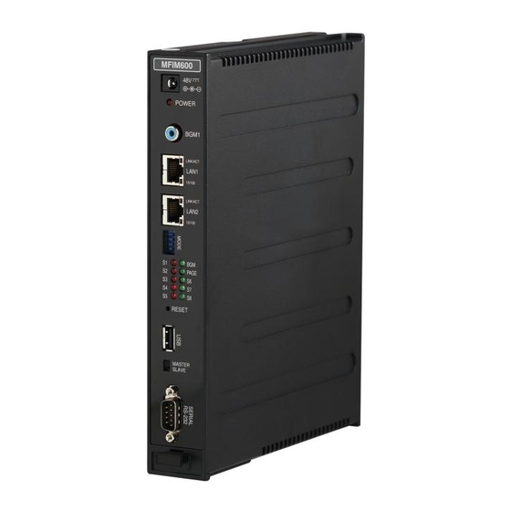
This manual provides detailed information on the database management of the iPECS Series systems. The iPECS Series is available with several versions of the call server configuration including the 50 channel IPECS-50, the 100-channel MFIM100, the 300-channel MFIM300 and the 600-channel MFIM600. -
Page 13: General
VoIP channels*4 Redundancy Note 1 The station and CO Line maximums are not simultaneously; total ports cannot exceed 100 with MFIM100, 50 with IPECS-50, 300 with MFIM300 and 600 with the MFIM600. Note 2 For maximum RSGM connection ports, calculation formula is ports = available system station ports)/2, there must be sufficient VoIP channels to support packet relay for RSGM rtp packets. -
Page 14: Initialization
IPECS Release 5 Admin & Maintenance Issue 5.0 1.3 I NITIALIZATION When power is applied to the MFIM or the MFIM Reset button is pressed, the system will initiate the “Power-up” routine. During the Power-Up routine the system will check the Initialization switch (4th position of the MFIM DIP-switch), refer to the iPECS Description and Installation Manual section 4.4.2. -
Page 15: 1.4.2 Replacement Module Registration
IPECS Release 5 Admin & Maintenance Issue 5.0 iPECS system When power is applied, an Ethernet link is established, and the Registration switch (MFIM DIP- switch position 3) is in the ON position, the MFIM will send a Multi-cast request to unregistered gateway Modules and iPECS terminals for registration. -
Page 16: Virtual Lans
IPECS Release 5 Admin & Maintenance Issue 5.0 1.5 V IRTUAL iPECS devices (modules and terminals) support the IEEE 802.1p/Q standard for Virtual LAN operation. The VLAN priority and ID (tag) are assigned in the Web Admin of each module and terminal. - Page 17 IPECS Release 5 Admin & Maintenance Issue 5.0...
- Page 18 IPECS Release 5 Admin & Maintenance Issue 5.0...
- Page 19 IPECS Release 5 Admin & Maintenance Issue 5.0 Figure 1.6-1 Admin Menu Structure...
-
Page 20: Station Admin Programming
IPECS Release 5 Admin & Maintenance Issue 5.0 TATION DMIN ROGRAMMING 2.1 G ENERAL 2.1.1 LCD & Button Functions While in the , the Liquid Crystal Display (LCD) and Flex button LEDs of an Admin PROGRAM MODE Station are used to guide and indicate status of the feature. The dial-pad is most often used to enter data after selecting a data item using the Flex buttons. -
Page 21: 2.1.3 Required Data Entries
IPECS Release 5 Admin & Maintenance Issue 5.0 2.1.3 Required Data Entries During initialization a default database is established, refer to section 1.3 and Appendix A~D. However, there are several data entries, which MUST be completed to assure proper operation of the system. -
Page 22: Appendix B
IPECS Release 5 Admin & Maintenance Issue 5.0 To change the Country Code: set the MFIM switch 3 and 4 to the On position, follow the procedure below to modify the Country code initialize the MFIM as outlined in the Initialization section. After initialization, reset switches as needed, switch 4 initializes database on reset and switch 3 enables automatic registrations. -
Page 23: Numbering Plans Data – Pgm Codes 102 To 109-
IPECS Release 5 Admin & Maintenance Issue 5.0 Table 2.3.1-2 COUNTRY CODES COUNTRY CODE COUNTRY CODE COUNTRY CODE America Argentina Australia Bahrain Bangladesh Belgium Bolivia Brazil Brunei Burma Cameroon Chile China (Taiwan) Colombia Costa Rica Cyprus Czech Denmark Ecuador Egypt El Salvador Ethiopia Fiji... - Page 24 IPECS Release 5 Admin & Maintenance Issue 5.0 and Terminals such as iPECS SoftPhones, as remote devices, using valuable WAN bandwidth. Assigning the MFIM an IP address from the second segment (“Second Sys IP address”) permits the MFIM to communicate with the devices directly over the LAN. iPECS can be installed behind a NAPT server, if the NAPT server provides fixed address translation and port forwarding to the system.
-
Page 25: Device Ip Address Plan -Pgm Code 103-
IPECS Release 5 Admin & Maintenance Issue 5.0 The system will automatically assign IP addresses to modules AUTOMATIC IP ASSIGN (1:ON/0:OFF): ON and terminals (ON) or, when OFF, IP addresses are assigned manually in 103 Device IP Address Plan. PGM CODE When devices are located on a different private address on 0.0.0.0 SECOND SYS IP ADDRESS... - Page 26 IPECS Release 5 Admin & Maintenance Issue 5.0 For the RSGM, the CO Line port is assigned a CO/IP gateway Sequence Number and the iPECS Phone and SLT port are assigned Terminal Sequence Numbers. The system may assign a default private IP address to each Sequence Number. If desired, this program may be used to modify the assigned IP address for each gateway Module and iPECS Phone.
- Page 27 IPECS Release 5 Admin & Maintenance Issue 5.0 Table 2.3.2.2-1 MODULE & STATION ADDRESS PLAN (PGM 103) DISPLAY FEATURE DEFAULT LCD shows: CO & VoIP Gateway 001-001 :0090A00175A2 VOIP 1 :10 .10 .10 .2 Line 1 Sequence Number, 2 or 3 digits Module IP address MAC Address, 12 digits set sequentially,...
- Page 28 IPECS Release 5 Admin & Maintenance Issue 5.0 DISPLAY FEATURE DEFAULT Use Flex button 1 to set the device’s IP address in 10.10.10.10~254 SET IP ADDRESS IP v4 format. MISC :10.10.10.10 Use Flex button 2 to enter the device’s MAC None SET MAC ADDRESS 001-003 : 00405A017615...
-
Page 29: Co Gateway Sequence Number -Pgm Code 104-
IPECS Release 5 Admin & Maintenance Issue 5.0 DISPLAY FEATURE DEFAULT Use Flex button 3 to enable/disable Direct Send DIRECT SEND (MAC) mode, which employs layer 2 switching to local (1:ON / 0 :OFF): devices. Use Flex button 4 to enable/disable Local Device LOCAL DEVICE (1:ON / 0 :OFF): Mode, which defines the device as on a common... -
Page 30: Flexible Station Numbering Plan -Pgm Code 105-
IPECS Release 5 Admin & Maintenance Issue 5.0 sequence of the gateway modules. Table 2.3.2.3-1 provides the analog CO Line and ISDN Line port numbers based on the physical RJ-21X terminations on the Main Cabinet back plane. PROCEDURE: Press the [PGM] button and dial 104. 001 002 003 004 005 006 001 005 003 006 002 004 Press the Flex button (1~6) for the desired Sequence Number, use the [VOL... -
Page 31: Flexible Numbering Plan Part A To D -Pgm Codes 106 To 109-
Press the [SAVE] button to store the new Numbering Plan data. Table 2.3.2.5-1 FLEXIBLE NUMBERING PLAN PART A (PGM 106) DISPLAY FEATURE DEFAULT iPECS-50 MFIM300 MFIM600 MFIM100 Internal Page Zone access dial codes. 501~510... - Page 32 External Page Zone 1 access dial EXT PAGE ZONE 1 code. ENTER NEW #:545 External Page Zone 2 access dial EXT PAGE ZONE 2 code. Not available in iPECS-50 ENTER NEW #:546 External All Call Page access dial EXT ALL CALL code. ENTER NEW #:548 All Call Page access dial code.
- Page 33 IPECS Release 5 Admin & Maintenance Issue 5.0 DISPLAY FEATURE DEFAULT iPECS-50 MFIM300 MFIM600 MFIM100 Group Call Pick-up dial code. GROUP CALL PICK-UP ENTER NEW #:566 Universal Night Answer dial code. UNIVERSAL NIGHT ANSWER ENTER NEW #:567 Dial code for entering an Account ACCOUNT CODE WITH BIN code.
- Page 34 IPECS Release 5 Admin & Maintenance Issue 5.0 DISPLAY FEATURE DEFAULT iPECS-50 MFIM300 MFIM600 MFIM100 VSF feature access dial code. STA USER VSF FEATURES ENTER NEW #:66 Code for Call Coverage button. CALL COVERAGE RING ENTER NEW #:67 Dial code to activate Directed Call Pick-...
-
Page 35: Station Data – Pgm Codes 110-125-
IPECS Release 5 Admin & Maintenance Issue 5.0 Table 2.3.2.5-4 FLEXIBLE NUMBERING PLAN PART D (PGM 109) DISPLAY FEATURE DEFAULT iPECS-50 MFIM300 MFIM600 MFIM100 Dial code to activate Malicious Call ID MCID REQUEST Request in ISDN Supplementary ENTER NEW #:*0 service. - Page 36 DSS MAP2 : STA ..Consoles (Types 2~4), see Table 2.3.3.1-3 or Table 2.3.3.1-4 for default configurations. Press the [SAVE] button to store the data entries. Table 2.3.3.1-1 STATION TYPE ASSIGNMENT (PGM 110) (MFIM100 & IPECS-50) TYPE DESCRIPTION IP KEYSET DSS MAP 1...
- Page 37 IPECS Release 5 Admin & Maintenance Issue 5.0 Table 2.3.3.1-3 IP CONSOLE BUTTON CONFIGURATION (PGM 110) (MFIM100 & IPECS-50) DEFAULT CONSOLE BUTTON CONFIGURATION MAP 1 * First 12 Buttons: Button 1: ATD Override Button 2: All Call Page Button 3: Call Park 1...
-
Page 38: Station Attributes – I To Iii -Pgm Codes 111-113-
IPECS Release 5 Admin & Maintenance Issue 5.0 2.3.3.2 Station Attributes – I to III -PGM Codes 111-113- Station Attributes define features and functions available to the station. Generally, the entry will turn the feature ON (enable) or OFF (disable). Refer to Table 2.3.3.2-1 to Table 2.3.3.2-3 for a description of the features and the input required. - Page 39 Seq no 100-100 VSF/VMIM GW GW SLOT SEQ: 29 the station are stored. Index to SIP User ID table, 126, for IPECS-50 PGM CODE 100-100 SIP UID TBL (00-70) : 000 the station. Note PGM 126 is accessible by 0- 50 Web only.
- Page 40 IPECS Release 5 Admin & Maintenance Issue 5.0 Button ATTRIBUTE/DISPLAY DESCRIPTION RANGE DEFAULT Each station can choose one of four ring back 0: ring back 100-100 RBTN SRC(0-3) tone sources RING BACK TONE (0) tone Dial-tone 1: Int/Ext 1 MOH 1 2: Ext 2 MOH 2 3: VSF...
- Page 41 IPECS Release 5 Admin & Maintenance Issue 5.0 Button ATTRIBUTE/DISPLAY DESCRIPTION RANGE DEFAULT Select message scroll speed for 7000 series IP 0 ~7 100-110 MSG SCRL SPD phone (Not presently used). (0 - 7) : 3 A station can be assigned as a Hot Desk 0: OFF 100-110 HOT DESK STN (1:ON/0:OFF) : OFF...
- Page 42 IPECS Release 5 Admin & Maintenance Issue 5.0 Table 2.3.3.2-3 STATION ATTRIBUTES III (PGM 113) Button ATTRIBUTE/DISPLAY DESCRIPTION RANGE DEFAULT Enables station access to the System Database. 0:Disable ENABLE 100-110 ADMIN (1:EN/0:DIS) : ENABLE 1:Enable Permits station access to the built-in AA/VM. 0:Disable ENABLE 100-110 VSF ACCESS...
-
Page 43: Station Attributes Iv -Pgm Code 114-
IPECS Release 5 Admin & Maintenance Issue 5.0 Button ATTRIBUTE/DISPLAY DESCRIPTION RANGE DEFAULT If an Agent does not answer an ACD call in the 0: None None 100-110 AUTO ACD-DND ACD No Answer timer, the Agent enters an ([SPD],0-9,*,#): .. #, * Unavailable state with the Reason code entered 1 ~ 9... - Page 44 IPECS Release 5 Admin & Maintenance Issue 5.0 Use the dial-pad to enter a station range (Ex. 100~110). For a single station, 100-110 STATION ATT enter the same number twice. PRESS FLEX_KEY (01-12) Press the desired Flex button, refer to Table 2.3.3.3-1. Refer to Table 2.3.3.3-1 DISPLAY Use the dial-pad to enter desired data for the attribute, refer to Table 2.3.3.3-1.
-
Page 45: Flexible Button Assignment -Pgm Code 115-
IPECS Release 5 Admin & Maintenance Issue 5.0 Button ATTRIBUTE/DISPLAY DESCRIPTION RANGE DEFAULT When an analog device (SLT or FAX) uses an 0: OFF 100-110 3.1 kHz AUDIO ISDN Line in the system, the Information (1:ON/0:OFF ) : OFF 1: ON Element of the ISDN SETUP message must indicate it only has 3.1 KHz audio capabilities. -
Page 46: Appendix C
Press the [SAVE] button to store the Flex button data entry. Table 2.3.3.4-1 FLEX BUTTON TYPE & VALUE CODES (PGM 115) TYPE DESCRIPTION VALUE Remarks iPECS-50 MFIM300 MFIM600 MFIM100 Empty Button Empty (unassigned) button, may be defined by the user. - Page 47 * Note these button definitions cannot be changed. Table 2.3.3.4-3 iPECS DSS CONSOLE DEFAULT CONFIGURATION (PGM 115) (IPECS-50 & MFIM100) DEFAULT CONSOLE BUTTON CONFIGURATION MAP 1 * First 12 Buttons: Button 1: ATD Override Button 2: All Call Page...
-
Page 48: Station Class-Of-Service -Pgm Code 116-
IPECS Release 5 Admin & Maintenance Issue 5.0 2.3.3.5 Station Class-of-Service -PGM Code 116- All stations are assigned a Class-of-Service (COS), which determines the ability of the user to dial certain types of calls, refer to Table 2.3.3.5-1. Separate COS assignments are made for Day, Timed and Night Mode system operation. - Page 49 IPECS Release 5 Admin & Maintenance Issue 5.0 Table 2.3.3.5-2 STATION/CO LINE COS TOLL RESTRICTIONS (PGM 116) CO COS 1 CO COS 2 CO COS 3 CO COS 4 CO COS 5 No Restriction No Restriction No Restriction Only Local Call (LD No Restriction COS 1 code/counter) and...
-
Page 50: Co/Ip Group Access -Pgm Code 117-
Internal Zone will not receive any page announcements including Internal All Call. For the iPECS-50 and MFIM100, ten Internal Page Zones are available and for other MFIMs, there are 35 zones. As a default, all stations except remote stations are assigned to zone 1. -
Page 51: Ptt (Push-To-Talk) Group Access -Pgm Code 119-
IPECS Release 5 Admin & Maintenance Issue 5.0 2.3.3.8 PTT (Push-To-Talk) Group Access -PGM Code 119- Each iPECS Phone is assigned to receive PTT announcements from any combination of the nine PTT groups. Note remote stations and stations not assigned to a group will not receive PTT page announcements including All PTT group page. -
Page 52: Idle Line Selection -Pgm Code 121-
Use the dial-pad to enter the type and value for the desired Idle Line selection, refer to Table 2.3.3.10-1. Press the [SAVE] button to store the data entry. Table 2.3.3.10-1 IDLE LINE SELECTION TYPE & VALUE (PGM 121) TYPE VALUE DESCRIPTION iPECS-50 MFIM300 MFIM600 MFIM100 Flex button Flex button Flex button Flex button, activates Flex Number as if dialed. -
Page 53: Station Ip Attributes -Pgm Code 122-
IPECS Release 5 Admin & Maintenance Issue 5.0 2.3.3.11 Station IP Attributes -PGM Code 122- Stations are allowed access to the systems H.323 VoIP resources based on the Station IP Attributes. Refer to Table 2.3.3.11-1 for a description of the attributes and the inputs available. PROCEDURE: Press the [PGM] button and dial 122. -
Page 54: Linked Station Table -Pgm Code 124-
IPECS Release 5 Admin & Maintenance Issue 5.0 Table 2.3.3.12-1 STATION TIMERS (PGM 123) Button ATTRIBUTE/DISPLAY DESCRIPTION RANGE DEFAULT This timer determines the duration the station 000-600 STA FWD NO ANS TMR sec will ring prior to Ring-No-Answer Forward. (000-600) : 000 seconds This setting affects both manual and Preset Call Forward and overrides the System Ring... - Page 55 IPECS Release 5 Admin & Maintenance Issue 5.0 Table 2.3.3.13-1 LINKED STATION ATTRIBUTES (PGM 124) Button ATTRIBUTE/DISPLAY DESCRIPTION RANGE DEFAULT IP Address of the linked station, not required. SET IP ADDRESS NOT ASSIGNED Set Router IP address associated with linked ROUTER IP ADDRESS station.
-
Page 56: Icm Tenancy Group -Pgm Code 125-
IPECS Release 5 Admin & Maintenance Issue 5.0 2.3.3.14 ICM Tenancy Group -PGM Code 125- Stations can be assigned to an ICM Tenancy group under Station Attributes II 111, PGM CODE button 17. Up to 15 Tenant groups can be defined. Each group is configured to allow or deny placing intercom calls to stations in other groups and an Attendant station can be defined for each group. -
Page 57: Lss Label Edit -Pgm Code 129
IPECS Release 5 Admin & Maintenance Issue 5.0 2.3.3.15 LSS Label Edit -PGM Code 129- The LIP-8012LSS 12 button DSS Console incorporates an LCD used to label the function of each button. The label, which can be up to 12 characters, is assigned in this program. PROCEDURE: Press the [PGM] button and dial 129. - Page 58 Release 5 Admin & Maintenance Issue 5.0 Use the dial pad to enter the VoIP gateway sequence number. For IPECS-50, 001 H323 VOIP BASE ATTR the acceptable range is 001~123. For the MFIM100, the acceptable range is PRESS FLEX KEY (1-14) 001~143.
-
Page 59: T1/E1/Pri Attributes -Pgm Code 131
IPECS Release 5 Admin & Maintenance Issue 5.0 2.3.4.2 T1/E1/PRI Attributes -PGM CODE 131- Each T1/PRI module can be assigned for various attributes of the interface. The T1 interface framing and line coding can be selected and, for the PRI, TE or NT operation and CRC check can be selected. - Page 60 IPECS Release 5 Admin & Maintenance Issue 5.0 point-to-point connection over the managed WAN, including devices on the iPECS LAN. Note that if the device’s Router IP address is not defined, the system will use the Router IP address defined 102.
-
Page 61: Co Line Data - Pgm Codes 140 To 151
Use the dial pad to enter a CO Line range. For a single CO Line, enter the 01-02 SVC TYPE (1-3) same number twice. For the iPECS-50 and MFIM100 the acceptable range is NORMAL CO (1) 01~42, for the MFIM300 the acceptable range is 001~200 and for the MFIM600 the range is 001~400. - Page 62 Table 2.3.5.2-1 CO/IP ATTRIBUTES I (PGM 141) Button ATTRIBUTE/DISPLAY DESCRIPTION RANGE DEFAULT Each CO Line is assigned to a group; IPECS-50 & 01-02 CO/IP GROUP GRP NO (00-21) : 01 grouping should be based on the Line type MFIM100 and COS. 00~21...
- Page 63 IPECS Release 5 Admin & Maintenance Issue 5.0 Table 2.3.5.2-2 CO/IP ATTRIBUTES II (PGM 142) Button ATTRIBUTE/DISPLAY DESCRIPTION RANGE DEFAULT The IP Phone display can indicate the CO 0: OFF 01-02 CO NAME DISPLAY Line/IP channel number or a twelve (12)- (1:ON/0:OFF) : OFF 1: ON character name, if assigned.
- Page 64 Button ATTRIBUTE/DISPLAY DESCRIPTION RANGE DEFAULT When an incoming call on an ISDN Line is IPECS-50 & None 01-02 COLP TABLE INDEX answered, the system will send caller id using INDEX : NOT ASSIGNED MFIM100 the number from the CLIP/COLP Table -PGM 00~10 Code 201- entry defined by this parameter.
- Page 65 IPECS Release 5 Admin & Maintenance Issue 5.0 Button ATTRIBUTE/DISPLAY DESCRIPTION RANGE DEFAULT Permits a user access to ISDN 0: Disable Disable 01- 02 ISDN-SS CD/CR Supplementary Call Deflection or Call Re- (1:EN/0:DIS) : DISABLE 1: Deflect route Service. (Except USA version) 2: Reroute Select one digit remove mode in ISDN Called 0: OFF...
- Page 66 IPECS Release 5 Admin & Maintenance Issue 5.0 Table 2.3.5.2-4 STATION/CO LINE COS TOLL RESTRICTIONS CO COS 1 CO COS 2 CO COS 3 CO COS 4 CO COS 5 No Restriction No Restriction No Restriction Only Local Call (LD No Restriction STA COS 1 Code/Counter) and...
-
Page 67: Co/Ip Ring Assignment -Pgm Codes 144
Use the dial-pad to enter a CO Line range. For a single CO Line, enter the 01-02 PRESS KEY same number twice. For the IPECS-50 and MFIM100 the acceptable range is DAY NIGHT TIMED-R 01~42, for the MFIM300 the acceptable range is 001~200 and for the MFIM600 the range is 001~400.. -
Page 68: Did Service Attributes -Pgm Code 145
Use the dial-pad to enter the DID Line range. For a single DID Line, enter the 01-02 DID ATTRIBUTES same number twice. For the iPECS-50 and MFIM100 the acceptable range is PRESS FLEX_KEY(1–4) 01~42, for the MFIM300 the acceptable range is 001~200 and for the MFIM600 the range is 001~400. -
Page 69: Disa Service Attributes -Pgm Code 146
Use the dial-pad to enter the CO Line range. For a single CO Line, enter the 01-02 DISA ATTRIBUTE same number twice. For the iPECS-50 and MFIM100 the acceptable range is F1:DAY F2:NIGHT F3:TIMED 01~42, for the MFIM300 the acceptable range is 001~200 and for the MFIM600 the range is 001~400. -
Page 70: Co Line Preset Forward Attributes -Pgm Code 147
Use the dial-pad to enter the CO Line range. For a single DID Line, enter the 01-02 CO PRE-FWD same number twice. For the IPECS-50 and MFIM100 the acceptable range is PRESS FLEX_KEY(1–3) 01~42, for the MFIM300 the acceptable range is 001~200 and for the MFIM600 the range is 001~400. -
Page 71: Na Isdn Line Attributes -Pgm Code 150
Use the dial-pad to enter a CO Line range. For a single CO Line, enter the 01-02 COL NA ISDN ATT same number twice. For the IPECS-50 and MFIM100 the acceptable range is PRESS FLEX KEY (1-6) 01~42, for the MFIM300 the acceptable range is 001~200 and for the MFIM600 the range is 001~400. -
Page 72: Isdn Co Line Attributes
Use the dial-pad to enter a CO Line range. For a single CO Line, enter the 01-02 COL ISDN ATT same number twice. For the iPECS-50 and MFIM100 the acceptable range is PRESS FLEX KEY (01-16) 01~42, for the MFIM300 the acceptable range is 001~200 and for the MFIM600 the range is 001~400. - Page 73 IPECS Release 5 Admin & Maintenance Issue 5.0 Button ATTRIBUTE/DISPLAY DESCRIPTION RANGE DEFAULT If the terminal initiates the link monitoring 5~15 001-002 T203 (05 – 15 ) function, it must provide one T203 timer for (05-15) : 10 (sec) (seconds) each logical link supported.
-
Page 74: T1 Line Timers -Pgm Code 152
Use the dial-pad to enter a CO Line range (Ex. 001-002). For a single CO 001-002 COL T1 ATT Line, enter the same number twice. For the iPECS-50 and MFIM100 the PRESS FLEX KEY (01-13) acceptable range is 01~42, for the MFIM300 the acceptable range is 001~200 and for the MFIM600 the range is 001~400. -
Page 75: Dcob Co Attribute -Pgm Code 153
Use the dial-pad to enter a CO Line range (Ex. 001-002). For a single CO 001-002 DCOB CO ATT Line, enter the same number twice. For the iPECS-50 and MFIM100 the PRESS FLEX KEY (1-5) acceptable range is 01~42, for the MFIM300 the acceptable range is 001~200 and for the MFIM600 the range is 001~400. -
Page 76: System Data - Pgm Codes 160 To 182
IPECS Release 5 Admin & Maintenance Issue 5.0 2.3.6 SYSTEM DATA – PGM CODES 160 to 182 - 2.3.6.1 System Attributes I & II -PGM Codes 160 to 161- There are two (2) System Attributes programs to define settings that affect system-wide features and functions. - Page 77 IPECS Release 5 Admin & Maintenance Issue 5.0 Button ATTRIBUTE/DISPLAY DESCRIPTION RANGE DEFAULT The system can be configured to queue 0: OFF ATD CALL QUE AVAILABLE incoming calls to a busy Attendant. (1:ON/0:OFF) : ON 1: ON This field allows Main attendants access to all 0: OFF USE PGM_0 IN ALL ATTD (1 : ON/ 0 : OFF) : OFF...
- Page 78 IPECS Release 5 Admin & Maintenance Issue 5.0 Table 2.3.6.1-2 SYSTEM ATTRIBUTES II (PGM 161) Button ATTRIBUTE/DISPLAY DESCRIPTION RANGE DEFAULT Off-hook ring can be a single tone burst or 0: BURST MUTE OFF-HOOK RING TYPE muted normal ring. (1:MUTE/0:BURST) : MUTE 1: MUTE A warning tone can be sent prior to a page 0: OFF...
- Page 79 IPECS Release 5 Admin & Maintenance Issue 5.0 Button ATTRIBUTE/DISPLAY DESCRIPTION RANGE DEFAULT The Web Admin password can be encrypted 0: OFF WEB PWD ENCRYPT for security using RC-6 block encryption A (1:ON/0:OFF) : OFF 1: ON Java VM must be installed on the user’s PC. System Authorization codes are entered by 0: OFF OLD AUTH CODE USAGE...
-
Page 80: System Password -Pgm Code 162
IPECS Release 5 Admin & Maintenance Issue 5.0 2.3.6.2 System Password -PGM Code 162- Access to the system database and maintenance functions can be protected by passwords up to twelve (12) digits. Three passwords can be defined, User, Admin and Maintenance. Maintenance password has full and unlimited access to the database and maintenance functions of the system. -
Page 81: Alarm Attributes -Pgm Code 163
IPECS Release 5 Admin & Maintenance Issue 5.0 2.3.6.3 Alarm Attributes -PGM Code 163- The system can monitor an external contact. This contact is most often employed as an Alarm indicator or Doorbell. The Alarm attributes define the operation of the external contact. The Alarm Signal sent to assigned stations can be repeating or a single burst, the former is often desired. -
Page 82: Attendant Assignment -Pgm Code 164
Issue 5.0 2.3.6.4 Attendant Assignment -PGM Code 164- A maximum of four (4) Attendants can be assigned with the iPECS-50 and MFIM100 or five (5) with other MFIMs. One is the System Attendant and remaining are the Main Attendants. The System Attendant has higher priority in call handling and system management functions with access to PGM 0. - Page 83 IPECS Release 5 Admin & Maintenance Issue 5.0 Table 2.3.6.5-1 MULTI-CAST RTP/RTCP PORTS (PGM 165) (iPECS-50 & MFIM100) Button ATTRIBUTE/DISPLAY DESCRIPTION RANGE DEFAULT RTP and RTCP ports for internal BGM. 0000-9999 8100 M-CAST RTP BGM INT 8100 (8101) (8101) RTP and RTCP ports for external BGM 1.
- Page 84 IPECS Release 5 Admin & Maintenance Issue 5.0 Button ATTRIBUTE/DISPLAY DESCRIPTION RANGE DEFAULT RTP and RTCP ports for PTT group 1. 0000-9999 8136 M-CAST RTP PTT 1 8136 (8137) (8137) RTP and RTCP ports for PTT group 2. 0000-9999 8138 M-CAST RTP PTT 2 8138 (8139) (8139)
- Page 85 IPECS Release 5 Admin & Maintenance Issue 5.0 Button ATTRIBUTE/DISPLAY DESCRIPTION RANGE DEFAULT RTP and RTCP ports for Internal Page 4. 0000-9999 8112 M-CAST RTP I-PAGE 4 8112 (8113) (8113) RTP and RTCP ports for Internal Page 5. 0000-9999 8114 M-CAST RTP I-PAGE 5 8114 (8115) (8115)
- Page 86 IPECS Release 5 Admin & Maintenance Issue 5.0 Button ATTRIBUTE/DISPLAY DESCRIPTION RANGE DEFAULT RTP and RTCP ports for Internal Page 23. 0000-9999 8150 M-CAST RTP I-PAGE 23 8150 (8151) (8151) RTP and RTCP ports for Internal Page 24. 0000-9999 8152 M-CAST RTP I-PAGE 24 8152 (8153) (8153)
-
Page 87: Disa Cos -Pgm Code 166
IPECS Release 5 Admin & Maintenance Issue 5.0 Button ATTRIBUTE/DISPLAY DESCRIPTION RANGE DEFAULT RTP and RTCP ports for PTT group 2. 0000-9999 8188 M-CAST RTP PTT 2 8148 (8149) (8189) RTP and RTCP ports for PTT group 3. 0000-9999 8190 M-CAST RTP PTT 3 8150 (8151) (8191) -
Page 88: Did/Disa Destination -Pgm Code 167
IPECS Release 5 Admin & Maintenance Issue 5.0 2.3.6.7 DID/DISA Destination -PGM Code 167- When a DID line or DISA user dials an invalid/vacant or busy station number the caller will be sent to the assigned destination. The destination is separately defined for invalid, busy, and no answer conditions and can be defined as the Attendant, busy tone or Station Group. -
Page 89: External Control Contacts -Pgm Code 168
IPECS Release 5 Admin & Maintenance Issue 5.0 2.3.6.8 External Control Contacts -PGM Code 168- The MFIMs include programmable contacts, which can be used to control external devices. Refer to Table 1.1-1 System Capacity Chart for number of available contacts. Each contact is assigned to activate under one of several conditions. - Page 90 IPECS Release 5 Admin & Maintenance Issue 5.0 Table 2.3.6.9-1 LCD DISPLAY MODE (PGM 169) Button DISPLAY DESCRIPTION RANGE DEFAULT Sets the Date display as month/day or 1: MM-DD-YY DDMMYY LCD DATE MODE (1:MMDD/0:DDMM): DUMMY day/month. 0: DD-MM-YY Sets the Time display mode as 12 1: 12 Hour Mode 12 Hour LCD TIME MODE...
-
Page 91: Button Led Flash Rate -Pgm Code 170
IPECS Release 5 Admin & Maintenance Issue 5.0 2.3.6.10 Button LED Flash Rate -PGM Code 170- The LED flash rate for various functions and states can be assigned any one of the system’s 15 signals. The various functions and states are shown in Table 2.3.6.10-1. The 15 flash signals available in the system are shown in Table 2.3.6.10-2. - Page 92 IPECS Release 5 Admin & Maintenance Issue 5.0 Button ATTRIBUTE/DISPLAY DESCRIPTION RANGE DEFAULT CO button supplementary call waiting 00-14 FLASH 240 IPM COL SUPP CW flashing rate. FLASH 240 IPM FLUTTER FLUTTER CO button supplementary hold flashing 00-14 FLASH 480 IPM COL SUPP HOLD rate.
-
Page 93: Music Sources -Pgm Code 171
Music inputs are provided for use as the Background Music and/or Music-On-Hold source inputs. iPECS-50 provides a single input, other MFIMs provide for two (2) music inputs. The first input can be either the internal source or the external BGM1. Note that the BGM1 input on the front panel of the MFIM and the BGM1 input on the rear panel of the MFIM are electrically connected and only one (1) should be used;... -
Page 94: Pbx Access Codes -Pgm Code 172
IPECS Release 5 Admin & Maintenance Issue 5.0 2.3.6.12 PBX Access Codes -PGM Code 172- When the system is used “behind” a PBX/CTX, the system needs to recognize the PBX/CTX Trunk access codes to implement dialing restriction, tone detection sequences and Flash timing. A maximum of four (4) Trunk Access Codes of one (1) or two (2) digits can be entered. -
Page 95: Port Settings -Pgm Code 174
Issue 5.0 2.3.6.14 RS-232 Port Settings -PGM Code 174- The system has RS 232 serial ports located on the MFIM; one on the iPECS-50 and MFIM100 and two on the MFIM300 and MFIM600, refer to the iPECS Description and Installation Manual, Section 4.4.2. -
Page 96: Serial Port Function Selections -Pgm Code 175
The system has RS 232 serial ports located on the MFIM; one RS 232 serial ports located on iPECS-50 and MFIM100, and two (2) on the MFIM300 and MFIM600, Also, the system can employ IP over three (3) TCP channels for the output of various system information. - Page 97 IPECS Release 5 Admin & Maintenance Issue 5.0 Button DISPLAY DESCRIPTION RANGE DEFAULT Defines the serial port or TCP channel used to 1 ~ 5 SERIAL1 CALL INFO (1-5) receive Call Information output. SERIAL1 (1) Defines the serial port or TCP channel used 1 ~ 5 SERIAL1 ON-LINE SMDR (1-5)
-
Page 98: Break/Make Ratio -Pgm Code 176
IPECS Release 5 Admin & Maintenance Issue 5.0 2.3.6.16 Break/Make Ratio -PGM Code 176- For Pulse dial CO Lines, the system supports 10pps and the percent break/make ratios of 67/33 or 60/40. PROCEDURE: Press the [PGM] button and dial 176. BREAK/MAKE RATIO (1:66/33 / 0: 60/40): 60/40 Dial the digit (1 or 2) for the desired Break/Make ratio:... - Page 99 IPECS Release 5 Admin & Maintenance Issue 5.0 Button DISPLAY DESCRIPTION RANGE DEFAULT The system can record all outgoing calls or 1: LD RECORD TYPE only long distance calls. Long distance calls (1 : LD/ 0: ALL) : LD 0: ALL are identified by the LD digit count and LD calls codes assigned in Flex button 4 and 19,...
- Page 100 IPECS Release 5 Admin & Maintenance Issue 5.0 Button DISPLAY DESCRIPTION RANGE DEFAULT Delete SMDR records after sending e-mail. 0: OFF AUTO DELETE MODE (1 : ON/ 0: OFF) : OFF 1: ON For SMDR and COS purposes, five (5) Long Flex button Btn 1: 0 LONG DISTANCE CODE...
-
Page 101: System Date, Time And Daylight Saving Time (Dst) -Pgm Code 178
IPECS Release 5 Admin & Maintenance Issue 5.0 2.3.6.18 System Date, Time and Daylight Saving Time (DST) -PGM Code 178- The system Date, Time and DST feature are established by this entry. The date and time are employed for several features and functions including; LCR, LCD displays, SMDR outputs, Auto Ring Mode Selection, Wake-Up Alarm, etc. -
Page 102: Multi Language -Pgm Code 179
IPECS Release 5 Admin & Maintenance Issue 5.0 2.3.6.19 Multi Language – PGM Code 179- The VSF and VMIM support multiple languages; up to three languages may be supported simultaneously. Once the prompts are downloaded to the VSF/VMIM, the caller receives the Language selection announcement for DISA and CCR calls as well as proceeding a Hunt Group guaranteed announcement or DID error announcement. - Page 103 IPECS Release 5 Admin & Maintenance Issue 5.0 Button DISPLAY DESCRIPTION RANGE DEFAULT Determines the amount of time before a 000~600 CALL PARK TMR(sec) parked call will recall the station that parked (000-600) : 120 (seconds) the call. When a call transfer is camped-on, this timer 000~200 CAMP-ON RECALL TMR(sec) (000-600) : 030...
-
Page 104: Did/Disa Destination
IPECS Release 5 Admin & Maintenance Issue 5.0 Button DISPLAY DESCRIPTION RANGE DEFAULT This timer sets the ‘ON’ time of the incoming CO RING ON TMR(100ms) ring cycle for the Ring Detect circuitry of the (1-9) : 2 (100 msec.) system to recognize an incoming call. - Page 105 IPECS Release 5 Admin & Maintenance Issue 5.0 Table 2.3.6.20-3 SYSTEM TIMERS III (PGM 182) Button ATTRIBUTE/DISPLAY DESCRIPTION RANGE DEFAULT This timer determines the duration the system 01~25 SLT HOOK BOUNCE(100ms) considers an actual state change in the hook- (01-25) : 01 (100 msec.) switch and not a spurious contact bounce.
-
Page 106: Dcob Sys Timers -Pgm Code 186
IPECS Release 5 Admin & Maintenance Issue 5.0 3. Press the desired Flex button, refer to Table 2.3.9.6-1. Refer to Table 2.3.9.6-1 DISPLAY 4. Press the [SAVE] button to store the data entry. Table 2.3.6.21-1 In-Room Indication (PGM 183) Button ATTRIBUTE/DISPLAY DESCRIPTION RANGE... -
Page 107: Ntp Attributes -Pgm Code 195
Server Voice Mail, Network Voice Mail and UCS Groups. The Station Group capacities for the iPECS system are shown in Table 2.3.7-1. Table 2.3.7-1 STATION GROUP CAPACITY CAPACITY ITEM iPECS-50 MFIM100 Other MFIMs Number of Groups Stations in a Group Certain types of groups can incorporate announcements, which are given to the calling party. -
Page 108: Station Group Assignment -Pgm Code 190
Use the dial pad to enter the desired Station Group number (620~659 for the STATION GRP 620 iPECS-50 & MFIM100 and 620~667 for other MFIMs). F1:TYPE F2:PKUP F3:MEM Press the Flex button for the desired setting; refer to Table 2.3.7.1-1. -
Page 109: Station Group Attributes -Pgm Code 191
IPECS Release 5 Admin & Maintenance Issue 5.0 2.3.7.2 Station Group Attributes -PGM Code 191- Each type of group has a different set of available attributes relating to announcements, timers, overflow, etc. Table 2.3.7.2-1 through Table 2.3.7.2-8 provide descriptions for the attributes, LCD displays and data entries required. - Page 110 1: Int/Ext 1 (0 – 3) : place of ring-back tone. Note Ext 2 is not 2: Ext 2 available in the iPECS-50. 3: VSF MOH A member activating Call forward may be 0: OFF CIRC 621 MBR FORWARD...
- Page 111 IPECS Release 5 Admin & Maintenance Issue 5.0 Button ATTRIBUTE/DISPLAY DESCRIPTION RANGE DEFAULT When a call is delivered to the group the CIRC 621 FORCED DEST system can redirect the call to the Forced S/H/V/SPD (DIAL 1-4) destination if enabled under btn 18 below. Enables the system to redirect group calls 0: OFF FORCED FWD DEST USAGE...
- Page 112 2: Ext 2 tone while in Queue. Note Ext 2 is not 3: VSF MOH available in the iPECS-50. An ACD supervisor can monitor agent 0: OFF ACD 622 ACD WARN TONE conversations. A warning tone can be...
- Page 113 IPECS Release 5 Admin & Maintenance Issue 5.0 Button ATTRIBUTE/DISPLAY DESCRIPTION RANGE DEFAULT Within 5 seconds of a guaranteed 0: OFF ACD 622 ICLID USAGE announcement, the caller may dial digits (1:ON/0:OFF) : OFF 1: ON as an ICLID. The User dialed digits are compared to the ICLID Table entries, 203 for routing or, for a single dialed CODE...
- Page 114 IPECS Release 5 Admin & Maintenance Issue 5.0 Button ATTRIBUTE/DISPLAY DESCRIPTION RANGE DEFAULT Interval for repeating the CIQ #1 24-10 CIQ #1 ANNC REPEAT TMR Announcement. (000-180) : 045 If the queued call count exceeds the 24-11 00-99 CIQ #2 THRESHOLD threshold, the system plays the CIQ #2 (00-99) : 20 Announcement (btn 12 below) to the CIQ...
-
Page 115: Ring Groups
IPECS Release 5 Admin & Maintenance Issue 5.0 Table 2.3.7.2-3 STATION GROUP ATTRIBUTES (PGM 191) RING GROUPS Button ATTRIBUTE/DISPLAY DESCRIPTION RANGE DEFAULT If all stations in the group are busy when a 000~999 RING 624 ANNC1 TMR(1s) call is offered, the call may continue to wait (seconds) (000 –... - Page 116 IPECS Release 5 Admin & Maintenance Issue 5.0 Button ATTRIBUTE/DISPLAY DESCRIPTION RANGE DEFAULT When the number of calls queued is 00-99 RING 624 MAX QUE C-CNT reached, new calls will receive error tone (00-99) : 99 and be disconnected after the VSF AA announcement, if assigned, is played.
- Page 117 IPECS Release 5 Admin & Maintenance Issue 5.0 Table 2.3.7.2-5 STATION GROUP ATTRIBUTES (PGM 191) PICK-UP GROUPS Button ATTRIBUTE/DISPLAY DESCRIPTION RANGE DEFAULT If a Pick-Up Group member is ringing, another 0: OFF PICK UP 625 AUTO PICKUP member of the Pick-Up Group can Pick-Up a 1: ON (1 : ON/ 0: OFF) : OFF call ringing at another member by simply going...
- Page 118 IPECS Release 5 Admin & Maintenance Issue 5.0 Button ATTRIBUTE/DISPLAY DESCRIPTION RANGE DEFAULT The Station Hunt Group can be assigned a 00~70 00: none FS-VM 624 ANNC2 LOC 2nd announcement, which is played if the VSF ANNC .. (00 – 70) call remains queued beyond the ANNC 2 TMR duration.
- Page 119 Press the [PGM] button and dial 192. PICKUP GRP ASSIGN ENTER GRP NUM(00-99) Use the dial pad to enter the desired Pickup Group (00~19 for the iPECS-50 PICKUP GRP 00 and 00~29 for the MFIM100 and 00~99 for the MFIM300 and 000~149 for the ….
-
Page 120: Isdn Line & Iclid Routing Data - Pgm Codes 200-205
114) is sent in place of the PGM CODE station number. For all other CLIP/COLP Table entries, the station number is sent as a suffix to the number in the Table. There are 10 available entries for the iPECS-50 and MFIM100 and 50 2-101... -
Page 121: Msn Table -Pgm Code 202
When an ISDN Line assigned for DID operation, receives an incoming call, the call will be routed to a station based on the Flexible DID Table Index in the MSN Table. The iPECS-50 and MFIM100 provide for 250 entries and other MFIMs provide for up to 500 entries. -
Page 122: Iclid Route Table -Pgm Code 203
IPECS Release 5 Admin & Maintenance Issue 5.0 2.3.8.4 ICLID Route Table -PGM Code 203- The system can employ ICLID (Incoming Calling Line Id) to determine the routing of incoming external calls. Each CO/IP Line and ACD group may be assigned to employ ICLID routing. The system will compare the received ICLID to entries in the ICLID Route Table and, if a match is found, will route the call to the destination indicated by the index (bin) number of 204. -
Page 123: Iclid Ring Assignment -Pgm Code 204
IPECS Release 5 Admin & Maintenance Issue 5.0 2.3.8.5 ICLID Ring Assignment -PGM Code 204- If the Incoming Caller ID matches an entry in the ICLID Route Table, the index from the Table is used to determine the call routing from the ICLID Ring Assignment Table. Separate ring assignments are made for Day, Night, and Timed Ring mode for each index, 001 to 250, in this table. -
Page 124: Isdn Ppp Web Admin Attributes -Pgm Code 205
IPECS Release 5 Admin & Maintenance Issue 5.0 2.3.8.6 ISDN PPP Web Admin Attributes -PGM Code 205- In addition to remote access via an IP network connection, the system database may be accessed remotely via an ISDN connection. Placing a call over an ISDN Line to the designated PPP Station will provide a connection to the system database. -
Page 125: Tables Data - Pgm Codes 220 To 235
Loop and Internal (user dials digits without a CO/IP Access Code prefix) Mode 11: Loop and Direct CO Line (user dialed CO Line Access Code (88xx for iPECS-50 & MFIM100 or 88xxx for other MFIM models), or presses {CO} button). - Page 126 PGM CODE allowed LCR Types are: CO Line or Loop access: User dials CO Line Access Code (88xx for iPECS-50 and MFIM100 or 88xxx for other MFIMs), CO/IP Group Access Code (8xx), Any CO Line Access Code ‘9’, or presses a CO Line, CO/IP Group or Loop button.
- Page 127 IPECS Release 5 Admin & Maintenance Issue 5.0 PROCEDURE: Press the [PGM] button and dial 221. LDT TABLE ENTER LDT BIN (000) The system displays the first available bin (000~249) of the Leading Digits 000 BOTH CD: ... . Table.
- Page 128 IPECS Release 5 Admin & Maintenance Issue 5.0 2.3.9.1.3 LCR Digit Modification Table -PGM Code 222- Using the index determined from the analysis of the LCR Leading Digits Table 221, the PGM CODE dialed number is modified in accordance with the Digit Modification Table and sent over the CO/IP group assigned for the index.
-
Page 129: Initialize Lcr Db
IPECS Release 5 Admin & Maintenance Issue 5.0 2.3.9.1.4 LCR Table Initialize -PGM Code 223- The LCR Table Initialize allows global values to be assigned to the various Digit Modification Table entries. In addition, the LCR Leading Digits and LCR Digit Modification Tables can be initialized, no entries state. -
Page 130: Toll Tables -Pgm Code 224
IPECS Release 5 Admin & Maintenance Issue 5.0 2.3.9.2 Toll Tables -PGM Code 224- There are five Toll restriction Tables and each has a pair of Table entries. Each pair consists of an Allow and a Deny entry. Allow and Deny entries for Table `A’ apply to Station and DISA Class of Service 2, 4 and 11. -
Page 131: Emergency Code Table -Pgm Code 226
The System Authorization codes are stored in System bins and are entered or deleted only through Admin. The number of System Authorization codes available is 430 when using the iPECS-50 or MFIM100, (001~430), 700 when using MFIM300 (001 to 700) and 1400 when using MFIM600 (001~1400). -
Page 132: Customer Call Routing/Vsf Aa Table -Pgm Code 228
2.3.9.5-1 for Type and value codes. INPUT 1 : ... Press the [SAVE] button to store the data entry. Table 2.3.9.5-1 CCR DESTINATIONS (PGM 228) DESTINATION VALUE RANGE TYPE DESCRIPTION IPECS-50 MFIM100 MFIM300 MFIM600 Route to a Station 100~149 100~169 100~399... -
Page 133: Executive/Secretary Table
Secretary. Up to 10 Executive/Secretary pairs can be defined for the iPECS with an iPECS-50 or MFIM100 and up to 36 for the iPECS with other MFIM models. An Executive may have only one Secretary however, a Secretary can be assigned to multiple Executives. -
Page 134: Flexible Did Conversion Table
IPECS Release 5 Admin & Maintenance Issue 5.0 2.3.9.7 Flexible DID Conversion Table -PGM Code 231- When the received DID digits are converted as in 230, the resulting three-digit number PGM CODE may be used as an index to the Flexible DID Conversion Table. The Flexible DID Table index is used when the DID Line is assigned a Conversion type 2;... - Page 135 IPECS Release 5 Admin & Maintenance Issue 5.0 Table 2.3.9.7-2 FLEXIBLE DID DESTINATION (PGM 231) TYPE DESCRIPTION DESTINATION IPECS-50 MFIM100 MFIM300 MFIM600 Route to a Station 100~149 100~169 100~399 1000~1599 Route to a Station Group 620~659 620~659 620~667 620~667 Route with System Speed Dial...
-
Page 136: System Speed Zone
Table 2.3.9.8-1 SPEED ZONE (PGM 232) Button ATTRIBUTE/DISPLAY DESCRIPTION RANGE DEFAULT Speed Dial Bin range 400~999 for iPECS-50 & MFIM100 ENTER NEW ZONE RANGE ZONE 1 : xxx- xxx for zone. 2200~4999 for MFIM300 2200~7999 for MFIM600 Station range for zone. -
Page 137: Auto Ring Mode
IPECS Release 5 Admin & Maintenance Issue 5.0 2.3.9.9 Auto Ring Mode -PGM Code 233- The system can automatically select the Ring and COS Mode based on time of day and day of week. Three Ring and COS modes are supported, Day, Night, and Timed modes. The ring assignments are as defined in CO/IP Ring Assignment -PGM Codes 144-. -
Page 138: Voice Mail Dialing Table
IPECS Release 5 Admin & Maintenance Issue 5.0 2.3.9.10 Voice Mail Dialing Table -PGM Code 234- When an external Voice Mail system is used that employs in-band signaling, a digit sequence must be defined for the system to signal various call characteristics to the Voice Mail system. The voice mail uses the sequences to determine appropriate announcements or further call routing. -
Page 139: Registration & Fractional Module Table –Pgm Code 235-
IPECS Release 5 Admin & Maintenance Issue 5.0 2.3.9.11 Registration & Fractional Module Table – PGM Code 235- When multiple iPECS systems are located on the same LAN, it may be desirable to register add- on devices employing the Registration Table. By entering the devices MAC address, the system will allow the device to register regardless of the system Registration switch position, MFIM 3rd DIP-switch. -
Page 140: Mobile Extension Table
IPECS Release 5 Admin & Maintenance Issue 5.0 2.3.9.12 Mobile Extension Table – PGM Code 236- A mobile phone can be used in conjunction with an iPECS Phone. The Mobile phone can access system resources available to the user’s wired phone and will receive ring for incoming iPECS calls. -
Page 141: Hot Desk Attributes
User station numbers are assigned automatically by the system. The system assigns station numbers to each agent starting at the highest station number (149 for iPECS-50; 169 for MFIM100 and 399 for the MFIM300; 1599 for the MFIM600) and decrementing, for each agent. For example, if the number of Hot Desk users under button 1 is five, then station numbers 169, 168, 167, 166, and 165 for the MFIM100 are assigned as Hot Desk users. -
Page 142: Networking Data – Pgm Codes 320 To 324-
IPECS Release 5 Admin & Maintenance Issue 5.0 2.3.10 NETWORKING DATA – PGM CODES 320 to 324- 2.3.10.1 Network Basic Attribute -PGM Code 320- PROCEDURE Press the [PGM] button and dial 320. NET BASIC ATTRIBUTE PRESS FLEX KEY (1-8) Press the Flex button 1~8 for the desired setting, refer to Table 2.3.10.1-1 Refer to Table 2.3.10.1-1 DISPLAY Use the dial-pad to enter the required data. -
Page 143: Network Supplementary Attribute -Pgm Code 321-
IPECS Release 5 Admin & Maintenance Issue 5.0 2.3.10.2 Network Supplementary Attribute -PGM Code 321- PROCEDURE: Press the [PGM] button and dial 321. NET SUPPLEMENTARY ATTR PRESS FLEX KEY (1-8) Press Flex button 1~7 for the desired setting, refer to Table 2.3.10.2-1. Refer to Table 2.3.10.2-1 DISPLAY Use the dial-pad to enter the required data, refer to Table 2.3.10.2-1. -
Page 144: Network Co Line Attribute -Pgm Code 322-
IPECS Release 5 Admin & Maintenance Issue 5.0 2.3.10.3 Network CO LINE Attribute -PGM Code 322- PROCEDURE: Press the [PGM] button and dial 322. NET COL ATTRIBUTE ENTER CO RANGE Use the dial-pad to enter the CO Range. 01-01 NET COL PGM PRESS FLEX KEY (1-2) Press the Flex button 1~4 for the desired setting, refer to Table 2.3.10.3-1 Refer to Table 2.3.10.3-1... - Page 145 IPECS Release 5 Admin & Maintenance Issue 5.0 Table 2.3.10.4-1 NETWORK NUMBERING PLAN (PGM 324) Button DISPLAY DESCRIPTION RANGE DEFAULT Select system usage 0:NET 00 SYSTEM USAGE (0:NET/1:PSTN) : NET 1:PSTN ‘*’ means any digits can be inserted between 00 NUM PLAN CODE 0 ~ 9.
-
Page 146: Network Feature Code Table -Pgm Code 325-
IPECS Release 5 Admin & Maintenance Issue 5.0 2.3.10.5 Network Feature Code Table -PGM Code 325- PROCEDURE: Press the [PGM] button and dial 325. NET FEATURE CODE TBL ENTER BIN NO(01-20) Use the dial-pad to enter the bin no. 01 NET FEATURE CODE TBL PRESS FLEX KEY (1-2) Press the Flex button 1~2 for the desired setting, refer to Table 2.3.10.3-1. -
Page 147: Tnet Cm Attributes
IPECS Release 5 Admin & Maintenance Issue 5.0 2.3.11.2 TNET CM Attributes – PGM Code 331 Each LM (Local MFIM), which is part of a Central Control Network, must be defined with the IP Address of the CM (Central MFIM) as well as the LM configuration data that will be sent to the CM at the time the LM registers with the CM. -
Page 148: Tnet Lm Attributes
IPECS Release 5 Admin & Maintenance Issue 5.0 2.3.11.3 TNET LM ATTRIBUTES – PGM Code 332 The CM (Central MFIM) must be programmed with the MAC and IP address of each LM (Local MFIM) in the Centralized Control network as well as the maximum configuration of each LM. Up to 15 Local MFIMs (LMs) may be defined and configurations entered. -
Page 149: Fopstn Attributes
ENABLE FoPSTN over operation from the CM or LM. 1: ON (1:ON/0:OFF) : ON This field is used to initialize the FO table. INIT FoPSTN TABLE PRESS [SAVE] KEY iPECS-50 & FoPSTN ATTRIBUTES MFIM100 ENTER BIN NO(000-199) 0-99 MFIM300: 0-199... -
Page 150: Tnet Lm External Contact Attributes – Pgm Code 334
Table 2.3.11.6-1 MUSIC SOURCES FOR MOH & BGM (PGM 335) Button DISPLAY DESCRIPTION RANGE DEFAULT Assigns the source for BGM. 0: Hold tone BGM TYPE (0-3) MUSIC 1 (1) Music 2 is not available in the 1: Music 1 iPECS-50. 2: Music 2 3: VSF MOH 2-131... -
Page 151: Tnet Lm Alarm Attributes – Pgm Code 336
Assign the source for MOH. 0: Hold Tone MOH TYPE (0-3) Music 2 is not available in the MUSIC 1 (1) 1: Music 1 iPECS-50. 2: Music 2 3: VSF MOH Assigns the input for source 1 0: Internal INT/EXT1 MUSIC... -
Page 152: Rsgm & Remote Device Data – Pgm Codes 430-435-
IPECS Release 5 Admin & Maintenance Issue 5.0 2.3.12 RSGM & Remote Device Data – PGM CODES 430-435- The RSGM (Remote Services Gateway Module) provides a number of local services in addition to transparent access to the host iPECS system. The RSGM is intended for use when connected to the iPECS via an unmanaged IP network. -
Page 153: Rsgm Multi-Cast Rtp/Rtcp Ports -Pgm Code 431-
IPECS Release 5 Admin & Maintenance Issue 5.0 2.3.12.2 RSGM Multi-Cast RTP/RTCP Ports -PGM Code 431- The iPECS system does not provide BGM/MOH to an RSGM. The RSGM employs local BGM and MOH facilities, which reduces traffic load on the WAN and IP channel processors. The RSGM uses IP Multicast for local BGM and MOH transport. -
Page 154: Rsgm External Control Contact -Pgm Code 432-
IPECS Release 5 Admin & Maintenance Issue 5.0 2.3.12.3 RSGM External Control Contact -PGM Code 432- The RSGM incorporates a relay contact, which can be employed to control an external device. The contact is assigned to activate under one of several conditions. The contact activates as a Door Lock Release contact, activating when the Door Unlock code is dialed by the RSGM station. -
Page 155: Rsgm Music Assignment -Pgm Code 434-
IPECS Release 5 Admin & Maintenance Issue 5.0 This parameter establishes the contact state 0: Open CLOSE 001-001 CONTACT TYPE (1:CLOSE/0:OPEN) : CLOSE that will activate the Alarm, close or open. 1: Close The contact can be treated to function as a 0: Door ALARM 001-001 ALARM/DOORBELL... -
Page 156: Rsgm Service Attributes -Pgm Code 435-
IPECS Release 5 Admin & Maintenance Issue 5.0 2.3.12.6 RSGM Service Attributes -PGM Code 435- When connected over an unmanaged network (internet), an RSGM communicates with the iPECS resources and other users by way of a VoIP channel. The system includes VoIP interface channels in most MFIMs, refer to Table 1.1-1, which are intended for use over a managed network (LAN/WAN). -
Page 157: Zone Data – Pgm Codes 436-441, 444
IPECS Release 5 Admin & Maintenance Issue 5.0 2.3.13 Zone Data – PGM CODES 436-441, 444 Zone data is a tool employed to easily manage the characteristics of groups of devices under the control of an MFIM. Often, devices are installed in groups with common characteristics. Such devices can be grouped to a Zone to define common characteristics including Country Code, DSCP, RTP packet handling, etc. -
Page 158: Initialization -Pgm Code 450-
IPECS Release 5 Admin & Maintenance Issue 5.0 2.3.14 INITIALIZATION -PGM Code 450- The system has been pre-programmed with certain features, which are based on the default database. The defaults are loaded into memory when the system is initialized. The system should always be initialized when installed or the database is suspected of being corrupt. -
Page 159: Print-Out Database -Pgm Code 451-
IPECS Release 5 Admin & Maintenance Issue 5.0 2.3.15 PRINT-OUT DATABASE -PGM Code 451- The system can output all or portions of the system database in order to provide a ‘hard-copy’. The data is output over the appropriate Serial port (Serial 1 or Serial 2). PROCEDURE: Press the [PGM] button and dial 451. -
Page 160: Virtual Trace Dip-Switch -Pgm Code 452-
IPECS Release 5 Admin & Maintenance Issue 5.0 Button DISPLAY REMARK DATABASE PRINT OUT TO QUIT PRESS [SAVE] The Station Flex button print out can be provide in a 20 STRING LENGTH (1:20/0:10): 20(CHAR) or 10 character format, default is 20 characters. DATABASE PRINT OUT BOARD ATTRIBUTES DATABASE PRINT OUT... -
Page 161: Virtual Dip-Switch -Pgm Code 453-
IPECS Release 5 Admin & Maintenance Issue 5.0 2.3.17 VIRTUAL DIP-SWITCH -PGM Code 453- The Virtual Dip Switch is employed to change from in-band to SMDI for External Voice Mail communications and manually poll each IP KTS device. PROCEDURE: Press the [PGM] button and dial 453. VIRTUAL DIP SWITCH PRESS FLEX KEY (1-6) To enable trace, press desired Flex button 1~6. -
Page 162: Dect Attributes-Pgm Code 491
DEFAULT If enabled, when the other party of an active 0: OFF AUTO CALL RLS (1:ON/0:OFF) : OFF internal call disconnects, the LG-Nortel GDC- 1: ON/ 400H returns to idle . If enabled, DECT Base station (GDC-400B) 0: Disable Disable... -
Page 163: Web Service
IPECS Release 5 Admin & Maintenance Issue 5.0 WEB SERVICE 3.1 G ENERAL iPECS incorporates a Web Server located in the MFIM, which is employed by the system’s Web Service. Using a Web browser the system’s Web Server can be accessed and the database managed in a user-friendly environment. - Page 164 IPECS Release 5 Admin & Maintenance Issue 5.0 Figure 3.1.3-1 MS Internet Explore Options General Menu Click “Settings” in Temporary Internet files Figure 3.1.3-2 MS Internet Explore Settings Menu Check “Every visit to the page” and click “OK”...
-
Page 165: Browser Access
IPECS Release 5 Admin & Maintenance Issue 5.0 3.2 W 3.2.1 Browser Access During initialization a default database is established, refer to section 1.3. While the system will function employing the defaults, there are several data entries, which MUST be completed to assure proper operation of the system. -
Page 166: User's Guide
IPECS Release 5 Admin & Maintenance Issue 5.0 3.2.2 User's Guide Selecting the User’s Guide will display a brief user manual. The user may select a feature from the left frame, as shown in Figure 3.2.2-1 below, to select a brief description of the feature, which then will be displayed in the right frame. -
Page 167: Station Program
IPECS Release 5 Admin & Maintenance Issue 5.0 3.2.3 Station Program If the Station Program item is selected from the Home page, the user receives the Station Program displays starting with the Station Program password Web page, refer to Figure 3.2.3-1. Note that if a password is not assigned for the station, the user will not be able to log in to the Station Program Web page. -
Page 168: Web Admin Data Modification
IPECS Release 5 Admin & Maintenance Issue 5.0 3.3 WEB ADMIN D & A ODIFICATION CCESS 3.3.1 Web Admin Data Modification Each of the system’s data entry Web pages includes a frame for data display and modification. To modify data, click in the data field, either a drop-down menu will appear for entry selection or a cursor will appear in the field and the user may type in the data required. -
Page 169: Password Encryption
IPECS Release 5 Admin & Maintenance Issue 5.0 3.3.3 Password Encryption iPECS will, when enabled in 161, implement decryption of the password employing RC- PGM CODE 6 block encryption. iPECS employs a Sun Java Virtual Machine applet to implement AES encryption. -
Page 170: Web Admin & Maintenance Overview
IPECS Release 5 Admin & Maintenance Issue 5.0 3.4 WEB ADMIN & MAINTENANCE OVERVIEW In the Web Admin initial screen (see section 3.3.3), enter the password and ‘click’ the Login button to access the iPECS Admin & Maintenance Main Page, refer to Figure 3.4-1. Based on the password entered, access to database items and maintenance functions may be limited. - Page 171 IPECS Release 5 Admin & Maintenance Issue 5.0 PECS WEB ADMINISTRATION To enter the system database, select the iPECS Administration item in the menu bar. Administration Navigation frame will be displayed on the left, refer to Figure 3.5-1. Figure 3.5-1 Admin Menu...
-
Page 172: System Id & Numbering Plans
IPECS Release 5 Admin & Maintenance Issue 5.0 3.5.1 System ID & Numbering Plans Selecting the System ID & Numbering Plans program group returns the sub-menu displayed in Figure 3.5.1-1. Figure 3.5.1-1 System ID & Numbering Plans sub-menu 3-10... -
Page 173: System Id
IPECS Release 5 Admin & Maintenance Issue 5.0 3.5.1.1 System ID PGM CODE Selecting System ID will display the Input Entry page, Figure 3.5.1.1-1. Figure 3.5.1.1-1 System ID Under System ID, the country is identified using the international dial codes (Nation Code). A twenty-three (23) character Site Name and the local My Area Code maybe defined. -
Page 174: System & Device Ip Address Plan
IPECS Release 5 Admin & Maintenance Issue 5.0 3.5.1.2 System & Device IP Address Plan 102 & 103 PGM CODE Selecting System & Device IP Address Plan will display the input entry page, Figure 3.5.1.2-1. Figure 3.5.1.2-1 System & Device IP Address Plan System IP Address The System IP Address Plan sets several IP addresses including the MFIM IP address required for external VoIP calls, the IP address for the router, and the system’s internal private IP address Plan. - Page 175 IPECS Release 5 Admin & Maintenance Issue 5.0 With this segmenting technique, the MFIM normally treats the segmented gateway Modules or Terminals as remote devices, using valuable WAN bandwidth. By assigning the default gateway of the segmented devices as the “Second Sys IP address”, the MFIM communicates directly to the devices through the default gateway.
- Page 176 IPECS Release 5 Admin & Maintenance Issue 5.0 system must use the IP uni-cast protocol. This is established by the “Local Device” assignment. When disabled (Off), the system will send an IP uni-cast message to the device in response to a registration request.
-
Page 177: Co Gateway Sequence Number
IPECS Release 5 Admin & Maintenance Issue 5.0 3.5.1.3 CO Gateway Sequence Number PGM CODE Selecting CO Gateway Sequence Number will display the input entry page, Figure 3.5.1.3-1. Selecting the blue colored text in the Table header will sort the table based on the selected column. Figure 3.5.1.3-1 CO Gateway Sequence Number Each CO/IP gateway Module is assigned a Sequence Number for each MAC address. - Page 178 IPECS Release 5 Admin & Maintenance Issue 5.0 Table 3.5.1.3-1 RJ-21X TERMINATIONS SLOT CO LINE PORT 1 ~ 4 5 ~ 8 9 ~ 12 13 ~ 16 17 ~ 20 21~ 24 25 ~ 28 29 ~ 32 3-16...
-
Page 179: Flexible Station Numbering Plan
IPECS Release 5 Admin & Maintenance Issue 5.0 3.5.1.4 Flexible Station Numbering Plan PGM CODE Selecting Flexible Station Number will return the data entry page, Figure 3.5.1.4-1. This page permits changes in the Station Numbering Plan using one of three methods: Not Use Range Input: use to change an individual station number. -
Page 180: Flexible Numbering Plan
IPECS Release 5 Admin & Maintenance Issue 5.0 3.5.1.5 Flexible Numbering Plan 106 ~ 109 PGM CODES Selecting Flexible Numbering Plan will display the input entry page, Figure 3.5.1.5-1. Selecting the blue colored text in the Table header will sort the table based on the selected column. Figure 3.5.1.5-1 Flexible Number Plan Feature dial codes for the system can be assigned using the system’s Flexible Number Plan. - Page 181 External Page Zone – 1 External Page Zone 1 access dial code External Page Zone – 2 External Page Zone 2 access dial code. Not available in iPECS-50 External All Call Page External All Call Page access dial code All Call Page...
- Page 182 Dial code to activate Door 1 contact (open door 1) Door Open 2 Dial code to activate Door 2 contact (open door 2). Not available in iPECS-50 Door Open 3 Dial code to activate Door 3 contact (open door 3)
-
Page 183: Station Data Program
IPECS Release 5 Admin & Maintenance Issue 5.0 3.5.2 Station Data Program Selecting the Station Data program group returns the Station Data sub-menu displayed in Figure 3.5.2-1. Figure 3.5.2-1 Station Data 3-21... -
Page 184: Station Type
IPECS Release 5 Admin & Maintenance Issue 5.0 3.5.2.1 Station Type PGM CODE Selecting Station Type will display the Station Type data input entry page, Figure 3.5.2.1-1. Select the ‘Station Order’ desired shown above table the header, [1-50][51-100][101-150]… The range selected displays on screen. -
Page 185: Station Attributes
IPECS Release 5 Admin & Maintenance Issue 5.0 3.5.2.2 Station Attributes 111 ~ 113 PGM CODES Selecting Station Attributes will display the Station Attributes data input page, Figure 3.5.2.2-1. Enter a valid station range and click Load to enter Station Attributes data. Selecting the blue colored text in the Table header will sort the table based on the selected column. - Page 186 IPECS Release 5 Admin & Maintenance Issue 5.0 ATTRIBUTE DESCRIPTION RANGE DEFAULT Call Forward Enables Call Forward to be activated by the station. Enables DND to be activated by the station. Data Security Disables override and camp-on tones to the station. Howling Tone to SLT Permits Howler tone to be sent to an SLT when left off-hook.
- Page 187 IPECS Release 5 Admin & Maintenance Issue 5.0 ATTRIBUTE DESCRIPTION RANGE DEFAULT CO/IP Line Queuing Permits the station to queue for the next available ENABLE Enable Line when an All Lines Busy signal is received. DISABLE CO PGM A station can be permitted to change the CO line ENABLE Disable numbers (ports) associated with a CO Line button.
- Page 188 IPECS Release 5 Admin & Maintenance Issue 5.0 ATTRIBUTE DESCRIPTION RANGE DEFAULT DID Wait When a busy station receives a DID call, the call may queue to the station instead of receiving busy tone. With DID Call Wait, the caller hears Ring-back and the user sees the CO line button LED flash.
- Page 189 IPECS Release 5 Admin & Maintenance Issue 5.0 ATTRIBUTE DESCRIPTION RANGE DEFAULT Auto Talk Recording Dest. When Auto Call recording is defined for a station, the station recording Phontage or UCS Client station number is defined here. VSF Backup Delete Option A Phontage or UCS Client may monitor voice 0: OFF messages for another station as a back up.
-
Page 190: Station Isdn Attributes
IPECS Release 5 Admin & Maintenance Issue 5.0 3.5.2.3 Station ISDN Attributes PGM CODE Selecting Station ISDN Attributes will display the Station ISDN Attributes data input page, Figure 3.5.2.3-1. Enter a valid station range and click Load to enter Station ISDN Attributes data. Selecting the blue colored text in the Table header will sort the table based on the selected column. - Page 191 IPECS Release 5 Admin & Maintenance Issue 5.0 Table 3.5.2.3-1 STATION ISDN ATTRIBUTES ATTRIBUTE DESCRIPTION RANGE DEFAULT CLIP Display CLIP (Calling Line Identification Presentation), an ISDN service, sends the number of the calling party to the system in the call SETUP message. If enabled here, the number will be shown in the iPECS Phone LCD.
-
Page 192: Station Speed Dial
IPECS Release 5 Admin & Maintenance Issue 5.0 3.5.2.4 Flexible Buttons PGM CODE Selecting Flex Buttons will display the Flex buttons data input page, Figure 3.5.2.4-1. Enter a valid station range and click Load to enter Flex button data. Figure 3.5.2.4-1 Flex Buttons Assignment Each Flex button for each iPECS Phone/DSS Console can be assigned a function (TYPE) as below. -
Page 193: Station Cos
IPECS Release 5 Admin & Maintenance Issue 5.0 3.5.2.5 Station COS PGM CODE Selecting Station COS will display the Station COS data input page, Figure 3.5.2.5-1. Enter a valid station range and click Load to enter the Station COS data. Figure 3.5.2.5-1 Station COS All stations are assigned a Class-of-Service (COS), which determines the ability of the user to dial certain types of calls, refer to Table 3.5.2.5-1. - Page 194 IPECS Release 5 Admin & Maintenance Issue 5.0 Table 3.5.2.5-1 STATION COS STATION COS RESTRICTIONS No restrictions are placed on dialing from the station. The assignments in Exception Table A are monitored for allow and deny numbers. The assignments in Exception Table B are monitored for allow and deny numbers. The assignments in both Exception Tables A &...
-
Page 195: Co/Ip Group Access
IPECS Release 5 Admin & Maintenance Issue 5.0 3.5.2.6 CO/IP Group Access PGM CODE Selecting CO/IP Group Access will display the CO/IP Group Access data input page, Figure 3.5.2.6-1. Enter a valid station range and click Load to enter CO/IP Group Access data. Check the appropriate boxes to allow or delete access to each CO/IP Group. -
Page 196: Internal Page Zone Access
Internal Zone will not receive any page announcements including Internal All Call. For the iPECS-50 and MFIM100, ten Internal Page Zones are available and for other MFIMs, there are 35 zones. As a default, all stations except remote stations are assigned to zone 1. -
Page 197: Ptt Group Access
IPECS Release 5 Admin & Maintenance Issue 5.0 3.5.2.8 PTT Group Access PGM CODE Selecting PTT Group Access will display the PTT Group Access data input page, Figure 3.5.2.8-1. Enter a valid station range and click Load to enter the PTT Group Access data. Check the appropriate boxes to allow or delete access to each PTT Group. -
Page 198: Preset Call Forward
IPECS Release 5 Admin & Maintenance Issue 5.0 3.5.2.9 Preset Call Forward PGM CODE Selecting Preset Call Forward will display the Preset Call Forward data input page, Figure 3.5.2.9-1. Enter a valid station range and click Load to enter the Station Preset Call Forward data. Figure 3.5.2.9-1 Preset Call Forward Stations can be programmed so that incoming CO and Intercom calls are forwarded to a preset station or station group. -
Page 199: Idle Line Selection
The immediate/delay selection is based on the Hot/Warm assignment in Station Attributes Prime Line, section 3.5.2.2. Table 3.5.2.10-1 IDLE LINE SELECTION TYPE & VALUE TYPE RANGE DESCRIPTION IPECS-50 MFIM300 MFIM 600 MFIM100 Returns Intercom dial tone. No Selection 01~24 Flex button, activates Flex button as if pressed. -
Page 200: Station Ip Attributes
IPECS Release 5 Admin & Maintenance Issue 5.0 3.5.2.11 Station IP Attributes PGM CODE Selecting Station IP Attributes will display the Station IP Attributes data input page, Figure 3.5.2.11-1. Enter a valid station range and click Load to enter the Station IP Attributes data. Figure 3.5.2.11-1 Station IP Attributes Stations are allowed access to the systems VoIP resources based on the Station IP Attributes. -
Page 201: Station Timers
IPECS Release 5 Admin & Maintenance Issue 5.0 3.5.2.12 Station Timers PGM CODE Selecting Station Timers will display the Station Timers input page, Figure 3.5.2.12-1. Enter a valid station range and click Load to enter the Station Timers data. Figure 3.5.2.12-1 Station Timers Certain timers can be assigned on a station basis. -
Page 202: Linked Station
IPECS Release 5 Admin & Maintenance Issue 5.0 3.5.2.13 Linked Station PGM CODE Selecting Linked Station will display the Linked Station input page, Figure 3.5.2.13-1. Select the Station Order range above the table header. Input the data for the linked station and click the save button. - Page 203 IPECS Release 5 Admin & Maintenance Issue 5.0 When a station is linked, characteristics of the connection to the MFIM can be defined such as local device connection and codec type. Table 3.5.2.13-1 LINKED STATION TABLE ATTRIBUTE DESCRIPTION RANGE DEFAULT MAC Address Set MAC address of a new linked station IP Address...
-
Page 204: Station Icm Tenancy Group
IPECS Release 5 Admin & Maintenance Issue 5.0 3.5.2.14 Station ICM Tenancy Group PGM CODE Selecting Station ICM Group displays the Station ICM Group input page, Figure 3.5.2.14-1. Select ICM Tenant Group, the system will display the ICM Tenant Group Characteristics. Check the appropriate box to allow access to the group and enter the station number of the group Attendant. -
Page 205: Station Sip Attributes 2
IPECS Release 5 Admin & Maintenance Issue 5.0 3.5.2.15 Station SIP Attributes 2 PGM CODE Selecting Station SIP Attributes will display the Station SIP input page, Figure 3.5.2.15-1. Enter a valid SIP User ID Index Number range, see Station Attributes, and click Load to view the Station SIP Attributes 2 for the first index in the range. - Page 206 IPECS Release 5 Admin & Maintenance Issue 5.0 Table 3.5.2.15-1 STATION SIP ATTRIBUTES 2 ATTRIBUTE DESCRIPTION RANGE DEFAULT Register User Name User ID. 40 characters Authentication User Authentication name assigned in SIP Proxy when 40 characters Name required for registration. Authentication User User password as assigned in SIP Proxy when 18 digits...
-
Page 207: Station Name Display
IPECS Release 5 Admin & Maintenance Issue 5.0 3.5.2.16 Station Name Display Selecting Station Name Display will display the Station Name input page, Figure 3.5.2.16-1. Selecting the blue colored text in the Table header will sort the table based on the selected column. The name can be up to 12-characters. -
Page 208: Station Copy
IPECS Release 5 Admin & Maintenance Issue 5.0 3.5.2.17 Station Copy Selecting Station Data Copy will display the Station Data Copy data input page, Figure 3.5.2.17-1. Enter a valid Source Station, Destination Station Range and click Copy to copy the station data. Note that this function is not available for an Attendant station. -
Page 209: Board (Gateway Module) Data
IPECS Release 5 Admin & Maintenance Issue 5.0 3.5.3 Board (gateway Module) Data Selecting the Board (gateway Module) Data program group returns the sub-menu displayed in Figure 3.5.3-1. Figure 3.5.3-1 Board Data 3-47... -
Page 210: H323 Voip Attributes
IPECS Release 5 Admin & Maintenance Issue 5.0 3.5.3.1 H323 VoIP Attributes PGM CODE Selecting H.323 VoIP Attributes returns the H.323 VoIP Attributes data input page, Figure 3.5.3.1-1. Enter the Gateway Sequence number (refer to section 3.5.1.2) and click Load to enter VoIP data. Figure 3.5.3.1-1 H323 VoIP Attributes Except for the MFIM600, MFIMs incorporate a 6-channel VoIP gateway. - Page 211 IPECS Release 5 Admin & Maintenance Issue 5.0 prioritization protocol. Higher priority packets are given priority in the Router or Layer 3 Switch queue. However, they are the first to be discarded in the event of long queue delays, which may cause excess packet loss and poor voice quality.
-
Page 212: T1/Pri Attributes
IPECS Release 5 Admin & Maintenance Issue 5.0 3.5.3.2 T1/PRI Attributes PGM CODE Selecting T1/PRI Attributes returns the T1/PRI Attributes data input page, Figure 3.5.3.2-1. Enter the Gateway Sequence number (refer to section 3.5.1.2) and click Load to enter T1/PRI data. Figure 3.5.3.2-1 T1/PRI Attributes Each T1/PRI module can be assigned for various attributes of the interface. -
Page 213: Board Base Attributes
IPECS Release 5 Admin & Maintenance Issue 5.0 3.5.3.3 Board Base Attributes PGM CODE Selecting Board Base Attributes returns the Board Base Attributes data input page, Figure 3.5.3.3-1. Enter the Sequence Range (refer to section 3.5.1.2) and click Load to enter attribute values. - Page 214 IPECS Release 5 Admin & Maintenance Issue 5.0 Modules introduced with iPECS phase 4 include support for SRTP (Secure Real-Time Protocol), which employs Advanced Encryption Standard (AES) to secure RTP packets. When the module sends RTP packets to other phase 4 modules, SRTP is implemented if enabled. When a device is part of a Central Control TNET, it must be enabled for TNET operation.
-
Page 215: Sip Gateway Attributes
IPECS Release 5 Admin & Maintenance Issue 5.0 3.5.3.4 SIP Gateway Attributes Selecting SIP Attributes returns the SIP Gateway Attributes data input page, Figure 3.5.3.4-1. Enter the Sequence Range (refer to section 3.5.1.2) and click Load to enter attribute values. Figure 3.5.3.4-1 SIP Gateway Base Attributes Various parameters must be entered for proper operation of SIP Trunking including the SIP proxy and Registrar as outlined in Table 3.5.3.4-1. - Page 216 IPECS Release 5 Admin & Maintenance Issue 5.0 ATTRIBUTE DESCRIPTION RANGE DEFAULT Connection Mode This field establishes the SIP connection mode as ON/OFF TCP (ON) or UDP (OFF) for SIP signaling messages 181 Being Forwarded SIP 181 message is sent when call is being redirected NOT USE/USE or forwarded, if enabled.
-
Page 217: Co Line Data
IPECS Release 5 Admin & Maintenance Issue 5.0 3.5.4 CO Line Data Selecting the CO Line Data program group returns the sub-menu displayed in Figure 3.5.4-1. Figure 3.5.4-1 CO Line Data 3-55... -
Page 218: Co/Ip Attributes
IPECS Release 5 Admin & Maintenance Issue 5.0 3.5.4.1 CO/IP Attributes 140 ~ 142 PGM CODES Selecting CO/IP Attributes will display the CO/IP Attributes data input page, Figure 3.5.4.1-1. Enter a valid CO range and click Load to enter the CO/IP Attributes data. Figure 3.5.4.1-1 CO/IP Line Attributes CO/IP Attributes define various characteristics of CO lines and IP facilities under control of the system. - Page 219 Issue 5.0 ATTRIBUTE DESCRIPTION RANGE DEFAULT CO Line GROUP Each CO/IP Line is assigned to a group; grouping should IPECS-50 & be based on the Line type and COS. MFIM100 0~21 Other MFIMs 0-73 CO Line COS Each CO Line is assigned a Class-of-Service which will interact with the Station COS, refer to Table 3.5.4.1-2...
- Page 220 IPECS Release 5 Admin & Maintenance Issue 5.0 ATTRIBUTE DESCRIPTION RANGE DEFAULT DISA IP Access Permits DISA users access to the VoIP facilities of the system Flash Timer This entry sets the duration of a Flash on the CO Line. (000-300) 10 msec 500 msec...
- Page 221 IPECS Release 5 Admin & Maintenance Issue 5.0 CO COS 1 CO COS 2 CO COS 3 CO COS 4 CO COS 5 Only Local Call (LD Only Local Call (LD Only Local Call (LD Only Local Call (LD No Restriction COS 6 code/counter) and code/counter) and...
-
Page 222: Co Ring Assignment
IPECS Release 5 Admin & Maintenance Issue 5.0 3.5.4.2 CO Ring Assignment PGM CODE Selecting CO Ring Assignment will display the CO Ring Assignment data input page, Figure 3.5.4.2-1. Enter a valid CO range and click Load to enter the CO Ring Assignment data. Figure 3.5.4.2-1 CO Ring Assignment Each CO line is assigned to signal a station, station group or VSF Announcement for an incoming call (Ring). -
Page 223: Did Service Attributes
IPECS Release 5 Admin & Maintenance Issue 5.0 3.5.4.3 DID Service Attributes PGM CODE Selecting DID Service Attributes will display the DID Service Attributes data input page, Figure 3.5.4.3-1. Enter a valid CO range and click Load to enter the DID Service Attributes data. Figure 3.5.4.3-1 DID Service Attributes DID lines can be assigned the type of “Start”... - Page 224 IPECS Release 5 Admin & Maintenance Issue 5.0 ATTRIBUTE DESCRIPTION RANGE DEFAULT DID Conversion Type The received DID digits can be treated to determine call Convert Convert routing, simple conversion (Convert), use “as is” (no Use as is treatment), or modify using Flexible DID Conversion Table Look-up (Look-up).
-
Page 225: Disa Service Attributes
IPECS Release 5 Admin & Maintenance Issue 5.0 3.5.4.4 DISA Service Attributes PGM CODE Selecting DISA Service Attributes will display the DISA Service Attributes data input page, Figure 3.5.4.4-1. Enter a valid CO range and click Load to enter the DISA Service Attributes data. Figure 3.5.4.4-1 DISA Service Attributes DISA Service can be enabled on CO lines based on the system operation mode (Day, Night, and Timed). -
Page 226: Co/Ip Preset Forward Attribute
IPECS Release 5 Admin & Maintenance Issue 5.0 3.5.4.5 CO/IP Preset Forward Attributes Re: Station Admin PGM CODE Selecting CO/IP Preset Forward Attributes will display the CO/IP Preset Forward Attributes data input page, Figure 3.5.4.5-1. Enter a valid CO range and click Load to enter the CO/IP Preset Forward Attributes data. -
Page 227: Na Isdn Line Attributes
IPECS Release 5 Admin & Maintenance Issue 5.0 3.5.4.6 NA ISDN Line Attributes PGM CODE Selecting NA (North America) ISDN Line Attributes will display the NA ISDN Line Attributes data input page, Figure 3.5.4.6-1. Enter a valid CO range and click Load to enter the NA ISDN Line Attributes data. - Page 228 IPECS Release 5 Admin & Maintenance Issue 5.0 ATTRIBUTE DESCRIPTION RANGE DEFAULT SPID Number The Service Profile Identifier (SPID) is a number assigned 20 digits to a fully initializing ISDN terminal and enables the Stored Program Control switching System (SPCS) to identify the ISDN terminal at layer 3 of the D-channel signaling protocol.
-
Page 229: Isdn Co Line Attributes
IPECS Release 5 Admin & Maintenance Issue 5.0 3.5.4.7 ISDN CO Line Attributes 143 & 151 PGM CODES Selecting ISDN CO Line Attributes will display the ISDN Line Attributes data input page, Figure 3.5.4.7-1. Enter a valid CO range and click Load to enter the ISDN Line Attributes data. Figure 3.5.4.7-1 ISDN CO Line Attributes ISDN standards require that the ISDN terminating device, in this case the iPECS system, include various “adjustable”... - Page 230 Using Station’s the CLIP/COLP Table (section 3.5.7.2) entry defined COLP Attribute by this parameter. For entries 00 to 09 (iPECS-50 & 00~10 MFIM100) or entries 00 to 49 (other MFIMs), the iPECS-50 &...
- Page 231 IPECS Release 5 Admin & Maintenance Issue 5.0 ATTRIBUTE DESCRIPTION RANGE DEFAULT Advice of Charge When assigned, the system will analyze the Advice No AOC No Service of Charge information in the Facility Message Italy & according to the ETSI specifications with appropriate Spain regional protocol support.
- Page 232 IPECS Release 5 Admin & Maintenance Issue 5.0 ATTRIBUTE DESCRIPTION RANGE DEFAULT T204 The T204 timer defines the minimum time between 5~15 transmissions of XID messages. (seconds) T302 In the Overlap dial mode, when the system receives 10~30 incomplete dialing information from the ISDN, the (seconds) system will wait the T302 timer duration for the additional digits.
-
Page 233: T1 Co Line Attributes
IPECS Release 5 Admin & Maintenance Issue 5.0 3.5.4.8 T1 CO Line Attributes PGM CODE Selecting T1 CO Line Attributes will display the T1 Line Attributes data input page, Figure 3.5.4.8-1. Enter a valid CO range and click Load to enter the T1 Line Attributes data. Figure 3.5.4.8-1 T1 CO Line Attributes North American T1 standards require that the T1 terminating device, in this case the iPECS system, include various “adjustable”... - Page 234 IPECS Release 5 Admin & Maintenance Issue 5.0 ATTRIBUTE DESCRIPTION RANGE DEFAULT RELEASE GUARD The Rls Grd (Guard) timer defines the length of 01~60 time the system will maintain a Line as busy after (100 ms) the call has been terminated to assure the PSTN has sufficient time to ‘clear down’...
-
Page 235: Dcob Co Line Attributes
IPECS Release 5 Admin & Maintenance Issue 5.0 3.5.4.9 DCOB CO Line Attributes PGM CODE Selecting DCOB CO Line Attributes will display the DCOB Line Attributes data input page, Figure 3.5.4.9-1. Enter a valid CO range and click Load to enter the DCOB Line Attributes data. Figure 3.5.4.9-1 DCOB CO Line Attributes Table 3.5.4.9-1 DCOB LINE ATTRIBUTES ATTRIBUTE... -
Page 236: System Data
IPECS Release 5 Admin & Maintenance Issue 5.0 3.5.5 System Data Selecting the System Data program group returns the sub-menu displayed in Figure 3.5.5-1. Figure 3.5.5-1 System Data 3-74... -
Page 237: System Attributes
IPECS Release 5 Admin & Maintenance Issue 5.0 3.5.5.1 System Attributes 160 & 161 PGM CODES Selecting System Attributes will display the System Attributes data entry page, Figure 3.5.5.1-1. Selecting the blue colored text in the Table header will sort the table based on the selected column. Figure 3.5.5.1-1 System Attributes System Attributes define settings that affect system wide features and functions. - Page 238 IPECS Release 5 Admin & Maintenance Issue 5.0 ATTRIBUTE DESCRIPTION RANGE DEFAULT CO Dial Tone Detect The system can use dial-tone detection or a timed pause for speed dial numbers that contain a Pause. CO Line Choice CO Lines are selected by the system from groups using LAST LAST either the LAST used, FIRST or ROUND robin method.
- Page 239 IPECS Release 5 Admin & Maintenance Issue 5.0 ATTRIBUTE DESCRIPTION RANGE DEFAULT Codec Type The default codec can be defined as G.711, G.729 or 2: G.729 G711 G.723.1 for decreased bandwidth needs. The selected 1: G723.1 codec will be used on all internal communications as 0: G711 well as for remote iPECS devices.
- Page 240 IPECS Release 5 Admin & Maintenance Issue 5.0 ATTRIBUTE DESCRIPTION RANGE DEFAULT TLS for Web Enables Transport Layer Security (TLS for Web access. 0: OFF 1: ON Dummy Dial Tone When a CO line does not provide dial tone, the system can provide dummy dial tone.
-
Page 241: System Password
IPECS Release 5 Admin & Maintenance Issue 5.0 3.5.5.2 System Password PGM CODE Selecting System Password will display the System Password data entry page, Figure 3.5.5.2-1. Figure 3.5.5.2-1 System Password Entry to the system database and maintenance functions can be protected by a password up to twelve (12) digits. -
Page 242: Alarm Attributes
IPECS Release 5 Admin & Maintenance Issue 5.0 3.5.5.3 Alarm Attributes PGM CODE Selecting Alarm Attributes will display the Alarm Attributes data entry page, Figure 3.5.5.3-1. Figure 3.5.5.3-1 Alarm Attributes The system can monitor an external contact. This contact is most often employed as an Alarm indicator or Doorbell. -
Page 243: 3.5.5.4 Attendant Assignment
3.5.5.4-1. Figure 3.5.5.4-1 Attendant Assignment A maximum of four (4) Attendants can be assigned with the IPECS-50 and MFIM100 or five (5) with other MFIM models. One is the System Attendant and the remaining are Main Attendants. The System Attendant has higher priority in call handling and system management functions. As a default, the System Attendant is assigned Station 100. -
Page 244: Multi-Cast Rtp/Rtcp
IP ports for each system. For the systems employing an MFIM100 or IPECS-50, there are 28 RTP (Real-time protocol) and 28 RTCP (Real-time Control protocol) ports that can be defined. For systems with the MFIM300 or MFIM600, there are 53 RTP and RTCP ports defined as shown in Table 3.5.5.5-1 and Table 3.5.5.5-2 below. -
Page 245: Multi-Cast Rtp/Rtcp
IPECS Release 5 Admin & Maintenance Issue 5.0 Table 3.5.5.5-1 MULTI-CAST RTP/RTCP (iPECS-50 & MFIM100) ATTRIBUTE DESCRIPTION RANGE DEFAULT BGM Internal RTP and RTCP ports for internal BGM. 0000-9999 8100 (8101) BGM External 1 RTP and RTCP ports for external BGM 1. -
Page 246: Multi-Cast Rtp/Rtcp
IPECS Release 5 Admin & Maintenance Issue 5.0 ATTRIBUTE DESCRIPTION RANGE DEFAULT PTT 8 RTP and RTCP ports for PTT group 8. 0000-9999 8150 (8151) PTT 9 RTP and RTCP ports for PTT group 9. 0000-9999 8152 (8153) PTT All RTP and RTCP ports for PTT group ALL 0000-9999 8154... - Page 247 IPECS Release 5 Admin & Maintenance Issue 5.0 ATTRIBUTE DESCRIPTION RANGE DEFAULT Internal Page 18 RTP & RTCP RTP and RTCP ports for Internal Page 18. 0000-9999 8140 ports (8141) Internal Page 19 RTP & RTCP RTP and RTCP ports for Internal Page 19 0000-9999 8142 ports...
- Page 248 IPECS Release 5 Admin & Maintenance Issue 5.0 ATTRIBUTE DESCRIPTION RANGE DEFAULT PTT 5 RTP & RTCP ports RTP and RTCP ports for PTT group 5. 0000-9999 8154 (8155) PTT 6 RTP & RTCP ports RTP and RTCP ports for PTT group 6. 0000-9999 8156 (8157)
-
Page 249: 3.5.5.6 Disa Cos
IPECS Release 5 Admin & Maintenance Issue 5.0 3.5.5.6 DISA COS PGM CODE Selecting DISA COS will display the DISA COS data entry page, Figure 3.5.5.6-1. Figure 3.5.5.6-1 DISA COS A DISA user is subject to the dialing restrictions assigned in the DISA Class-of-Service (COS). The restrictions applied are the same as with the corresponding Station COS levels 1~11 and interact with the CO/IP COS in the same manner. -
Page 250: 3.5.5.7 Did/Disa Destination
IPECS Release 5 Admin & Maintenance Issue 5.0 3.5.5.7 DID/DISA Destination PGM CODE Selecting DID/DISA Destination will display the DID/DISA Destination data entry page, Figure 3.5.5.7-1. Figure 3.5.5.7-1 DID/DISA Destination When a DID line or DISA user dials an invalid/vacant or busy station number the caller will be sent to the assigned destination. -
Page 251: External Control Contacts
IPECS Release 5 Admin & Maintenance Issue 5.0 3.5.5.8 External Control Contacts PGM CODE Selecting External Control Contacts will display the External Control Contact data entry page, Figure 3.5.5.8-1. Figure 3.5.5.8-1 External Control Contact The MFIMs include programmable contacts, which can be used to control external devices. Refer to Figure 3.5.5.8-1 for number of available contacts. -
Page 252: Lcd Display Mode
IPECS Release 5 Admin & Maintenance Issue 5.0 3.5.5.9 LCD Display Mode PGM CODE Selecting LCD Display Mode will display the data entry page, Figure 3.5.5.9-1. Figure 3.5.5.9-1 LCD Display Mode The LCD display mode sets the time (12/24 hr), date (day/month order) and language. Refer to Table 3.5.5.9-1 and Table 3.5.5.9-2 for a description of the modes and the data entries required. - Page 253 IPECS Release 5 Admin & Maintenance Issue 5.0 ATTRIBUTE DESCRIPTION RANGE DEFAULT LCD Weekday Display Sets the Day-of-Week (DoW) display mode: Follow - PGM169 Follow - Mode 0 no DoW BTN1 PGM169 1: display mmm/dd/DoW,(alpha month display, TYPE1 (MM/DD BTN1 overrides setting of button 1 above.
-
Page 254: Led Flashing Rate
IPECS Release 5 Admin & Maintenance Issue 5.0 3.5.5.10 LED Flashing Rate PGM CODE Selecting LED Flashing Rate will display the data entry page, Figure 3.5.5.10-1. Figure 3.5.5.10-1 LED Flashing Rate The LED flash rate for various functions and states can be assigned any one of the system’s 15 signals. - Page 255 IPECS Release 5 Admin & Maintenance Issue 5.0 ATTRIBUTE DESCRIPTION RANGE DEFAULT COL Exclusive Hold Ring CO button exclusives hold flashing 00-14 FLASH 120 IPM rate (10) COL Outgoing Disabled CO button outgoing disabled 00-14 FLASH 240 IPM FLUTTER flashing rate COL Incoming Offnet CFW CO button incoming off-net call 00-14...
- Page 256 IPECS Release 5 Admin & Maintenance Issue 5.0 Flash Rate DESCRIPTION 240 ipm flash (30% On) 240 ipm flutter (30% On-Off-On-Off-On & 70% Off) 480 ipm flash (30% On) 480 ipm flutter (30% On-Off-On-Off-On & 70% Off) 15 ipm flash (30% On) 120 ipm flash (30% On) 120 ipm flutter (30% On-Off-On-Off-On &...
-
Page 257: Music Sources
Music inputs are provided for use as the Background Music and/or Music-On-Hold source inputs. iPECS-50 has a single input, other MFIMs provide for 2 inputs. The first input can be either the internal source or the external BGM1. Note that the BGM1 input on the front panel of the MFIM and the BGM1 input on the rear panel of the MFIM are electrically connected and only one (1) should be used;... -
Page 258: Pbx Access Codes
IPECS Release 5 Admin & Maintenance Issue 5.0 3.5.5.12 PBX Access Codes PGM CODE Selecting PBX Access Codes will display the PBX Access Codes data entry page, Figure 3.5.5.12-1. Figure 3.5.5.12-1 PBX Access Codes When the system is used “behind” a PBX/CTX, the system needs to recognize the PBX/CTX Trunk access codes to implement proper dialing restriction, tone detection sequences and Flash timing. -
Page 259: 3.5.5.13 Ringing Line Preference Priority
IPECS Release 5 Admin & Maintenance Issue 5.0 3.5.5.13 Ringing Line Preference Priority PGM CODE Selecting Ring Line Preference Priority will display the Ringing Line Preference Priority data entry page, Figure 3.5.5.13-1. Figure 3.5.5.13-1 Ringing Line Preference Priority When multiple calls are ringing at a station assigned Ringing Line Preference, the order of preference is based on the type of call: CO/IP Transfer, CO/IP Recall, Incoming call, CO/IP Queue. - Page 260 IPECS Release 5 Admin & Maintenance Issue 5.0 3.6.4 VSF Prompt Upgrade View The VSF Prompt Upgrade View provides a status window; refer to Figure 3.6.4-1 VSF Prompt Upgrade Process View, for VSF prompt upgrade activity in process. Note that up to three prompt files, one for each supported language can be uploaded to the VSF or VMIM.
- Page 261 IPECS Release 5 Admin & Maintenance Issue 5.0 3.6.5 VSF System Greeting Up & Download View The following are screens associated with Upload and download of VSF prompts and Greetings. Figure 3.6.5-1 VSF Prompt Individual upload View Figure 3.6.5-2 VSF Prompt Individual download View 3-222...
- Page 262 IPECS Release 5 Admin & Maintenance Issue 5.0 Figure 3.6.5-3 VSF Prompt System Greeting download View Figure 3.6.5-4 VSF Prompt System Greeting upload View 3-223...
- Page 263 The following shows the order in which the upgrade process proceeds and firmware files for iPECS and modules. Note the xxxx in the ROM file names indicates the version number of the file. <MFIM Upgrade Process> 1) Upload MFIM application image IPECS-50 GS92Mxxxx (xxxx indicates the version) iPECS-50B GS93Mxxx (xxxx indicates the version) MFIM-100/300/600 application image: GS/95/96/97Mxxxx.rom...
- Page 264 IPECS Release 5 Admin & Maintenance Issue 5.0 (MS CPU) T1PRI application image for UVT: GS95Qxxxx.rom (xxxx indicates the version) PRIM application image for STG: EU95Qxxxx.rom (xxxx indicates the version) PRIM R2 application image: DX95Qxxxx.rom (xxxx indicates the version) ------------------------------------------------------------------------------------------------------------- (T2/T2U CPU) SLTM2 application image: GS71Sxxxx.rom...
- Page 265 4) Automatically restart when upgrade completes successfully <Upgrade of Voice Prompt to VSF for IPECS-50/100/300/600> 1) Access to IPECS-50/100/300/600 – VSF Prompt Upgrade page 2) Select First/Second/Third for multiple language voice prompt 3) Upload the proper prompt file to IPECS-50/100/300/600 VSF prompt file: ??96Wxxxx.rom...
- Page 266 IPECS Release 5 Admin & Maintenance Issue 5.0 3.6.6.2 MFIM Upgrade First, confirm previous version of MFIM, then upload the desired ROM files and reset system. If the new system database is not compatible with existing system database, it will be necessary to initialize the system database.
- Page 267 IPECS Release 5 Admin & Maintenance Issue 5.0 Figure 3.6.6.5-1 iPECS Phone Direct Connect Upgrade 3-228...
- Page 268 IPECS Release 5 Admin & Maintenance Issue 5.0 3.7 MAINTENANCE The System Management tab from the main screen permits download of all or portions of the system’s database and downloading and viewing of SMDR data, see Figure 3.7-1. Figure 3.7-1 Maintenance 3-229...
- Page 269 IPECS Release 5 Admin & Maintenance Issue 5.0 3.7.1 Database Selecting the Database menu item will display the Database sub-menu items, showing the database selections for Download and Upload, refer to Figure 3.7.1-1. Figure 3.7.1-1 Download & Upload sub-menu 3-230...
- Page 270 IPECS Release 5 Admin & Maintenance Issue 5.0 3.7.1.1 Database Download Selecting Database Download will display the Database Download page Figure 3.7.1.1-1. Selecting this option will download the entire iPECS system database to the local PC. This also allows the database in the PC to be uploaded to an iPECS system using the file upload procedures in section 3.7.1.2.
- Page 271 IPECS Release 5 Admin & Maintenance Issue 5.0 Figure 3.7.1.1-2 Database File Save dialog 3-232...
- Page 272 IPECS Release 5 Admin & Maintenance Issue 5.0 3.7.1.2 Database Upload The Database Upload selection returns the Database Upload page as shown in Figure 3.7.1.2-1. By selecting the database file desired from the local PC, the desired database can be uploaded to the iPECS system’s database.
- Page 273 IPECS Release 5 Admin & Maintenance Issue 5.0 3.7.2 SMDR The iPECS system can download SMDR data in a SYLK format file (.slk). This file can be opened under any common spreadsheet application. The system will provide a view of SMDR data for the station range entered in the Web page Figure 3.7.2-1.
- Page 274 IPECS Release 5 Admin & Maintenance Issue 5.0 3.8 STATION PROGRAM (U ORTAL In Figure 3.2.3-1 Station Password page, enter a station number and password, Station Authorization code, then ‘click’ the Login button to access the Station Program Main Page, refer to Figure 3.8-1.
- Page 275 IPECS Release 5 Admin & Maintenance Issue 5.0 3.8.1 Station Attributes Selecting Station Attributes will display the input entry page, Figure 3.8.1-1. Selecting the blue colored text in the Table header will sort the table based on the selected column. Figure 3.8.1-1 Station Attributes Station Attributes define features and functions available to the station.
- Page 276 IPECS Release 5 Admin & Maintenance Issue 5.0 ATTRIBUTE DESCRIPTION RANGE DEFAULT Authorization Code Authorization codes are employed to control access to the system resources and facilities. Walking COS, CO/IP Group access DISA callers and certain Call Forward types may require the input of a valid Authorization code.
- Page 277 IPECS Release 5 Admin & Maintenance Issue 5.0 3.8.2 Call Forward Selecting Call Forward will display the input entry page, Figure 3.8.2-1. On this page, the user can set Station or Preset Call Forward. Figure 3.8.2-1 Call Forward 3.8.2.1 Station Call Forward Stations can be programmed so that incoming calls are re-routed to other stations (local or networked), station groups, the VSF, or over a system CO/IP line (Off-Net).
- Page 278 IPECS Release 5 Admin & Maintenance Issue 5.0 3.8.3 Station ICR Scenario Selecting Station ICR Scenario displays the input entry page, Figure 3.8.3-1. Figure 3.8.3-1 Station ICR Scenario Station ICR is an extension of call forward where the user enters scenarios to define the call forward feature.
- Page 279 Each station can store commonly dialed numbers for easy access using Station Speed Dial bins. With the IPECS-50 and MFIM100, each station has access to 20 Speed Dial numbers and, with the MFIM300 or MFIM600 each station has access to 100 Speed Dial numbers. Each Speed Dial number can be up to 48 characters in length and may include special instruction codes for analog and ISDN lines.
-
Page 280: Pre-Selected Message
IPECS Release 5 Admin & Maintenance Issue 5.0 3.8.5 Pre-selected Message Selecting Pre-selected Message will display the input entry page, Figure 3.8.5-1. Figure 3.8.5-1 Pre-selected Message A user can select a message to be displayed on the LCD of a calling iPECS Phone. There are ten pre-defined messages (index 1-10), several allow for auxiliary information such as a time, date or number. -
Page 281: 3.8.6 Flex Buttons
Table 3.8.6-1. After selecting the Type for a button, enter the value, if required. Table 3.8.6-1 FLEX BUTTON TYPE & VALUE TYPE VALUE REMARK iPECS-50 & MFIM100 MFIM600 MFIM100 Empty (unassigned), may be defined by the user. Empty... -
Page 282: 3.8.7 Internal Sms
IPECS Release 5 Admin & Maintenance Issue 5.0 3.8.7 Internal SMS Selecting Send Internal SMS displays the input entry page, Figure 3.8.7-1. Figure 3.8.7-1 Internal SMS 3-243... -
Page 283: 3.8.8 External Sms
IPECS Release 5 Admin & Maintenance Issue 5.0 3.8.8 External SMS Selecting Send External SMS displays the input entry page, Figure 3.8.8-1 Figure 3.8.8-1 External SMS 3-244... -
Page 284: 3.8.9 Station List Management
IPECS Release 5 Admin & Maintenance Issue 5.0 3.8.9 Station List Management Selecting Station List Management will display the input entry page, Figure 3.8.9-1. Figure 3.8.9-1 Station List Management A user can manage and control other stations by using ‘station list’. Stations, which can be controlled, are inserted or deleted from the Station List. -
Page 285: 3.8.10 Conference Group
IPECS Release 5 Admin & Maintenance Issue 5.0 3.8.10 Conference Group Selecting Conference Group displays the input entry page, Figure 3.8.10-1. Figure 3.8.10-1 Conference Group Selecting the number of conference group, Figure 3.8.10-2 3-246... - Page 286 IPECS Release 5 Admin & Maintenance Issue 5.0 Figure 3.8.10-2 Program the attributes of group, and set the type, co dial number of member, Figure 3.8.10-3. 3-247...
- Page 287 IPECS Release 5 Admin & Maintenance Issue 5.0 Figure 3.8.10-3 3-248...
-
Page 288: 3.8.11 Station Logout
IPECS Release 5 Admin & Maintenance Issue 5.0 3.8.11 Station Logout Selecting Logout will terminate the Station Program session and return the Station Program entry page shown in section 3.2.3. Figure 3.8.11-1 Station Logout 3-249... -
Page 289: Web Only Web Only
IPECS Release 5 Admin & Maintenance Issue 5.0 APPENDIX A DATABASE INDEX The Database index, refer to Table A-1, is divided into groups of “P ” based on specific ROGRAMS characteristics associated with the data such as, Numbering Plans, Station oriented database entries or CO Line oriented values. - Page 290 IPECS Release 5 Admin & Maintenance Issue 5.0 PROGRAM GROUP PGM CODE PGM NAME WEB SUB-MENU DID Service Attributes DID Service Attributes DISA Service Attributes DISA Service Attributes CO/IP Preset Forward Attribute CO/IP Preset Fwd Attrib NA ISDN Attributes NA ISDN Attributes ISDN CO Line Attributes ISDN CO Line Attributes NA T1 Line Timers...
- Page 291 IPECS Release 5 Admin & Maintenance Issue 5.0 PROGRAM GROUP PGM CODE PGM NAME WEB SUB-MENU TOLL Table – Allow A TOLL Table – Deny A TOLL Table – Allow B Toll Exception Tables TOLL Table – Deny B TOLL Table – Allow C TOLL Table –...
- Page 292 IPECS Release 5 Admin & Maintenance Issue 5.0 PROGRAM GROUP PGM CODE PGM NAME WEB SUB-MENU RSGM Music Assignments RSGM Alarm Attributes RSGM Service Attributes RSGM CO/IP Group ZONE Web only Device Zone Number Assignment Web only Device Attributes Web only Access &...
- Page 293 IPECS Release 5 Admin & Maintenance Issue 5.0 APPENDIX B DEFAULT NUMBERING PLAN The Default Numbering Plan can be selected from 1 of 8 base Numbering Plans shown in Tables B-2A & B-2B. The Number Plan can be changed using the Numbering Plan Programs, PROGRAM CODES to 108.
- Page 294 IPECS Release 5 Admin & Maintenance Issue 5.0 Feature Base Numbering Plan Remark Last Number Redial *552 DND (Toggle On/Off) *553 Call Forward *554 *555 Speed Dial Programming Message Wait/Callback Enable *556 Message Wait/Callback Return *557 Speed Dial Access *558 Cancel DND/FWD/Pre MSG *559 *560...
- Page 295 IPECS Release 5 Admin & Maintenance Issue 5.0 Feature Base Numbering Plan Remark 88xx 88xx 48xx 88xx xx: 01~42 88xxx 88xxx 48xxx MFIM&MFIM100 88xxx xxx: 001~200 or 400 Other MFIMs Retrieve Last Held CO/IP Retrieve Individual Held CO/IP 8#xx xx: 01~42 8#xxx 8#xx 8#xx...
- Page 296 IPECS Release 5 Admin & Maintenance Issue 5.0 TABLE B-2B Base Numbering Plan 5-8, Default Values Feature Base Numbering Plan Remark Intercom Call MFIM & 100 200 – 269 10-79 100 – 169 100 – 169 (100 ~ 999) MFIME & 300 200 –...
- Page 297 IPECS Release 5 Admin & Maintenance Issue 5.0 Feature Base Numbering Plan Remark *600 *600 Camp-On Answer Call Parking Locations MFIM&MFIM100 601 - 610 *601 -* 610 601 - 610 *601 -* 610 601 – 619 *601 -* 619 601 – 619 *601 -* 619 #601-#699 #601-#699...
- Page 298 IPECS Release 5 Admin & Maintenance Issue 5.0 Feature Base Numbering Plan Remark PTT Group Login/Logout ACD Agent Primary Login *581 *581 ACD Agent Primary Logout *582 *582 ACD Agent Secondary Login *583 *583 ACD Agent Secondary Logout *584 *584 *585 ACD Wrap-up end *585...
- Page 299 IPECS Release 5 Admin & Maintenance Issue 5.0 APPENDIX C FIXED FUNCTION/USER PROGRAM CODES Fixed Function Codes, refer to Tables C-1 and C-2, are digit sequences users and the Attendant may dial while in the to assign certain Flex buttons and affect the status of a feature or USER PROGRAM MODE setting.
-
Page 300: Lcd Display Mode
IPECS Release 5 Admin & Maintenance Issue 5.0 FUNCTION CODE FUNCTION Delete Conference Room {Call Log Display} Button Assignment Headset/Speakerphone Mode Change Ring Mode LCD Display Mode Version Display Background Music Station User Name Registration Display Phone IP Address Change Phone IP Address Display Phone MAC IP Address Change Mode Display Phone Version... - Page 301 IPECS Release 5 Admin & Maintenance Issue 5.0 TABLE C-3 ATTENDANT USER PROGRAM FIXED FUNCTION CODES FUNCTION CODE FUNCTION 0111 Print SMDR, by Station 0112 Delete SMDR, by Station 0113 Display Call Charge 0114 Abort Print 0115 Print Lost Call Report 0116 Delete Lost Call Report 0121...
- Page 302 IPECS Release 5 Admin & Maintenance Issue 5.0 APPENDIX D DEFAULT VALUES The following Tables, divided based on the group and , provide the default PROGRAM PROGRAM values assigned to all Admin entries. Prior to changing an entry during programming assure you have an understanding of the and its purpose.
- Page 303 IPECS Release 5 Admin & Maintenance Issue 5.0 Button SUB-MENU DEFAULT REMARK Firewall IP Address 0.0.0.0 IP Address of firewall for external network (WAN/IP) access First Start Mac Address 00:00:00:00:00:00 First : Start MAC Address to register a device regardless of the 3 dip switch First End Mac Address 00:00:00:00:00:00...
- Page 304 IPECS Release 5 Admin & Maintenance Issue 5.0 Button SUB-MENU DEFAULT REMARK Flexible Station Number Default Numbering Plan Country Code 1. MFIM & 100 100~169 MFIME & 100~399 1000-1599 MFIM 600 PGM Code: 106 -Flexible Numbering Plan part A, Base 1 Internal Page Zone MFIM 501~510...
- Page 305 IPECS Release 5 Admin & Maintenance Issue 5.0 Button SUB-MENU DEFAULT REMARK Group Pilot Number MFIM & 620~659 620~667 Other MFIMs Station User VSF Features MFIM & Other MFIMs Call Coverage Ring Direct Call Pickup CO/IP Group Access MFIM xx: Group 01~20 Other xx: Group 01~72 MFIMs...
- Page 306 IPECS Release 5 Admin & Maintenance Issue 5.0 Button SUB-MENU RANGE DEFAULT REMARK Station Type MFIM Other MFIMs 01~12 DSS/DLS MAP Station PGM Code: 111 -Station Attributes I Auto Speaker Selection 1: ON, 0: OFF Call Forward 1: ON, 0: OFF 1: ON, 0: OFF Data Line Security 1: ON, 0: OFF...
- Page 307 IPECS Release 5 Admin & Maintenance Issue 5.0 Button SUB-MENU RANGE DEFAULT REMARK Prefer CO/CO Group CO Access Code Or CO Group Access Code Send SLT CLI 1:ON, 0:OFF Send CLI info to SLT/Soft/Wit phone. ACD Member Priority 0 ~ 9 ez Attendant Password 1: ON, 0: OFF Emergency CO...
- Page 308 IPECS Release 5 Admin & Maintenance Issue 5.0 Button SUB-MENU RANGE DEFAULT REMARK 5: Network DSS Number Network number in PGM 324 6: MSN Number PGM Code: 116 -Station COS Station COS: Day Ring Station COS: Night Ring Station COS: Timed Ring PGM Code: 117 -CO Line/IP Channel Group Access CO/IP Group MFIM &...
- Page 309 IPECS Release 5 Admin & Maintenance Issue 5.0 Button SUB-MENU RANGE DEFAULT REMARK Group Access Group 01~15 Group 01 PGM Code: 126 SIP Attributes 2 (Web access only) Register User Name 32 characters Authentication User Name 32 characters Authentication User Password 18 digits Contact Number Station number...
- Page 310 IPECS Release 5 Admin & Maintenance Issue 5.0 Button SUB-MENU RANGE DEFAULT REMARK Device CODEC Type (3)SYSTEM 3: System Base follows PGM161- O: G.711, 1:G.723.1, 2: G.729, 3: SYSTEM Firewall IP address IP Address RTP Security 1: ON, 0: OFF TNET Enable 1: ON, 0: OFF UMS Sender e-mail address...
- Page 311 IPECS Release 5 Admin & Maintenance Issue 5.0 Button SUB-MENU RANGE DEFAULT REMARK CO Line MOH 0: none, 1: Int/Ext 1, 2 Ext 2, 3: VSF CO Dial Tone 1: ON, 0: OFF CO Ring Back Tone 1: ON, 0: OFF CO Error Tone 1: ON, 0: OFF CO Busy Tone...
- Page 312 IPECS Release 5 Admin & Maintenance Issue 5.0 Button SUB-MENU RANGE DEFAULT REMARK My Area Prefix Code Max 4 Digits CLI Transit Code 1:ORI 0:CFW Preserve Name for DID calls 1: ON, 0: OFF PGM Code: 144 -CO Ring Assignment Station/Group Flex 1: Station + Delay (0~9 ring cycles) Flex 2: Hunt...
-
Page 313: System Data
IPECS Release 5 Admin & Maintenance Issue 5.0 Button SUB-MENU RANGE DEFAULT REMARK N204 K-Value PGM Code: 152 T1 Line Attributes Pause Time 1 sec increments Release Guard Time 01~60 100 msec increments Dial-Tone Delay Time 02~50 100 msec increments Inter-Digit Time 15~30 20 msec increments... -
Page 314: Attendant Assignment
IPECS Release 5 Admin & Maintenance Issue 5.0 Button SUB-MENU RANGE DEFAULT REMARK Page Warning Tone 1: ON, 0: OFF Privacy 1: ON, 0: OFF Privacy Warning Tone 1: ON, 0: OFF ACD PRNT Enable 1: ON, 0: OFF ACD PRNT Timer 001~255 10 second increments ACD Clear after PRNT... - Page 315 IPECS Release 5 Admin & Maintenance Issue 5.0 Button SUB-MENU RANGE DEFAULT REMARK DID VSF Prompts Flex 1~5 Flex 1~5: ON 1: 0N, 0: OFF Reroute Busy Destination Flex 1~3 Flex 1(Tone) F1: Tone, F2: Attendant, F3: Hunt Reroute Error Destination Flex 1~3 Flex 1(Tone) F1: Tone, F2: Attendant, F3: Hunt...
- Page 316 IPECS Release 5 Admin & Maintenance Issue 5.0 Button SUB-MENU RANGE DEFAULT REMARK CIQ #3 Threshold 00~14 5(240 IPM) ACD DND button 00~14 10(120 IPM) ACD Warning tone 00~14 10(120 IPM) ACD Help Button 00~14 10(120 IPM) Voice Record button 00~14 5(240 IPM) Message Wait button...
-
Page 317: Break/Make Ratio
IPECS Release 5 Admin & Maintenance Issue 5.0 Button SUB-MENU RANGE DEFAULT REMARK ACD Package Print 1-9999 NULL PGM Code: 176 - Break/Make Ratio Break/Make ratio 1: 66/33 60/40 0: 60/40 PGM Code: 177 -SMDR Attributes SMDR Save Enable 1: ON, 0: OFF SMDR Print Enable 1: ON, 0: OFF ON: Real-time, OFF: On-demand... -
Page 318: Web Access Authorization
IPECS Release 5 Admin & Maintenance Issue 5.0 Button SUB-MENU RANGE DEFAULT REMARK I-Hold Recall Timer 000~300 1 sec increments System Hold Recall Timer 000~300 1 sec increments Transfer Recall Timer 000~300 1 sec increments ACNR Delay Timer 000~300 1 sec increments ACNR Pause Timer 030~300 1 sec increments... -
Page 319: Station Group
IPECS Release 5 Admin & Maintenance Issue 5.0 Button SUB-MENU RANGE DEFAULT REMARK PGM CODE Admin Access Level ON/OFF Each Web Only: - Speed Dial List CO Type CO Value Dial Digits Name Web Only: - Custom Messages Message 11 ~ 20 24 Characters PGM Code: 195 –... - Page 320 IPECS Release 5 Admin & Maintenance Issue 5.0 Button SUB-MENU RANGE DEFAULT REMARK VSF Announce 1 Location 00~70 VSF Announce 2 Location 00~70 VSF Announce 2 Repeat Timer 000~999 1 second increments VSF Announce 2 Repeat 1: ON, 0: OFF Overflow Destination Station/Group/VSF/ Speed...
- Page 321 IPECS Release 5 Admin & Maintenance Issue 5.0 Button SUB-MENU RANGE DEFAULT REMARK 24-2 Mailbox Message Wait Station Station Number None 24-3 Mailbox Password 12 digits None 24-4 Call In Queue Display 1: ON, 0: OFF 24-5 Call In Queue Display Timer 008~300 1 second increments 24-6...
-
Page 322: Isdn Line & Iclid
IPECS Release 5 Admin & Maintenance Issue 5.0 Button SUB-MENU RANGE DEFAULT REMARK Put Mail Index Get Mail Index VM Group Hunt Type 1: Circular Terminal 0: Terminal Overflow Timer 000~600 1 second increments Overflow Destination Station/Group or System Speed PICK-UP GROUP Auto Pick-Up 1: ON, 0: OFF... - Page 323 IPECS Release 5 Admin & Maintenance Issue 5.0 Button SUB-MENU RANGE DEFAULT REMARK ICLID Telephone number 24 digits ICLID Name 12 characters PGM Code: 204 -ICLID RING Assignment Table Station/Group Flex 1: Station + Delay (0~9 ring cycles) Night Station/Group Flex 2: Hunt Timed Ring Station/Group...
-
Page 324: Emergency Code Table
IPECS Release 5 Admin & Maintenance Issue 5.0 Button SUB-MENU RANGE DEFAULT REMARK Day Zone 3 DMT 6 digits Time Zone 1~3: 2 digits each Check Password 1: ON, 0: OFF LCR code authorization PGM Code: 222 -LCR DMT Table Added Digit Max 25 digits Removal Position... -
Page 325: Hot Desk Attributes
IPECS Release 5 Admin & Maintenance Issue 5.0 Button SUB-MENU RANGE DEFAULT REMARK PGM Code: 231 -Flexible DID Table DID Destination Name 11 characters Day Destination 1: station 2: group Night Destination 3: System Timed Ring Destination 4: PBX Xfer Reroute Destination 5: VSF 6: VSF &... - Page 326 IPECS Release 5 Admin & Maintenance Issue 5.0 Button SUB-MENU RANGE DEFAULT REMARK Number of Agents MFIM & 100 00~64 MFIME & 000~300 000-400 MFIM600 View Agent Range 390~399 Auto Logout Timer 00~24 1 hours increments TABLE D-10 NETWORK DATA Button SUB-MENU RANGE...
-
Page 327: Nation Specific
IPECS Release 5 Admin & Maintenance Issue 5.0 Button SUB-MENU RANGE DEFAULT REMARK Net PSTN Enblock 0: NO, 1: YES 0: NO CO ATD code CLI 1: ON, 0: OFF 0: OFF Firewall 1: ON, 0: OFF 0: OFF PGM Code: 325 -Network Feature Code Net Feature Code 16 digits Net Feature Destination... -
Page 328: Rsgm Data
IPECS Release 5 Admin & Maintenance Issue 5.0 TABLE D-12 RSGM DATA Button SUB-MENU RANGE DEFAULT REMARK PGM Code: 430 -RSGM and Associated Device Information RSGM IP Address IP address 0.0.0.0 RSGM MAC Address MAC address Not Assigned RSGM Associated IP Phone Station None RSGM Associated SLT... - Page 329 IPECS Release 5 Admin & Maintenance Issue 5.0 iPECS Protocol port number 4 digits 5588 Total number of ports 3 digits Station ports 3 digits CO/IP ports 3 digits VMIM/VSF ports 3 digits MCIM ports 3 digits Web Only: -TNET FoPSTN Table Numbering Plan Station numbers CO Group...
-
Page 330: Station Group Data
IPECS Release 5 Admin & Maintenance Issue 5.0 PGM Code: 444 - Zone Holiday Assignment Ring Mode 2:TIMED 0:DAY 1: NIGHT 2:TIMED 3: N/A Vacation 12 digits Holiday 4 digits TABLE D-15 DEVICE LOGIN DATA Button SUB-MENU RANGE DEFAULT REMARK Web Only: -Remote Phone &... -
Page 331: System Timer
IPECS Release 5 Admin & Maintenance Issue 5.0 TABLE D-17 DATABASE PRINT-OUT ITEM DESCRIPTION PGM Code: 451 -Database Print-out Flexible Numbering Plan IP Setting Plan Station Data Enter station range CO Line Data Enter CO range System Data Station Group Data ISDN Data System Timer Data Toll Table Data... -
Page 332: Dect Data
IPECS Release 5 Admin & Maintenance Issue 5.0 TABLE D-19 DECT DATA Button SUB-MENU RANGE DEFAULT REMARK PGM Code: 491 -DECT ATTRIBUTES AUTO CALL RLS ON/OFF BASE FAULT ALARM Enable/Disable Disable CHAIN FAULT ALARM Enable/Disable Disable PGM Code: 492 –WTIM(DECT) RX Gain Control WTIM RX Gain Flex 1-10 PGM Code: 493 –Device RX Gain Control from WTIM(DECT) -
Page 333: Maintenance
Administration & Maintenance Manual...
Need help?
Do you have a question about the iPECS-50 and is the answer not in the manual?
Questions and answers