Advertisement
MS:183
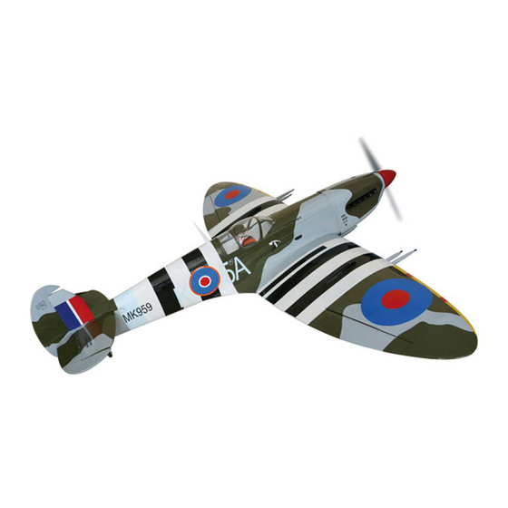
ASSEMBLY MANUAL
"Graphics and specifications may change without notice".
Specifications:
Wing span ------------------------------79.9in (203cm).
Wing area -----------------1165.6sq.in (75.2sq dm).
Weight ------------------------11-13.2lbs (5.0-6.0kg).
Length ------------------------------64.5in (163.8cm).
Engine ------------------------ 22-40cc -----2-stroke.
40-50cc -----4-stroke.
Radio ------------------- 6 channels with 10 servos.
Electric conversion: optional
Advertisement
Table of Contents

Related Manuals for Seagull Models Spitfire Mk IX


Summary of Contents for Seagull Models Spitfire Mk IX
- Page 1 MS:183 ASSEMBLY MANUAL “Graphics and specifications may change without notice”. Specifications: Wing span ------------------------------79.9in (203cm). Wing area -----------------1165.6sq.in (75.2sq dm). Weight ------------------------11-13.2lbs (5.0-6.0kg). Length ------------------------------64.5in (163.8cm). Engine ------------------------ 22-40cc -----2-stroke. 40-50cc -----4-stroke. Radio ------------------- 6 channels with 10 servos. Electric conversion: optional...
-
Page 2: Kit Contents
SPITFIRE - 2030 mm INTRODUCTION. Thank you for choosing the SPITFIRE 2030 mmARTF by SEAGULL MODELS COMPANY LTD. The SPITFIRE was designed with the intermediate/advanced sport flyer in mind. It is a semi scale airplane which is easy to fly and quick to assemble. The airframe is conventionally built using balsa, plywood to make it stronger than the average ARTF , yet the design allows the aeroplane to be kept light. - Page 3 www.seagullmodels.com HINGING THE FLAP . CONTENTSTS SEA18301 Fuselage SEA18302 Wing Set SEA18303 Tail Set SEA18304 Cowling SEA18305 Canopy SEA18306 Linkage Set SEA18307 Landing Gear SEA18308 Wing Tube SEA18309 Decal Set SEA18310 Hardware Pack 2x10 mm ADDITIONAL ITEMS REQUIRED. 22-40cc 2-stroke. 40-50cc 4-stroke.
- Page 4 Instruction Manual. SPITFIRE - 2030 mm Epoxy Fiberglass control horn. Epoxy Flap Fiberglass control horn. Epoxy Aileron Fiberglass control horn. INSTALL ELEVATOR CONTROL HORN. Epoxy Fiberglass control horn. INSTALL FLAP CONTROL HORN. Install the flap control horn using the same method as same as the aileron control horns.
-
Page 5: Installing The Fuselage Servos
www.seagullmodels.com INSTALLING THE FUSELAGE SERVOS. Elevator Fiberglass control horn. Because the size of servos differ, you may need to adjust the size of the precut opening in the mount. The notch in the sides of the mount allow the servo lead to pass through. 1) Install the rubber grommets and brass collets onto the throttle servo. - Page 6 Instruction Manual. SPITFIRE - 2030 mm INSTALLING THE SWITCH RECEIVER Install the switch into the precut hole in the side, in the fuselage. 3/ 32” Hole. Switch. INSTALLING THE STOPPER ASSEMBLY. 1) Using a modeling knife, carefully cut off the rear portion of one of the 3 nylon tubes leaving 1/2”...
-
Page 7: Fuel Tank Installation
www.seagullmodels.com You should mark which tube is the vent and which is the fuel pickup when you attach fuel tubing to the tubes in the stopper. Once the tank is installed inside the fuselage, it may be difficult to determine which is which. 7) Slide the fuel tank into the fuselage. -
Page 8: Engine Mount Installation
Instruction Manual. SPITFIRE - 2030 mm Blow through one of the lines to en- sure the fuel lines have not become kinked inside the fuel tank compartment. Air should flow through easily. ENGINE MOUNT INSTALLATION. 1) Locate the items necessary to install the engine mount included with your model. -
Page 9: Mounting The Engine
www.seagullmodels.com 4mm. Thread locker glue. MOUNTING THE ENGINE. 4) On the fire wall has the location for the throttle pusshrod tube (pre-drill). 1) Position the engine with the drive washer 5) Slide the pushrod tube in the firewall and (150mm) forward of the firewall as shown. guide it through the fuel tank mount. - Page 10 Instruction Manual. SPITFIRE - 2030 mm 8) Reinstall the servo horn by sliding the Secure the ignition module in the fuselage connector over the pushrod wire. Center the using hood and loop tape. Route the wires as throttle stick and trim and install the servo horn neccessary, making sure to connect the lead perpendicular to the servo center line.
-
Page 11: Installing The Spinner
www.seagullmodels.com Trim and cut. Because of the size of the cowl, it may be nec- essary to use a needle valve extension for the high speed needle valve. Make this out of suf- ficient length 1.5mm wire and install it into the end of the needle valve. - Page 12 Instruction Manual. SPITFIRE - 2030 mm 3) Use drill bit in a pin vise to drill the mouting INSTALLING THE AILERON SERVOS. holes in the blocks. 4) Apply 2-3 drops of thin C/A to each of the mounting holes. Allow the C/A to cure without Servos.
- Page 13 www.seagullmodels.com 9) Set the aileron hatch in place and use a Phillips screw driver to install it with four wood screws. 2x10 mm 8) A string has been provided in the wing to pull the aileron lead through to the wing root. Remove the string from the wing at the servo location and use the tape to attach it to the servo extension lead.
- Page 14 Instruction Manual. SPITFIRE - 2030 mm INSTALLING ELEVATOR SERVO The elevator servo assembly follow these be- low pictures C/A glue 2x10 mm...
- Page 15 www.seagullmodels.com AILERON PUSHROD HORN INSTALLATION Wing. M3 lock nut. 90mm. M3 clevis. M3 lock nut. Flap. INSTALLING THE PUSHROD ELEVATOR 60mm. M3 clevis. M3 lock nut. Wing. M3 lock nut. Fuel Tubing Metal Clevis Hex Nut Fuel Tubing Aileron. INSTALLING RETRACTABLE LANDING GEAR.
- Page 16 Instruction Manual. SPITFIRE - 2030 mm Pen. 2mm. 2mm. 30mm. M3 clevis. M3 lock nut. Screw. M3x25mm.
- Page 17 www.seagullmodels.com Epoxy Epoxy Collar 3) Install Wheel. 80mm Collar...
- Page 18 Instruction Manual. SPITFIRE - 2030 mm INSTALLING THE HORIZONTAL STABILIZER. INSTALLING RUDDER HINGE The rudder hinge assemblu follow picture below...
- Page 19 www.seagullmodels.com RUDDER PUSHROD HORN INSTALLATION. 1) Locate items necessary to install rudder pushrod. Crimp. M3 clevis. Cable end. Metal connector. Rudder pushrod. Metal Clevis Fuel Tubing Hex Nut...
-
Page 20: Mounting The Tail Wheel
Instruction Manual. SPITFIRE - 2030 mm MOUNTING THE TAIL WHEEL 1) Locate items necessary to install tail gear. Crimp. M3 clevis. Cable end. Metal connector. Collar Tail gear... - Page 21 www.seagullmodels.com Metal Clevis Fuel Tubing Hex Nut C/A glue INSTALLATION PILOT AND CANOPY. 1) Locate items necessary to install pilot and canopy. 2) A scale pilot is included with this ARF. The Seagull Pilot included fitting well to the cockpit. (or you can order others scale pilot figures made by Seagull factory.
-
Page 22: Apply The Decals
Instruction Manual. SPITFIRE - 2030 mm APPLY THE DECALS. 1) If all the decals are precut and ready to stick. Please be certain the model is clean and free from oily fingerprints and dust. Position decal on the model where desired, using the photos on the box and aid in their location. - Page 23 www.seagullmodels.com Remove covering to see hole Remove covering to see hole 5) Tighten the antenna to the fuselage. The antenna is removeable so you can install it at the flying field to prevent damage in trans- porting. Tighten the antenna...
- Page 24 Instruction Manual. SPITFIRE - 2030 mm ATTACHMENT WING-FUSELAGE. 1) Attach the aluminium tube into fuselage. Wing tube. Insert two wing panels as pictures below. BALANCING. 1) It is critical that your airplane be balanced correctly. Improper balance will cause your plane to lose control and crash. THE CENTER OF GRAVITY IS LOCATED 114 MM BACK FROM THE LEADING EDGE OF THE WING AT THE WING ROOT.
-
Page 25: Control Throws
www.seagullmodels.com With the wing attached to the fuselage, all CONTROL THROWS. parts of the model installed ( ready to fly), and empty fuel tanks, hold the model at the marked Ailerons: Rudder: balance point with the stabilizer level. High Rate : High Rate : Lift the model. -
Page 26: Flight Preparation
Instruction Manual. SPITFIRE - 2030 mm PREFLIGHT CHECK. FLIGHT PREPARATION. 1) Completely charge your transmitter Check the operation and direction of the and receiver batteries before your first day of elevator, rudder, ailerons and throttle. flying. A) Plug in your radio system per the 2) Check every bolt and every glue joint manufacturer's instructions and turn every- in the SPITFIRE to ensure that everything is...
Need help?
Do you have a question about the Spitfire Mk IX and is the answer not in the manual?
Questions and answers