Table of Contents
Advertisement
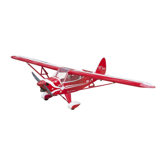
SAVAGE
WWW.SEAGULLMODELS.COM
CRUISER
MS: 195
ASSEMBLY MANUAL
"Graphics and specifications may change without notice".
Specifications:
Wingspan---------------79.9 in (203 cm).
Wing area---------------1001.3 sq.ins (64.6 sq.dm).
Weight-------------------9.7 - 10.6 lbs (4.4 - 4.8 kg).
Length-------------------58.8 in (149.3 cm).
Engine-------------------0.75 - 0.91 cu.in----2 stroke.
...................................1.00 - 1.25 cu.in----4 stroke.
Radio--------------------6 channels with 11 servos.
Electric conversion: Optional.
1
Advertisement
Table of Contents

Related Manuals for Seagull Models Savage Cruiser


Summary of Contents for Seagull Models Savage Cruiser
- Page 1 SAVAGE WWW.SEAGULLMODELS.COM CRUISER MS: 195 ASSEMBLY MANUAL “Graphics and specifications may change without notice”. Specifications: Wingspan---------------79.9 in (203 cm). Wing area---------------1001.3 sq.ins (64.6 sq.dm). Weight-------------------9.7 - 10.6 lbs (4.4 - 4.8 kg). Length-------------------58.8 in (149.3 cm). Engine-------------------0.75 - 0.91 cu.in----2 stroke........1.00 - 1.25 cu.in----4 stroke.
-
Page 2: Kit Contents
The motor mount has been fit- ted and the hinges are pre-installed. Flying the SAVAGE CRUISER is simply a joy. This instruction manual is designed to help you build a great flying earoplane. Please read this manual throughly before starting assembly of your SAVAGE CRUISER User the parts listing below to indentify all parts. -
Page 3: Additional Items Required
WWW.SEAGULLMODELS.COM HINGING THE FLAP. KIT CONTENTS . Note: The control surfaces, including the SEA19501 Fuselage ailerons, elevators, and rudder, are prehinged SEA19502 Wing Set with hinges installed, but the hinges are not SEA19503 Tail Set glued in place. It is imperative that you prop- SEA19504 Fiberglass Cowling erly adhere the hinges in place per the steps that follow using a high-quality thin C/A glue. -
Page 4: Hinging The Aileron
SAVAGE CRUISER Instruction Manual. 8) After both flap are securely hinged, firmly grasp the wing panel and flap to make sure the hinges are securely glued and can- not be pulled out. Do this by carefully apply- ing medium pressure, trying to separate the flap from the wing panel. - Page 5 WWW.SEAGULLMODELS.COM T-pin. C/A glue. C/A Hinge. 3) Slide the aileron on the wing panel until there is only a slight gap. The hinge is now centered on the wing panel and aileron.Re- move the T-pins and snug the aileron against the wing panel.
-
Page 6: Hinging The Elevator
SAVAGE CRUISER Instruction Manual. 8) After both ailerons are securely hinged, INSTALL THE. firmly grasp the wing panel and aileron to make sure the hinges are securely glued and cannot be pulled out. Do this by carefully ap- plying medium pressure, trying to separate the aileron from the wing panel. - Page 7 WWW.SEAGULLMODELS.COM INSTALL THE AILERONS INSTALL ELEVATOR CONTROL HORN CONTROL HORN. Fiberglass control horn. Fiberglass control horn. Elevator Fiberglass control horn. Aileron Fiberglass control horn. Epoxy. INSTALL FLAP CONTROL HORN. INSTALL ELEVATOR CONTROL HORN Install the flap control horn using the Repeat steps to install the rudder control same method as same as the aileron con- horn as same as steps done for ailerons.
-
Page 8: Engine Mount Installation
SAVAGE CRUISER Instruction Manual. 2) Using a modeling knife, cut one length of ENGINE MOUNT INSTALLATION. silicon fuel line. Connect one end of the line 1) Locate the items necessary to install the to the weighted fuel pick up and the other engine mount included with your model. -
Page 9: Fuel Tank Installation
WWW.SEAGULLMODELS.COM 8) Use plywood template to hold in place 3) Carefully bend the second nylon tube the fuel tank with C/A glue to secure the fuel up at a 45º angle. This tube is the vent tube. tank inside the fuselage. 4) Test fit the stopper assembly into the tank. -
Page 10: Installing The Fuselage Servos
SAVAGE CRUISER Instruction Manual. INSTALLING THE FUSELAGE SERVOS Because the size of servos differ, you may need to adjust the size of the precut opening in the mount. The notch in the sides of the mount allow the servo lead to pass through. -
Page 11: Installing The Switch
WWW.SEAGULLMODELS.COM INSTALLING THE SWITCH. Install the switch into the precut hole in the side, in the fuselage. 3/32” Hole. 4x20 mm Thread locker glue. M4 x 20 mm Switch 4x20 mm INSTALLING THE MAIN LANDING GEAR TO FUSELAGE. 4x20 mm... - Page 12 SAVAGE CRUISER Instruction Manual. Wheel collar. Wheel. Washer. nut.-- Wheel Pant. C/A glue. Landing gear. Wheel pant. C/A glue. 4x10 mm 4x10 mm INSTALLING WHEEL PANTS TO MAIN LANDING GEAR. Locker glue. Wheel collar. Axle. Washer. Wheel.
-
Page 13: Mounting The Engine
WWW.SEAGULLMODELS.COM 4) On the fire wall has the location for the MOUNTING THE ENGINE throttle pusshrod tube (pre-drill). 1) Position the engine with the drive washer (145mm) forward of the firewall as 5) Slide the pushrod tube in the firewall shown. - Page 14 SAVAGE CRUISER Instruction Manual. Cut. 9) Move the throttle stick to the closed position and move the carburetor to closed. Use a 2.5mm hex wrench to tighten the screw that secures the throttle pushrod wire. Make sure to use threadlock on the screw so it does not vibrate loose.
- Page 15 WWW.SEAGULLMODELS.COM - Model size: .90 size models - Motor: 50mm 310 rev per volt - Propeller: 15x10 ~ 16x10 - ESC: 80A - Lipo Batteries: 8 cell 5200mA 2) Attach the electric motor box to the firewall suitable with the cross lines drawn on the electric motor box and firewall.
- Page 16 SAVAGE CRUISER Instruction Manual. Epoxy. 150 mm Balsa stick. Epoxy. Electric motor. 4) Locate the plywood battery tray to the fuselage. Tighten the screws using machine screws M3x15mm to secure the tray in position. Blind nut M3 3x15mm 3x15mm...
-
Page 17: Installing The Spinner
WWW.SEAGULLMODELS.COM The propeller should not touch any part of the spinner cone. If it does, use a sharp mod- eling knife and carefully trim away the spinner cone where the propeller comes in contact with 5) Attach the speed control to the side of the motor box using two-sided tape and tie wraps. - Page 18 SAVAGE CRUISER Instruction Manual. 7) Apply 1-2 drops of thin C/A to each of the mounting tabs. Allow the C/A to cure without using accelerator. 3) Use drill bit in a pin vise to drill the mouting holes in the blocks.
- Page 19 WWW.SEAGULLMODELS.COM AILERON PUSHROD HORN INSTALLATION. 90mm M3 clevis. M3 lock nut. 9) Set the aileron hatch in place and use a Phillips screw driver to install it with four wood screws. 2x10mm M3 clevis. Fuel Tubing. INSTALLING THE FLAP SERVO. Hex Nut.
- Page 20 SAVAGE CRUISER Instruction Manual. INSTALLING THE FLAP SERVO. Cut. Repeat the procedure for the aileron servo. 80mm 3) Slide the stabilizer into place in the M3 clevis. M3 lock nut. precut slot in the rear of the fuselage. The stabilizer should be pushed firmly against the front of the slot.
- Page 21 WWW.SEAGULLMODELS.COM INSTALLING VERITICAL STABILIZER. When cutting through the covering to remove it, cut with only enough pressure to only cut through the covering itself. Cutting into the balsa structure may weaken it. 6) Using a modeling knife, carefully re- move the covering that overlaps the stabiliz- er mounting platform sides in the fuselage.
- Page 22 SAVAGE CRUISER Instruction Manual. Epoxy. Elevator control horn. Rudder control horn. M2 lock nut M2 clevis. 600mm Metal connector Crimp. 4) When you are sure that everything is aligned correctly, mix up a generous M3 clevis. amount of Flash 30 Minute Epoxy. Ap-...
- Page 23 WWW.SEAGULLMODELS.COM Pushrod Hex Nut. Fuel Tubing. M3 clevis. M2 clevis. 3x15 mm INSTALLING TAILWHEEL. 1) Locate the items for this section of the 115mm manual. INSTALLING TAIL STRUTS SUPPORT. The tail struct system assembly follow picture below 3x20 mm...
- Page 24 SAVAGE CRUISER Instruction Manual. Metal connector. Hex nut. Crimp. M3 clevis. Cable end. INSTALLING BATTERY-RECIEVER. 1) Plug the five servo leads and the switch lead into the receiver. Plug the bat- tery pack lead into the switch also. 2) Wrap the receiver and battery pack in the protective foam rubber to protect them from vibration.
-
Page 25: Apply The Decals
WWW.SEAGULLMODELS.COM Battery. 3x15mm Receiver. INSTALLING BATTERY-RECIEVER. 1) Locate items necessary to install pilot, C/A glue. seats. APPLY THE DECALS. 1) If all the decals are precut and ready to stick. Please be certain the model is clean and free from oily fingerprints and dust. Position decal on the model where desired, using the photos on the box and aid in their location. - Page 26 SAVAGE CRUISER Instruction Manual. Epoxy Epoxy Wing Bolt. 4x20mm Epoxy INSTALLATION STRUT WING-FUSELAGE. Epoxy...
- Page 27 WWW.SEAGULLMODELS.COM Epoxy Epoxy 3x15mm 3x15mm Screw.
- Page 28 SAVAGE CRUISER Instruction Manual. BALANCING. 1)It is critical that your airplane be bal- anced correctly. Improper balance will cause your plane to lose control and crash. THE CENTER OF GRAVITY IS LOCATED 90 MM BACK FROM THE LEADING EDGE OF THE WING AT THE WING ROOT.
-
Page 29: Control Throws
WWW.SEAGULLMODELS.COM *If possible, first attempt to balance the CONTROL THROWS. model by chaning the position of the re- ceiver battery and receiver. If you are un- able to obtain good balance by doing so, Rudder: Ailerons: then it will be necessary to add weight to High Rate : High Rate : the nose or tail to achieve the proper bal-... -
Page 30: Flight Preparation
A) Plug in your radio system per the man- ufacturer’s instructions and turn everything 2) Check every bolt and every glue joint in the SAVAGE CRUISER to ensure that every- B) Check the elevator first. Pull back on thing is tight and well bonded.
Need help?
Do you have a question about the Savage Cruiser and is the answer not in the manual?
Questions and answers