Table of Contents
Advertisement
Quick Links
Instruction Manual.
A S S E M B L Y M A N U A L
Code: SEA250
" Graphics and specifications may change without notice ".
( SEA250P)
Specifications:
Wingspan---------------80 in ( 203.2 cm).
Wing area---------------1094.3 sq.in ( 70.6 sq.dm).
Weight-------------------15.4 -15.9 lbs ( 7.0-7.2 kg).
Length-------------------63.6 in ( 161.5 cm).
Engine-------------------33-38cc
Motor size---------------Power 160
(SEA250S)
Radio--------------------6 channels with 10 servos.
Electric Power Conversion Optional.
1
Advertisement
Table of Contents

Related Manuals for Seagull Models CURTISS P-40N WARHAWK


Summary of Contents for Seagull Models CURTISS P-40N WARHAWK
- Page 1 Instruction Manual. A S S E M B L Y M A N U A L Code: SEA250 “ Graphics and specifications may change without notice ”. ( SEA250P) Specifications: Wingspan---------------80 in ( 203.2 cm). Wing area---------------1094.3 sq.in ( 70.6 sq.dm). Weight-------------------15.4 -15.9 lbs ( 7.0-7.2 kg).
-
Page 2: Kit Contents
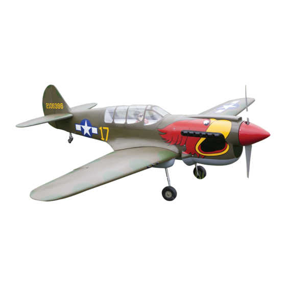
Curtiss P-40N Warhawk INTRODUCTION. Thank you for choosing the CURTISS P-40N WARHAWK ARF by SG MODELS . The CUR- TISS P-40N WARHAWK was designed with the intermediate/advanced sport flyer in mind. It is a semi scale airplane which is easy to fly and quick to assemble. The airframe is conven- tionally built using balsa, plywood to make it stronger than the average ARF, yet the design allows the aeroplane to be kept light. -
Page 3: Additional Items Required
Instruction Manual. HINGING THE FLAP. KIT CONTENTS. SEA25001 Fuselage SEA25002 Wing set SEA25003 Tail set SEA25004 Canopy SEA25005 Cowling SEA25006 Aluminium tube SEA25007 Pilot ADDITIONAL ITEMS REQUIRED. 33cc-38cc gasoline engine. � Power 160 � Computer radio with 10 servos. � Glow plug to suit engine. -
Page 4: Hinging The Aileron
Curtiss P-40N Warhawk Hinge. 3) Slide the wing panel on the aileron until there is only a slight gap. The hinge is now centered on the wing panel and aileron. Re- move the T-pins and snug the aileron against the wing panel. A gap of 1/64” or less should be maintained between the wing panel and aileron. -
Page 5: Install The Ailerons
Instruction Manual. 5) Turn the wing panel over and deflect the aileron in the opposite direction from the opposite side. Apply thin C/A glue to each hinge, making sure that the C/A penetrates into both the aileron and wing panel. Epoxy. -
Page 6: Wing Assembly
Curtiss P-40N Warhawk Epoxy. WING ASSEMBLY. Please see below pictures. INSTALLING THE AILERON SERVOS. Epoxy. Attach the aluminum tube into wing. Servos Small weight Thread... - Page 7 Instruction Manual. 5) Use dental floss to secure the connec- Because the size of servos differ, you tion so they cannot become unplugged. may need to adjust the size of the precut opening in the mount. The notch in the sides of the mount allow the servo lead to pass through.
-
Page 8: Aileron Pushrod Installation
Curtiss P-40N Warhawk INSTALLING THE FLAP SERVO. Repeat the procedure for the flap servo. AILERON PUSHROD INSTALLATION. Please see below pictures. 9) Set the aileron hatch in place and use a Phillips screw driver to install it with four wood screws. - Page 9 Instruction Manual. SERVO ROTATING RETRACT M3 clevis. M3 lock nut. LANDING GEAR. Please see below pictures. INSTALLING THE FLAP PUSHROD. Repeat the procedure for the aileron pushrod. 35mm M3 clevis. M3 lock nut.
- Page 10 Curtiss P-40N Warhawk 3x25mm 45mm M3 lock nut. M3 clevis.
- Page 11 Instruction Manual. Collar. Epoxy. Epoxy. Collar.
-
Page 12: Installing The Fuselage Servos
Curtiss P-40N Warhawk Loctite secure. Adjustable servo connector. Servo arm. Throttle servo arm. INSTALLING THE FUSELAGE SERVOS. Because the size of servos differ, you may need to adjust the size of the precut opening in the mount. The notch in the sides of the mount allow the servo lead to pass through. -
Page 13: Installing The Stopper Assembly
Instruction Manual. Switch. INSTALLING THE ENGINE SWITCH. Trim and cut. Switch. Vent tube. Fuel pick up INSTALLING THE STOPPER Fuel fill tube. ASSEMBLY. 1) Using a modeling knife, carefully cut 3) Carefully bend the second nylon tube up off the rear portion of one of the 3 nylon at a 45º... -
Page 14: Fuel Tank Installation
Curtiss P-40N Warhawk 5) With the stopper assembly in place, the weighted pick-up should rest away from the rear of the tank and move freely inside the tank. The top of the vent tube should rest just below the top of the tank. It should not touch the top of the tank. - Page 15 Instruction Manual. 5x80mm Reinstall the servo horn by sliding the connector over the pushrod wire. Center the throttle stick and trim and install the servo horn perpendicular to the servo center line.
- Page 16 Curtiss P-40N Warhawk Cut. Move the throttle stick to the closed po- sition and move the carburetor to closed. Use a 2.5mm hex wrench to tighten the screw that secures the throttle pushrod wire. Make sure to use threadlock on the screw so it does not vibrate loose.
-
Page 17: Hinging The Elevator
Instruction Manual. The propeller should not touch any part of the spinner cone. If it does, use a sharp modeling knife and carefully trim away the spinner cone where the propel- ler comes in contact with it. 3x10mm 2) Install the muffler and muffler extension onto the engine and make the cutout in the cowl for muffler clearance. - Page 18 Curtiss P-40N Warhawk INSTALL RUDDER CONTROL HORN. Repeat steps to install the rudder control horn as same as steps done for ailerons. Epoxy. Fiberglass control horn Epoxy. Epoxy. Elevator fiberglass control horn. Use knife to remove covering Rudder fiberglass control horn.
-
Page 19: Installing Horizontal Stabilizer
Instruction Manual. INSTALLING HORIZONTAL STABILIZER. ELEVATOR PUSHROD INSTALLATION. 1) Locate items necessary to install eleva- tor pushrod. Elevator control horn. 2) Elevator pushrods assembly as pic- tures below. M2 clevis. M2 lock nut. Vertical Stabilizer. Horizontal 90º Stabilizer. -
Page 20: Rudder Pushrod Installation
Curtiss P-40N Warhawk RUDDER PUSHROD INSTALLATION. 1) Locate items necessary to install rud- der pushrod. Rudder control horn. 2) Rudder pushrods assembly as pictures below. M2 clevis. M2 lock nut. Elevator pushrod. -
Page 21: Mounting The Tail Wheel
Instruction Manual. Rudder pushrod. MOUNTING THE TAIL WHEEL. M2 clevis. M2 lock nut. - Page 22 Curtiss P-40N Warhawk INSTALLATION PILOT AND CANOPY. 1) Locate items necessary to install pilot, seats. Epoxy.
-
Page 23: Apply The Decals
Instruction Manual. 2) A scale pilot is included with this ARF. The Pilot included fitting well to the cockpit. (or you can order others scale pilot figures made by SG-Models. They are available at SG-Models distributors.) If you are going to install a pilot figure, Epoxy. - Page 24 Curtiss P-40N Warhawk ATTACHMENT WING- FUSELAGE.
- Page 25 Instruction Manual. Insert wing gun onto the wings. BALANCING. 1) It is critical that your airplane be balanced correctly. Improper balance will cause your plane to lose control and crash. THE CENTER OF GRAV- ITY IS LOCATED 100MM BACK FROM THE LEADING EDGE OF THE WING AT THE WING ROOT.
-
Page 26: Control Throws
Curtiss P-40N Warhawk Accurately mark the balance point on the top of the wing on both sides of the fuselage. The balance point is located 100mm 100mm back from the leading edge of the wing at the wing root. This is the bal- ance point at which your model should balance for your first flights. - Page 27 Instruction Manual.
-
Page 28: Flight Preparation
An out of balance propeller will cause If it does not, flip the servo reversing excessive vibration which could lead switch on your transmitter to change to engine and/or airframe failure. the direction. We wish you many safe and enjoyable flights with your CURTISS P-40N WARHAWK.
Need help?
Do you have a question about the CURTISS P-40N WARHAWK and is the answer not in the manual?
Questions and answers