Table of Contents
Advertisement
Quick Links
Hand-made Almost R
Hand-made
Hand-made
Hand-made
Hand-made
Specifications
Wingspan---------------------------------------60.63in, 1540mm.
Wing area--------------------------------610 sq.in, 37.04sq.dm.
Fuselage length--------------------------------43.7in, 1110mm.
Approximate flying weight---------5.5-5.95lbs, 2500-2700g.
Recommended engine size---------.40-.58 cu.in. 2-stroke.
----------------------------------------------.50-.72 cu.in. 4-stroke.
Recommended R/C-----------------------4 channel minimum.
Flying skill level-------------------------Intermediate/advanced.
Kit features.
•
Ready-made—minimal assembly & finishing required.
•
Factory-installed pushrods.
•
Comprehensive hardware pack including wheels, tank,
undercarriage & spinner.
•
Photo-illustrated step-by-step Assembly Manual.
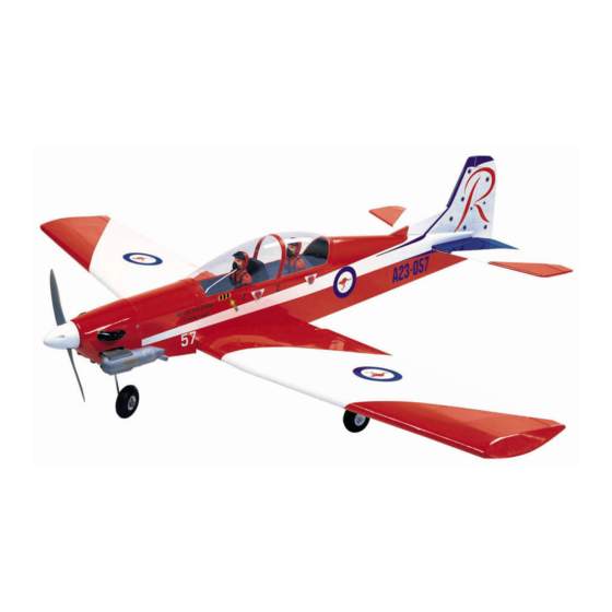
PC-9
semi Scale ARF Model
Almost R
Almost Read
Almost R
ead
ead
eady to F
Almost R
ead
Aircraft
Aircraft
Aircraft
Aircraft
Aircraft
ASSEMBL
ASSEMBL
Y MANU
Y MANU
ASSEMBL
ASSEMBL
ASSEMBLY MANU
Y MANUAL
Y MANU
y to Fl l l l l y R/C Model
y to F
y to F
y R/C Model
y R/C Model
y R/C Model
y to F
y R/C Model
AL
AL
AL
AL
Additional items required.
Engine.
4 Channel or greater Radio Control system.
Glues.
Tools.
Starting Equipment.
MS:12
Made in Vietnam.
Advertisement
Table of Contents

Subscribe to Our Youtube Channel
Related Manuals for Seagull Models SEA12


Summary of Contents for Seagull Models SEA12
- Page 1 PC-9 semi Scale ARF Model Hand-made Hand-made Almost R Hand-made Almost R Almost Read Almost R eady to F y to F y to Fl l l l l y R/C Model y to F y R/C Model y R/C Model y R/C Model Hand-made Hand-made...
-
Page 2: Fuselage Assembly
INTRODUCTION. Thank you for choosing the PC-9 ARTF by SG MODELS. The PC-9 was designed with the intermediate/advanced sport flyer in mind. It is a low-wing scale aeroplane which is easy to fly and quick to assemble. The airframe is conventionally built using balsa, plywood and veneer to make it stronger than the average ARTF , yet the design allows the aeroplane to be kept light. -
Page 3: Hinging The Ailerons
NOTE: To avoid scratching your new aero- HINGING THE AILERONS. plane we suggest that you cover your workbench with an old towel. Note: The control surfaces, including the Keep a couple of jars or bowls handy ailerons, elevators, and rudder, are to hold the small parts after you open prehinged with hinges installed, but the the bags. -
Page 4: Hinging The Elevator
PC-9 Instruction Manual. hinges are glued in place, a 1/64” gap or less will be maintained throughout the lengh of the aileron to the wing panel hinge line. Note: The hinge is constructed of a special material that allows the C/A to wick or penetrate and distribute throughout the hinge, securely bonding it to the wood Note:... -
Page 5: Hinging The Rudder
HINGING THE RUDDER. Glue the elevator hinges in place using the same techniques used to hinge the ailerons. Epoxy. Carefully slide the two wing halves together and firmly press them together, allowing the excess epoxy to run out. There should not be any gap in the wing halves. -
Page 6: Installing The Aileron Servos
PC-9 Instruction Manual. Thread. Remove covering. Small weight. Glue attached. INSTALLING THE AILERON SERVOS. Thread. 3) Attach servo lead to the aileron servo. Small Attach the string to the servo lead and care- weight. fully thread it though the wing. Once you have thread the lead throught the wing, remove the string so it can use for the other servo lead. -
Page 7: Aileron Linkage
AILERON LINKAGE. 1) Using a ruler & pen to draw a straight line as below picture. Thread. 4) Tape the servo lead to the wing to pre- Pen. vent it from falling back into the wing. Plastic tape. Straight line. 5) Reinstall the servo into the servo mount and secure the servo inplace using the wood screws provided with you radio system. -
Page 8: Installing The Main Gear Wires
PC-9 Instruction Manual. 4) Using a 1mm drill bit and the control 8) Make a 90-degree bend at the mark horns as a guide, drill the mounting holes and cut off the excess wire leaving 10mm past through the aileron halves. the bend. -
Page 9: Nose Gear Installation
3) The landing gear wire is held in place 8) Slide one 60mm diameter wheel onto using two nylon landing gear straps and four each axle and push them up against the wheel 3mm x 12mm wood screws. collars. Slide the remaining wheel collars with 3mm x 6mm set screws onto the axles. -
Page 10: Installing The Stopper Assembly
PC-9 Instruction Manual. FUEL TANK. Install the pushrod wire as shown. INSTALLING THE STOPPER ASSEMBLY. 1) Using a modeling knife, carefully cut Adjustable off the rear portion of one of the two nylon tubes Connector. leaving 1/2” protruding from the rear of the stopper. -
Page 11: Installing The Fuel Tank
4) Carefully heat the vent tube using a INSTALLING THE FUEL TANK. heat gun or lighter to permanently set the angle of the tube. Vent tube. Fuel Pickup Tube. Fuel Fill Tube. When the stopper assembly is installed in the tank, the top of the vent tube should rest just below the top surface of the tank. -
Page 12: Mounting The Engine
PC-9 Instruction Manual. Vent tube. 5) Attach the Z-Bend in the pushrod wire to the throttle arm on the carburetor. You will need to remove the throttle arm from the car- buretor to be able to attach the Z-bend. When complete, reattach the throttle arm to the car- Fuel fill tube. - Page 13 ELECTRIC POWER CONVERSION. 1) Locate the items necessary to install the electric power conversion included with your model. 4) Attach the motor to the front of the electric motor box using four 4mm blind nut, four M3x15mm hex head bolts to se- cure the motor.
- Page 14 Instruction Manual. M3x15mm Epoxy 11cm...
- Page 15 Speed control. Battery. M3x15mm Air exit hole.
- Page 16 4) Remove the cowl. Using a 5/64” drill COWLING. bit, enlarge the holes in only the four cowl blocks. 5) Using a 1/8” drill bit. Enlarging the holes through the cowl will prevent the fiberglass from splitting when the mounting screws are installed.
-
Page 17: Installing The Switch
PC-9 Instruction Manual. INSTALLING THE SWITCH. 1) Install the switch into the precut hole INSTALLING THE SPINNER. in the servo tray, in the fuselage, from the bot- tom. Use the two screws provided with the Install the spinner backplate, propeller switch to secure it in place. -
Page 18: Installing The Fuselage Servos
3) Slide the stabilizer into place in the pre- INSTALLING THE FUSELAGE SERVOS. cut slot in the rear of the fuselage. The stabi- lizer should be pushed firmly against the front of the slot. 4) When you are satisfied with the align- ment, hold the stabilizer in place with T- pins or masking tape, but do not glue at this time. -
Page 19: Vertical Stabilizer Installation
PC-9 Instruction Manual. in the fuselage. Slide the stabilizer in place 2) Slide the vertical stabilizer into the slot and realign. Double check all of your mea- in the top of the fuselage. The rear edge of surements once more before the epoxy cures. the stabilizer should be flush with the rear edge Hold the stabilizer in place with T-pins or mask- of the fuselage and the lower rudder hinge... -
Page 20: Control Horn Installation
2) Position the two elevator horns on the bottom side of each elevator. The clevis at- tach- ment holes should be positioned over the hinge line. 2mm X 20mm. Remove covering. 5) Slide the vertical stabilizer back in place. Using a triangle, check to ensure that the vertical stabilizer is aligned 90º... -
Page 21: Installation
PC-9 Instruction Manual. ELEVATOR-RUDDER PUSHROD Cut. INSTALLATION. Rubber Antenna. Band. Modified Servo Arm. Battery. Tie wrap. Elevator pushrod. Clevis. Rudder pushrod. Control horn. Receiver. ATTACHMENT WING - FUSELAGE. See picture below: Rudder. Switch. Throttle. BALANCING. Elevator. 1) It is critical that your airplane be bal- anced correctly. -
Page 22: Preflight Check
4) If the nose of the plane falls, the plane INITIAL FLYING/SPORT FLYING is nose heavy. To correct this first move the Ailerons: 3/16” up 3/16” down battery pack further back in the fuselage. If this is not possible or does not correct it, stick Elevator: 5/16”...
Need help?
Do you have a question about the SEA12 and is the answer not in the manual?
Questions and answers