Seagull Models YAK 54 Assembly Manual
Arf 20cc
Hide thumbs
Also See for YAK 54:
- Assembly manual (24 pages) ,
- Assembly manual (21 pages) ,
- Assembly manual (37 pages)
Table of Contents
Advertisement
Quick Links
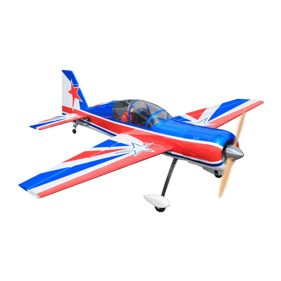
Code : SEA 387
ASSEMBLY MANUAL
Speciications:
Wingspan ----------------- 64 in---------------------- 162.5 cm.
Wing Area ---------------- 846 sp.in----------------- 54.6 sq.dm.
Weight --------------------- 9.3 lbs-------------------- 4.2 kg.
Length --------------------- 61.4 in-------------------- 156 cm.
Engine size .91-1.25 cu.in- 2-4stroke / 20cc gasoline engine.
Radio System------------- 5 channel with 5 digital servos.
1
Advertisement
Table of Contents

Related Manuals for Seagull Models YAK 54


Summary of Contents for Seagull Models YAK 54
- Page 1 Code : SEA 387 ASSEMBLY MANUAL Speciications: Wingspan ----------------- 64 in---------------------- 162.5 cm. Wing Area ---------------- 846 sp.in----------------- 54.6 sq.dm. Weight --------------------- 9.3 lbs-------------------- 4.2 kg. Length --------------------- 61.4 in-------------------- 156 cm. Engine size .91-1.25 cu.in- 2-4stroke / 20cc gasoline engine. Radio System------------- 5 channel with 5 digital servos.
-
Page 2: Kit Contents
YAK 54 ARF 20cc Instruction Manual. INTRODUCTION YAK 54 ARF 20cc YAK 54 hank you for choosing the ARTF by SG MODELS. he ARF 20cc was designed with the intermediate/advanced sport lyer in mind. It is a semi scale airplane which is easy to ly and quick to assemble. he airframe is conventionally built using balsa, plywood to make it stronger than the average ARTF, yet the design allows the aeroplane to be kept light. -
Page 3: Hinging The Aileron
KIT CONTENTS HINGING THE AILERON SEA387 YAK 54 ARF 20cc Note : he control surfaces, including the ailer- ons, elevators, and rudder, are prehinged with 1. Fuselage hinges installed, but the hinges are not glued in 2. Wing set (2) place. - Page 4 YAK 54 ARF 20cc Instruction Manual. Delect the aileron and completely saturate each hinge with thin C/A glue. he ailerons front surface should lightly contact the wing during this procedure. Ideally, when the hinges are glued in place, a 1/64” gap or less will be maintained throughout the lengh of the aileron to the wing panel hinge line.
- Page 5 Place low-tack tape 1/32 inch (1mm) INSTALL THE AILERONS from the control horn slot. his will pre- CONTROL HORN vent epoxy from getting on the control surface when the control horns are glued Locate the aileron control horns. he taller in place.
-
Page 6: Installing The Aileron Servos
YAK 54 ARF 20cc Instruction Manual. Before the epoxy fully cures, remove Maximum Servo spec. the tape from around the control horn. Torque : 126.6 oz-in (9.11 kg-cm) @ 6.0V; his will allow the epoxy to low around 178 oz-in (12.82 kg-cm) @ 7.4V; 248 oz- the control horn, creating a small ilet in (17.86 kg-cm) @ 8.4V... - Page 7 Tape the servo lead to the wing to pre- vent it from falling back into the wing. 25mm Reinstall the servo into the servo mount and secure the servo inplace using the wood screws provided with you radio system. Repeat the procedure for the other wing half.
- Page 8 YAK 54 ARF 20cc Instruction Manual. INSTALLING THE AILERON PUSHROD Please study images below. Repeat all the above steps for the other wing. INSTALL HINGE FOR STABILIZER AND ELEVATOR Please study images below. 65mm...
- Page 9 40mm 40mm Epoxy CA glue...
- Page 10 YAK 54 ARF 20cc Instruction Manual. Epoxy Epoxy INSTALL ELEVATOR CONTROL HORN Fiberglass control horn...
- Page 11 Maximum Servo spec. Torque : 126.6 oz-in (9.11 kg-cm) @ 6.0V; 178 oz-in (12.82 kg-cm) @ 7.4V; 248 oz- in (17.86 kg-cm) @ 8.4V...
- Page 12 YAK 54 ARF 20cc Instruction Manual.
- Page 13 INSTALLING THE HORIZONTAL STABILIZER Using a ruler and a pen, locate the cen- terline of the horizontal stabilizer, at the trailing edge, and place a mark. Use a tri- angle and extend this mark, from back to front, across the top of the stabilizer. Also extend this mark down the back of the trailing edge of the stabilizer.
-
Page 14: Hinging The Rudder
YAK 54 ARF 20cc Instruction Manual. When cutting through the covering to remove it, cut with only enough pressure to only cut through the covering itself. Cut- ting into the balsa structure may weaken Using a modeling knife, carefully re-... - Page 15 CA glue Epoxy INSTALL RUDDER CONTROL HORN Repeat steps to install the rudder control horn as same as steps done for elevator. Fiberglass control horn...
-
Page 16: Installing Vertical Stabilizer
YAK 54 ARF 20cc Instruction Manual. Remove covering Fill Epoxy Epoxy Rudder iberglass control horn Slide the vertical stabilizer into the slot in the top of the fuselage. he rear edge of the INSTALLING VERTICAL STABILIZER stabilizer should be lush with the rear edge... -
Page 17: Installation
ELEVATOR PUSHROD INSTALLATION Epoxy Slide the vertical stabilizer back inplace. Using a triangle, check to ensure that the vertical stabilizer is aligned 90º to the horizontal stabilizer. Vertical Stabilizer. Horizontal 90º Stabilizer. 125mm When you are sure that everything is aligned correctly, mix up a generous amount of Flash 30 Minute Epoxy. -
Page 18: Rudder Pushrod Installation
YAK 54 ARF 20cc Instruction Manual. RUDDER PUSHROD TAILWHEEL INSTALLATION INSTALLATION Locate items necessary to install Locate items necessary to install rudder tailwheel. pushrod. 95mm... - Page 19 C/A glue M3x15mm M3x12mm...
- Page 20 YAK 54 ARF 20cc Instruction Manual. INSTALLING THE MAIN LANDING GEAR TO FUSELAGE Please study images below.
- Page 21 3x4mm 3x4mm...
- Page 22 YAK 54 ARF 20cc Instruction Manual. 3x10mm Loctite M3x12mm...
- Page 23 M4x20mm INSTALLING THE RECEIVER SWITCH Loctite Install the switch into the precut hole in the side, in the fuselage. Trim and cut M4x20mm Switch...
-
Page 24: Fuel Tank Installation
YAK 54 ARF 20cc Instruction Manual. FUEL TANK INSTALLATION ENGINE MOUNT INSTALLATION Locate the items necessary to install the You should mark which tube is the vent engine mount included with your model. and which is the fuel pickup when you attach fuel tubing to the tubes in the stopper. -
Page 25: Mounting The Engine
hread locker glue Use a drill to drill the four holes in the engine mount rails. MOUNTING THE ENGINE he ire wall has the location for the Position the engine with the drive throttle pushrod tube (pre-drill). washer (145mm) forward of the iewall as shown. -
Page 26: Throttle Servo Installation
YAK 54 ARF 20cc Instruction Manual. Machine screw M4x30mm Attach throttle pushrod to the carbure- tor throttle arm with the ball link. THROTTLE SERVO INSTALLATION Install adjustable servo connector in the servo arm as same as picture below: servo arm Use a 1/4”... -
Page 27: Ignition Installation
IGNITION INSTALLATION I hread nylon tie through mounting holes. Reinstall the servo horn by sliding the connector over the pushrod wire. Center the throttle stick and trim and install the servo horn perpendicular to the servo center line. Connect ignition module to pickup line of Move the throttle stick to the closed po- engine. - Page 28 YAK 54 ARF 20cc Instruction Manual. COWLING Please study images below.
- Page 29 Install the muler and muler extension onto the engine and make the cutout in the cowl for muler clearance. Connect the fuel and pressure lines to the carburetor, muler and fuel iler valve. Secure the cowl to fuselage using the M3x10mm socket head screws.Putting a small length of silicon fuel tube under the head of the screw helps with vibration.
- Page 30 YAK 54 ARF 20cc Instruction Manual. ELECTRIC POWER CONVERSION Locate the items neccessary to install the electric power conversion included with your model. M4x25mm and washers Attach the motor mount to the front of the electric motor box using four 4mm blind nut, four M4x25mm hex head bolts to se- cure the motor.
- Page 31 hen, use 4mm drill bit to enlarge the holes on the electric motor box. M4x20mm Blind nut 145mm Balsa stick Attach the motor to the front of the elec- tric motor box using four 4mm blind nut, four M4x20mm hex head bolts to secure the motor.
-
Page 32: Installing The Spinner
YAK 54 ARF 20cc Instruction Manual. Speed control he propeller should not touch any part of the spinner cone. If it does, use a sharp modeling knife and carefully trim away the spinner cone where the propel- ler comes in contact with it. - Page 33 Epoxy Epoxy...
- Page 34 YAK 54 ARF 20cc Instruction Manual. ATTACHMENT WING - FUSELAGE Attach the aluminium tube into fuselage. Wing tube Epoxy INSTALLING THE BATTERY-RECEVER Plug the servos leads and the switch lead into the receiver. Plug the battery pack lead into the switch also.
-
Page 35: Apply The Decals
2) he recommended Center of Grav- ity (CG) location for your model is (70- 80mm) back from the leading edge at the center of the wing. 3) When balancing your model, make sure it is assembled and ready for light. Support the plane upright at the marks made on the wing with your igers or a commercially available balancing stand. -
Page 36: Control Throws
YAK 54 ARF 20cc Instruction Manual. CONTROL THROWS Ailerons: Rudder: High Rate : High Rate : Up : 50 mm Right : 60 mm Down : 50 mm Let : 60 mm Low Rate : Low Rate : Up : 25 mm... -
Page 37: Flight Preparation
2) Check every bolt and every glue A) Plug in your radio system per the joint in the YAK 54 ARF 20cc to en- manufacturer’s instructions and turn sure that everything is tight and well everything on. - Page 38 YAK 54 ARF 20cc Instruction Manual. If you have any queries, or are interested in our products, please feel free to contact us Factory : 12/101A - Hamlet 4 - Le Van Khuong Street - Dong hanh Ward - Hoc Mon District - Ho Chi Minh City - Viet Nam.
Need help?
Do you have a question about the YAK 54 and is the answer not in the manual?
Questions and answers