Table of Contents
Advertisement
Quick Links
MS:190
ASSEMBLY MANUAL
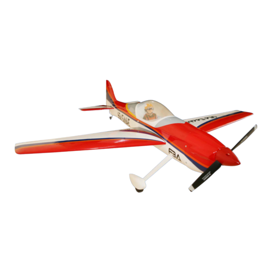
"Graphics and specifications may change without notice".
Specifications:
Wing span -----------------------------49.2.in (125cm).
Wing area -----------------415.4sq.in (26.8sq dm).
Weight ------------------------5.1-5.5lbs (2.3-2.5kg).
Length ------------------------------50.7in (128.7cm).
Engine ---------------------------0.46cu.in -2-stroke.
.
0.62cu.in -4-stroke
Radio -------------------4 channels with 5 servos.
Electric conversion: optional
Advertisement
Table of Contents

Related Manuals for Seagull Models SEA EAGLE


Summary of Contents for Seagull Models SEA EAGLE
- Page 1 MS:190 ASSEMBLY MANUAL “Graphics and specifications may change without notice”. Specifications: Wing span -----------------------------49.2.in (125cm). Wing area -----------------415.4sq.in (26.8sq dm). Weight ------------------------5.1-5.5lbs (2.3-2.5kg). Length ------------------------------50.7in (128.7cm). Engine ---------------------------0.46cu.in -2-stroke. 0.62cu.in -4-stroke Radio -------------------4 channels with 5 servos. Electric conversion: optional...
-
Page 2: Kit Contents
. Flying the SEA EAGLE is simply a joy. This instruction manual is designed to help you build a great flying aeroplane. Please read this manual thoroughly before starting assembly of your SEA EAGLE . Use the parts listing below to identify all parts. -
Page 3: Hinging The Aileron
www.seagullmodels.com HINGING THE AILERON . CONTENTS.TS Note: The control surfaces, including the Fuselage ailerons, elevators, and rudder, are Wing Set Tail Set prehinged with hinges installed, but Cowling the hinges are not glued in place. It Canopy is imperative that you properly Main Landing Gear adhere the hinges in place per the Wing Tube... - Page 4 Instruction Manual. SEA EAGLE Hinge. 4) Deflect the aileron and completely saturate each hinge with thin C/A glue. The 5) Turn the wing panel over and deflect the ailerons front surface should lightly contact the aileron in the opposite direction from the wing during this procedure.
-
Page 5: Hinging The Elevator
www.seagullmodels.com HINGING THE ELEVATOR. INSTALL ELEVATOR CONTROL HORN. Glue the rudder hinges in place using the Install the elevator control horn using the same techniques used to hinge the ailerons. same method as same as the aileron control horns. HINGING THE RUDDER. Fiberglass control horn Glue the rudder hinges in place using the same techniques used to hinge the ailerons. -
Page 6: Engine Mount Installation
Instruction Manual. SEA EAGLE ENGINE MOUNT INSTALLATION. 1) Locate the items necessary to install the engine mount included with your model. . 4x30mm. 2) Use four 4x30mm head bolts and four 4mm washers to attach the engine mount rails to the firewall. -
Page 7: Installing The Fuselage Servos
www.seagullmodels.com You should mark which tube is the vent Blow through one of the lines to en- and which is the fuel pickup when you attach sure the fuel lines have not become kinked fuel tubing to the tubes in the stopper. Once inside the fuel tank compartment. -
Page 8: Installing The Switch
Instruction Manual. SEA EAGLE 2) Use a pin drill and 2mm drill bit to drill a INSTALLING THE SWITCH. small indentation in the mount for the engine mounting screw. Install the switch into the precut hole in the side, in the fuselage. - Page 9 www.seagullmodels.com 7) Slide the throttle pushrod wire into the tube. WHEEL AND WHEEL PANTS Position the engine between the mounts. Use INSTALLATION. four M3x25mm machine screws to secure the engine to the mount as shown. 1) Locate the items neccessary to install the wheel and wheel pants to the landing gear Pushrod wire.
- Page 10 Instruction Manual. SEA EAGLE wheel collar. wheel. Washer. nut. Axle. wheel Pant. Locker glue. 5) Place the wheel assembly in the wheel pants. The threaded portion of the axle will fit the notch of the wheel pant as shown. 6) Slide the threaded end of the axle through the hole in the bottom of the landing gear leg.
- Page 11 www.seagullmodels.com Thread locker glue. Trim and cut. Trim and cut. COWLING. Because of the size of the cowl, it may be nec- essary to use a needle valve extension for the 1)Slide the fiberglass cowl over the engine high speed needle valve. Make this out of suf- and line up the back edge of the cowl with the ficient length 1.5mm wire and install it into the marks you made on the fuselage then trim and...
- Page 12 Instruction Manual. SEA EAGLE Needle valve. Recommendation EP parts as shown (not included with your model) - Model size: .46 size models - Propeller: 12x6 ~ 13x6 - ESC: 60A - Lipo Batteries: 4 cell 3200mA 2) Attach the electric motor box to the firewall suitable with the cross lines drawn on the electric motor box and firewall.
-
Page 13: Installing The Spinner
www.seagullmodels.com M3x12mm. Electric motor. 4mm. Epoxy. 110mm. 5) Attach the speed control to the side of the motor box using two-sided tape and tie wraps. Connect the appropriate leads from the speed control to the motor. Make sure the leads will not interfere with the operation of the motor. -
Page 14: Installing The Aileron - Flap Servos
Instruction Manual. SEA EAGLE The propeller should not touch any part of the spinner cone. If it does, use a sharp modeling knife and carefully trim away the spinner cone where the propeller comes in contact with it. 3) Use drill bit in a pin vise to drill the mouting holes in the blocks. - Page 15 www.seagullmodels.com 7) Apply 1-2 drops of thin C/A to each of the mounting tabs. Allow the C/A to cure without using accelerator. 9) Set the aileron hatch in place and use a 8) A string has been provided in the wing to Phillips screw driver to install it with four wood pull the aileron lead through to the wing root.
-
Page 16: Installing The Horizontal Stabilizer
Instruction Manual. SEA EAGLE 1) Mark the control wire where it crosses the INSTALLING THE HORIZONTAL STABILIZER. servo arm hole. 1) Using a ruler and a pen, locate the centerline of the horizontal stabilizer, at the trail- ing edge, and place a mark. Use a triangle and extend this mark, from back to front, Bend at the mark. - Page 17 www.seagullmodels.com 7) When you are sure that everything is 4) With the stabilizer held firmly in place, aligned correctly, mix up a generous amount use a pen and draw lines onto the stabilizer of 30 Minute Epoxy. Apply a thin layer to the where it and the fuselage sides meet.
- Page 18 Instruction Manual. SEA EAGLE 4) When you are sure that everything is aligned correctly, mix up a generous amount of Fill epoxy. Flash 30 Minute Epoxy. Apply a thin layer to the mounting slot and to bottom of the vertical sta- bilizer mounting area.
- Page 19 www.seagullmodels.com Elevator fiberglass control horn. M3 x 12mm. 3) Thread one clevis and M2 lock nut on to each elevator control rod. Thread the horns on until they are flush with the ends of the con- trol rods. 4) Elevator and rudder pushrods assembly as pictures below.
- Page 20 Instruction Manual. SEA EAGLE RUDDER PUSHROD HORN INSTALLATION. M2 lock nut . M2 clevis. 8mm. Elevator fiberglass control horn. Rudder fiberglass control horn. Pen. Elevator pushrod. Rudder pushrod. 8mm. Wire keeper. Pen.
-
Page 21: Apply The Decals
www.seagullmodels.com 3) Position the pilot figure on the canopy floor as show. Locate the oval shaped on the canopy floor and remove the covering. Use epoxy to glue this into the base of the pilot figure and glue the cockpit panel in place with C/A glue, please see pictures as shown. - Page 22 Instruction Manual. SEA EAGLE 2) If all the decals are not precut, please use Insert two wing panels as pictures below. scissors or a sharp hobby knife to cut the decals from the sheet. Please be certain the model is clean and free from oily fingerprints and dust.
-
Page 23: Control Throws
www.seagullmodels.com BALANCING. 100mm. 1) It is critical that your airplane be balanced correctly. Improper balance will cause your plane to lose control and crash. THE CENTER OF GRAVITY IS LOCATED 100 MM BACK FROM THE LEADING EDGE OF THE WING AT THE WING ROOT. 2) Mount the wing to the fuselage. -
Page 24: Flight Preparation
2) Check every bolt and every glue joint A) Plug in your radio system per the in the SEA EAGLE to ensure that everything manufacturer's instructions and turn every- is tight and well bonded. thing on.
Need help?
Do you have a question about the SEA EAGLE and is the answer not in the manual?
Questions and answers