Table of Contents
Advertisement
Quick Links
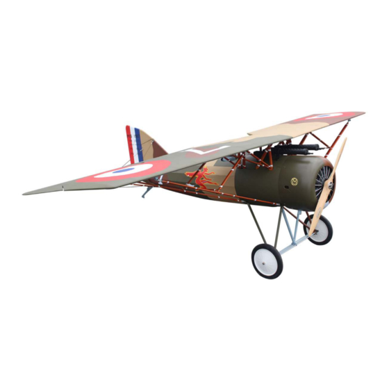
Code : SEA 358
ASSEMBLY MANUAL
Speciications:
Wingspan------ 103 in (262 cm).
Wing area------ 1839.9 sq.ins (118.7sq.dm).
Weight---------- 25.3-26.9 lbs (11.5-12.2 kg).
Length---------- 66.7 in (169.3 cm).
Engine---------- 50cc-62 cc
Radio----------- 5 channels with 6 servos
Motor 360/ 3000watt/ ESC 160A-200A/ Lipo 12s;
Electric propeller 24x10 - 26x8
ITEM CODE : SEA 358
1
Advertisement
Table of Contents

Subscribe to Our Youtube Channel
Related Manuals for Seagull Models SEA 358


Summary of Contents for Seagull Models SEA 358
- Page 1 Wing area------ 1839.9 sq.ins (118.7sq.dm). Weight---------- 25.3-26.9 lbs (11.5-12.2 kg). Length---------- 66.7 in (169.3 cm). Engine---------- 50cc-62 cc Radio----------- 5 channels with 6 servos Motor 360/ 3000watt/ ESC 160A-200A/ Lipo 12s; Electric propeller 24x10 - 26x8 ITEM CODE : SEA 358...
-
Page 2: Kit Contents
Instruction Manual. 1/3 ScaleMorane Saulnier AI INTRODUCTION hank you for choosing the 1/3 Scale Morane Saulnier AI ARTF by SG MODELS . he 1/3 Scale Morane Saulnier AI was designed with the intermediate/advanced sport lyer in mind. It is a semi scale airplane which is easy to ly and quick to assemble. he air- frame is conventionally built using balsa, plywood to make it stronger than the aver- age ARTF, yet the design allows the aeroplane to be kept light. -
Page 3: Hinging The Aileron
KIT CONTENTS HINGING THE AILERON SEA 358 1/3 Scale Morane Saulnier AI Note : he control surfaces, including the ailer- ons, elevators, and rudder, are prehinged with 1. Fuselage hinges installed, but the hinges are not glued in 2. Wing set (3) place. - Page 4 Instruction Manual. 1/3 ScaleMorane Saulnier AI Delect the aileron and completely saturate each hinge with thin C/A glue. he ailerons front surface should lightly contact the wing during this procedure. Ideally, when the hinges are glued in place, a 1/64” gap or less will be maintained throughout the lengh of the aileron to the wing panel hinge line.
- Page 5 Place low-tack tape 1/32 inch (1mm) INSTALL THE AILERONS from the control horn slot. his will pre- CONTROL HORN vent epoxy from getting on the control surface when the control horns are glued Locate the aileron and lap control horns. in place.
-
Page 6: Installing The Aileron Servos
Instruction Manual. 1/3 ScaleMorane Saulnier AI Epoxy Before the epoxy fully cures, remove the tape from around the control horn. Minimum servo spec. Torque : 6.0V: 157.00 oz-in (11.31 kg-cm) his will allow the epoxy to low around 7.4V: 179.00 oz-in (12.89 kg-cm) the control horn, creating a small ilet between the control horn and surface for a iished look and secure bond. - Page 7 Apply 1-2 drops of thin C/A to each of the mounting tabs. Allow the C/A to cure without using accelerator. C/A glue Apply 2-3 drops of thin C/A to each of the mounting holes. Allow the C/A to cure without using accelerator. Remove the string from the wing at the servo location and use the tape to attach it to the servo extension lead.
-
Page 8: Aileron Pushrod Installation
Instruction Manual. 1/3 ScaleMorane Saulnier AI Set the aileron hatch in place and use a 75mm Phillips screw driver to install it with four wood screws. M2.5x10mm M3 clevis M3 lock nut INSTALLING THE FUSELAGE SERVOS Because the size of servos difer, you may need to adjust the size of the precut opening in the mount. - Page 9 Elevator servo Rudder servo Elevator servo Elevator servo arm Rudder servo arm Switch Elevator servo arm INSTALLING THE MAIN LANDING GEAR TO FUSELAGE Minimum servo spec. Please study images below. Torque : 6.0V: 157.00 oz-in (11.31 kg-cm) 7.4V: 179.00 oz-in (12.89 kg-cm) INSTALLING THE ENGINE SWITCH Insert the switch into the pre-cut hole in the fuselage...
- Page 10 Instruction Manual. 1/3 ScaleMorane Saulnier AI head locker glue M4x20mm...
- Page 12 Instruction Manual. 1/3 ScaleMorane Saulnier AI 3x4mm 3x4mm 3x4mm 3x4mm...
- Page 13 Loop the cord over the forward axle support, under the shock cord collar, then over the rear axle support. Tie the shock cord to the rear axle support. Leave 1/2-inch (13mm) of shock cord outside the knot so the opposite end of the shock cord can be secure to it.
- Page 14 Instruction Manual. 1/3 ScaleMorane Saulnier AI Use a tie wrap to secure the shock cord ends together. Use hemostats to hold the shock cord while installing the tie wrap. Cut the excess of the tie wrap so the landing gear wing cover can be installed. When the shock cord is installed, it will it inside the landing gear wing and will not interfere with the installation of the...
-
Page 15: Installing The Stopper Assembly
INSTALLING THE STOPPER ASSEMBLY Using a modeling knife, carefully cut of the rear portion of one of the 3 nylon tubes leaving 1/2” protruding from the rear of the stopper. his will be the fuel pick up tube. Using a modeling knife, cut one length of silicon fuel line. -
Page 16: Fuel Tank Installation
Instruction Manual. 1/3 ScaleMorane Saulnier AI Test it the stopper assembly into the tank. It may be necessary to remove some of the lashing around the tank opening using a modeling knife. If lashing is present, make sure none falls into the tank. With the stopper assembly in place, the weighted pick-up should rest away from the rear of the tank and move freely inside the... -
Page 17: Mounting The Engine
MOUNTING THE ENGINE Please study images below. Locate the engine mounting in position on the irewall. Use a 2.5mm drill bit to drill the holes necessary to mount your particular motor choice. M4 Nylon 2.5mm Vent tube Fuel pick up tube Fuel ill tube Connect the lines from the tank to the engine and muler. - Page 18 Instruction Manual. 1/3 ScaleMorane Saulnier AI Position the engine with the drive washer (197mm) forward of the irewall. 197mm...
- Page 19 Ignition Module Epoxy Attach the muler to the engine using the hardware included with the muler. Use epoxy glue to attach the push base to the inside of the fuselage and propeller.
- Page 20 Instruction Manual. 1/3 ScaleMorane Saulnier AI COWLING Please study images below. Epoxy Reinstall the servo horn by sliding the connector over the pushrod wire. Cent- er the throttle stick and trim and install the servo horn perpendiular to the servo center line.
- Page 21 Epoxy...
- Page 22 Instruction Manual. 1/3 ScaleMorane Saulnier AI Use a drill and drill bit to drill the holes for the cowl mounting screws. Make sure the cowl position is correct before drilling each hole. Install the muler and muler extension onto the engine and make the cutout in the cowl for muler clearance.
- Page 23 ELECTRIC POWER CONVERSION Locate the items neccessary to install the electric power conversion included with your model. Recommend the items necessary to install the electric power conversion parts included with your model. - Motor: 360 - 6000 Watts - Propeller: 24x10 ~ 26x8 - ESC: 160A - 200A - 12S Lipo Locate the engine mounting in position...
- Page 24 Instruction Manual. 1/3 ScaleMorane Saulnier AI hen, use 5mm drill bit to enlarge the holes on the electric motor box. Attach the motor mount to the front of the electric motor box using four 5mm blind nut, four M5x20mm hex head bolts to secure the motor.
- Page 25 Epoxy Attach the speed control to the side of the motor box using two-sided tape and tie wraps. Connect the appropriate leads from the speed control to the mo- tor. Make sure the leads will not interfere Battery with the operation of the motor. 197mm Battery...
-
Page 26: Installing The Spinner
Instruction Manual. 1/3 ScaleMorane Saulnier AI INSTALL ELEVATOR CONTROL HORN INSTALLING THE SPINNER Install the spinner backplate, propeller and spinner cone. Fiberglass control horn he propeller should not touch any part of the spinner cone. If it does, use a sharp modeling knife and carefully trim away the spinner cone where the propel- ler comes in contact with it. -
Page 27: Elevator And Stabilizer Installation
Remove the stabilizer. Using the lines you just drew as a guide, carefully remove the covering from between them using a modeling knife. ELEVATOR AND STABILIZER INSTALLATION When cutting through the covering to remove it, cut with only enough pressure to only cut through the covering itself. - Page 28 Instruction Manual. 1/3 ScaleMorane Saulnier AI Slide the stabilizer partially into the Once the alignment of the stabilizer fuselage so the wood at the center is ex- has been veriid, use a paper towel and posed. Mix 1/2 ounce (15ml) of 30-min- isopropyl alcohol to remove any excess ute epoxy.
- Page 29 Flex the elevator slightly, making sure Fit the elevator so the leading edge is to keep the gap between the elevator and tightly against the trailing edge of the stabilizer as narrow as possible. Saturate stabilizer. each of the hinges using thin CA. Apply CA to the top of the hinges.
-
Page 30: Installing Vertical Stabilizer
Instruction Manual. 1/3 ScaleMorane Saulnier AI INSTALL RUDDER CONTROL HORN INSTALLING VERTICAL STABILIZER Repeat steps to install the rudder control horn as same as steps done for ailerons. Fiberglass control horn C/A glue Epoxy... -
Page 31: Installation
ELEVATOR PUSHROD M3 clevis M3 lock nut INSTALLATION Install the elevator control horn using the same method as with the aileron control horns. Position the elevator control horn on the both side of elevator. hread one clevis and M2 lock nut on to each elevator control rod. - Page 32 Instruction Manual. 1/3 ScaleMorane Saulnier AI...
-
Page 33: Mounting The Tail Wheel
MOUNTING THE TAIL WHEEL Locate items necessary to install tail wheel. M3x20mm M3x15mm... - Page 34 Instruction Manual. 1/3 ScaleMorane Saulnier AI Make sure you have loctite glue or it will come loose. Loctite...
- Page 35 INSTALL BRACING WIRE AND METAL BRACKET AT THE TAIL TOP VIEW. 211.77mm...
- Page 36 Instruction Manual. 1/3 ScaleMorane Saulnier AI M3x15mm M3x20mm BOTTOM VIEW.
- Page 37 Loctite M3x15mm...
- Page 38 Instruction Manual. 1/3 ScaleMorane Saulnier AI head locker glue INSTALL GUN Parts requirement. Please study images below.
- Page 39 M3x25mm M3x25mm...
-
Page 40: Cabane Strut Installation
Instruction Manual. 1/3 ScaleMorane Saulnier AI CABANE STRUT INSTALLATION Loacte the items for this section of the manual. Decor for the strut. - Page 41 Get the middle number 1 strut and in- stall it on the fuselage. 216mm 156mm Setting the number 2 with the number 1.
- Page 42 Instruction Manual. 1/3 ScaleMorane Saulnier AI Get the middle number 3 strut and in- stall it on the fuselage. 192mm M3x15mm...
- Page 43 M3x15mm Get the middle number 4 strut and in- stall it on the fuselage.
- Page 44 Instruction Manual. 1/3 ScaleMorane Saulnier AI 225mm M3x15mm Setting the number 5 with the number 1.
- Page 45 M3x15mm head locker glue...
- Page 46 Instruction Manual. 1/3 ScaleMorane Saulnier AI M3x12mm M3x12mm head locker glue...
- Page 47 M3x15mm...
- Page 48 Instruction Manual. 1/3 ScaleMorane Saulnier AI M3x12mm Take the number 6 strut in the middle and attach it to the fuselage.connect from 2 to 5. 293mm...
- Page 49 M3x12mm...
- Page 50 Instruction Manual. 1/3 ScaleMorane Saulnier AI M3x12mm Epoxy INSTALLATION COCKPIT Locate items necessary to install.
- Page 52 Instruction Manual. 1/3 ScaleMorane Saulnier AI INSTALLATION PILOT AND CANOPY Locate items necessary to install. Epoxy Epoxy...
- Page 53 ATTACHMENT WING- FUSELAGE M4x12mm Attach the aluminium tube into fuselage. Wing tube M4x12mm...
- Page 54 Instruction Manual. 1/3 ScaleMorane Saulnier AI INSTALLATION WING STRUTS Locate the items for this section of the manual. M3x12mm M3x12mm 795mm...
- Page 55 M3x15mm...
- Page 56 Instruction Manual. 1/3 ScaleMorane Saulnier AI...
- Page 57 250mm M2x12mm 269mm...
- Page 58 Instruction Manual. 1/3 ScaleMorane Saulnier AI M3x12mm 262mm...
- Page 60 Instruction Manual. 1/3 ScaleMorane Saulnier AI *If possible, irst attempt to balance the APPLY THE DECALS model by changing the position of the 1) If all the decals are precut and ready to receiver battery and receiver. If you are stick.
-
Page 61: Control Throws
150-170mm CONTROL THROWS Ailerons: Rudder: High Rate : High Rate : Up : 50 mm Right : 60 mm Down : 50 mm Let : 60 mm Low Rate : Low Rate : Up : 30 mm Right : 40 mm Down : 30 mm Let : 40 mm Elevator:... - Page 62 Instruction Manual. 1/3 ScaleMorane Saulnier AI 35-50mm 35-50mm 40-60mm Fuselage 40-60mm 30-50mm Wing 30-50mm...
-
Page 63: Flight Preparation
FLIGHT PREPARATION PREFLIGHT CHECK 1) Completely charge your trans- Check the operation and direction mitter and receiver batteries before of the elevator, rudder, ailerons and your irst day of lying. throttle. 2) Check every bolt and every glue A) Plug in your radio system per the joint in the 1/3 ScaleMorane Saulnier manufacturer’s instructions and turn everything on. - Page 64 Instruction Manual. 1/3 ScaleMorane Saulnier AI If you have any queries, or are interested in our products, please feel free to contact us Factory : 12/101A - Hamlet 4 - Le Van Khuong Street - Dong hanh Ward - Hoc Mon District - Ho Chi Minh City - Viet Nam. Oice : 62/8 Ngo Tat To Street - Ward 19 - Binh hanh District - Ho Chi Minh City - Viet Nam Phone : 848 - 86622289 or 848- 36018777...
Need help?
Do you have a question about the SEA 358 and is the answer not in the manual?
Questions and answers