Table of Contents
Advertisement
Quick Links
A S S E M B L Y M A N U A L
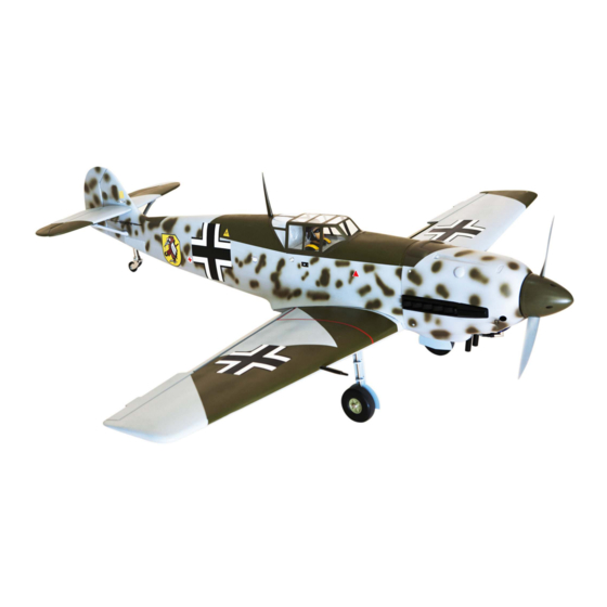
MESSERSCHMITT
- Bf 109E 60
Code: SEA278
" Graphics and specifications may change without notice ".
Specifications:
Wingspan---------------64.0 in (163 cm).
Wing area---------------765.7 sq.in ( 49.4sq.dm).
Weight-------------------11.0 lbs ( 5.0kg).
Length-------------------61.4 in (156 cm).
Engine-------------------0.91 2-stroke
....................................1.25 4-stroke
....................................20cc gasoline
Radio--------------------7 channels with 9 servos.
1
Advertisement
Table of Contents

Related Manuals for Seagull Models SEA278


Summary of Contents for Seagull Models SEA278
- Page 1 A S S E M B L Y M A N U A L MESSERSCHMITT - Bf 109E 60 Code: SEA278 “ Graphics and specifications may change without notice ”. Specifications: Wingspan---------------64.0 in (163 cm). Wing area---------------765.7 sq.in ( 49.4sq.dm).
-
Page 2: Kit Contents
Messerschmitt Bf 109E 60 Instruction Manual. INTRODUCTION. Thank you for choosing the MESSERSCHMITT Bf109E60 ARF by SG MODELS. The MESS- ERSCHMITT Bf109E60 was designed with the intermediate/advanced sport flyer in mind. It is a semi scale airplane which is easy to fly and quick to assemble. The airframe is conven- tionally built using balsa, plywood to make it stronger than the average ARF, yet the design allows the aeroplane to be kept light. -
Page 3: Additional Items Required
HINGING THE FLAP. KIT CONTENTS. SEA278 MESSERSCHMITT Bf109E 60 1. Fuselage 2. Wing set 3. Tail set 4. Canopy 5. Cowling 6. Pilot 7. Aluminum wing tube 2x10mm ADDITIONAL ITEMS REQUIRED. 0.91 2-stroke � 1.25 4-stroke � 20cc gasoline engine. -
Page 4: Hinging The Aileron
Messerschmitt Bf 109E 60 Instruction Manual. Hinge. 3) Slide the wing panel on the aileron until there is only a slight gap. The hinge is now centered on the wing panel and aileron. Re- move the T-pins and snug the aileron against the wing panel. - Page 5 INSTALL THE AILERONS CONTROL HORN. Thin CA. Locate the aileron and flap control horns. The taller control horn is used for the ailer- ons, and the shorter horn for the flaps. 5) Turn the wing panel over and deflect the aileron in the opposite direction from the opposite side.
-
Page 6: Wing Assembly
Messerschmitt Bf 109E 60 Instruction Manual. Note : to be convenience for trans- ports ,you don’t need to do this steps. Epoxy. INSTALLING THE AILERON SERVOS. Flap control horn. WING ASSEMBLY. Attach the aluminum tube into wing. Because the size of servos differ, you may need to adjust the size of the precut opening in the mount. -
Page 7: Aileron Pushrod Installation
9) Set the aileron servo in place and use a Phillips screw driver to install it with four wood screws. 2x10mm AILERON PUSHROD INSTALLATION. Please see below pictures. 45mm... - Page 8 Messerschmitt Bf 109E 60 Instruction Manual. M3 lock nut. M3 clevis. STANDARD FIXED LANDING GEAR. 1) Locate the items necessary to install retractable landing gear as shown. INSTALLING THE FLAP SERVO. Repeat the procedure for the flap servo. INSTALLING THE FLAP PUSHROD. Repeat the procedure for the aileron pushrod.
- Page 9 Mark. Drill. 3.5x20mm 2) Install servo for Retractable landing gear. Epoxy 40mm M3 clevis. M3 lock nut.
- Page 10 Messerschmitt Bf 109E 60 Instruction Manual. 4) Slide the wheel on the axle, then secure it using the wheel collar and M3x4 socket head cap screws. Collar. M3x4mm 3) Secure the landing gear doors to the landing gear struts. Collar. Epoxy M3x4mm Epoxy...
-
Page 11: Optional Retractable Landing Gear
OPTIONAL RETRACTABLE LANDING GEAR. Electric retractable landing gear is not included in this kit, however it is a very popular add-on as optional. If you want to use retracts in your Messerchsmitt we recommend that you buy a good set of electric retracts as the Himark AM05 Main Gear shown as below. -
Page 12: Installing The Fuselage Servos
Messerschmitt Bf 109E 60 Instruction Manual. Drill. Collar. 3.5x20mm M3x4mm Secure the landing gear doors to the landing gear struts. INSTALLING THE FUSELAGE SERVOS. Epoxy Because the size of servos differ, you may need to adjust the size of the precut opening in the mount. - Page 13 1) Install the rubber grommets and brass collets onto all servos. Test fit the servos 3/32” Hole. into the servo mounts. 2) Secure the servos with the screws pro- vided with your radio system. Elevator servo. Throttle servo. Trim and cut. Rudder servo.
-
Page 14: Installing The Stopper Assembly
Messerschmitt Bf 109E 60 Instruction Manual. 3) Carefully bend the second nylon tube up INSTALLING THE STOPPER at a 45º angle. This tube is the vent tube. ASSEMBLY. 4) Test fit the stopper assembly into the tank. 1) Using a modeling knife, carefully cut It may be necessary to remove some of the off the rear portion of one of the 3 nylon flashing around the tank opening using a... -
Page 15: Engine Mount Installation
Vent tube. Epoxy Fuel fill tube. Fuel pick up tube. 8) Connect the lines from the tank to the en- gine and muffler. The vent line will connect to the muffler and the line from the clunk to the carburetor. Blow through one of the lines to ensure the fuel lines have not become kinked inside the fuel tank compartment. -
Page 16: Mounting The Engine
Messerschmitt Bf 109E 60 Instruction Manual. 2) Use four 4x30mm head bolts and four 4mm washers to attach the engine mount rails to the firewall. Tighten the screws . Make sure to use threadlock on the screws to help prevent them from vibrating loose. Thread locker glue. - Page 17 4) On the fire wall has the location for the throttle pusshrod tube (pre-drill). 5) Slide the pushrod tube in the firewall and guide it through the fuel tank mount. Use medium C/A to glue the tube to the firewall and the fuel tank mount. 6) Connect the Z-bend in the 500mm throttle pushrod to the outer hole of the carburetor arm.
- Page 18 Messerschmitt Bf 109E 60 Instruction Manual. 3x10mm Because of the size of the cowl, it may be nec- COWLING. essary to use a needle valve extension for the high speed needle valve. Make this out of suf- 1) Tape the cowl to the fuselage using ficient length 1.5mm wire and install it into low-tack tape.
- Page 19 ELECTRIC POWER CONVERSION. 1) Locate the items neccessary to install the electric power conversion included with your model. M4x20mm 4) Attach the motor to the front of the electric motor box using four 4mm blind nut, four M4x20mm hex head bolts to se- cure the motor.
- Page 20 Messerschmitt Bf 109E 60 Instruction Manual. Balsa stick. Epoxy 6) Attach the speed control to the side of the motor box using two-sided tape and tie wraps. Connect the appropriate leads from the speed control to the mo- tor. Make sure the leads will not interfere with the operation of the motor.
-
Page 21: Installing The Spinner
INSTALLING THE SPINNER. 3x12mm The propeller should not touch any part of the spinner cone. If it does, use a sharp modeling knife and carefully trim Battery. away the spinner cone where the propel- ler comes in contact with it. Open the air exit hole. -
Page 22: Hinging The Elevator
Messerschmitt Bf 109E 60 Instruction Manual. HINGING THE ELEVATOR. Glue the elevator hinges in place using the same techniques used to hinge the ai- lerons. INSTALL ELEVATOR CONTROL HORN. Epoxy Fiberglass control horn Epoxy Epoxy. -
Page 23: Installing The Horizontal Stabilizer
Elevator fiberglass control horn. Epoxy. 4) With the stabilizer held firmly in place, use a pen and draw lines onto the stabi- lizer where it and the fuselage sides meet. INSTALLING THE HORIZONTAL Do this on both the right and left sides STABILIZER. -
Page 24: Hinging The Rudder
Messerschmitt Bf 109E 60 Instruction Manual. Epoxy 7) When you are sure that everything is aligned correctly, mix up a generous amount of 30 Minute Epoxy. Apply a thin layer to the top and bottom of the stabi- INSTALL RUDDER CONTROL HORN. lizer mounting area and to the stabilizer mounting platform sides in the fuselage. -
Page 25: Installing Vertical Stabilizer
INSTALLING VERTICAL STABILIZER Hinge slot. 3) While holding the vertical stabilizer firmly in place, use a pen and draw a line on eachside of the vertical stabilizer where it meets the top of the fuselage. 1) Using a modeling knife, remove the covering from over the precut hinge slot cut into the lower rear portion of the fu- selage. -
Page 26: Elevator Pushrod Installation
Messerschmitt Bf 109E 60 Instruction Manual. 5) When you are sure that everything is 3) Thread one clevis and M2 lock nut on aligned correctly, mix up a generous to each elevator control rod. Thread the amount of Flash 30 Minute Epoxy. Ap- horns on until they are flush with the ply a thin layer to the mounting slot ends of the control rods. -
Page 27: Rudder Pushrod Installation
RUDDER PUSHROD INSTALLATION. M3x4mm Repeat steps as same as steps done for elevator. Cut. M2 clevis. M2 lock nut. 825mm 150mm M2 lock nut. M2 clevis. Elevator pushrod. Rudder pushrod. -
Page 28: Mounting The Tail Wheel
Messerschmitt Bf 109E 60 Instruction Manual. MOUNTING THE TAIL WHEEL. - Page 29 715mm M2 lock nut. M2 clevis. TAIL STRUTS. Epoxy.
- Page 30 Messerschmitt Bf 109E 60 Instruction Manual. 3x15mm 3x15mm...
- Page 31 Epoxy. 85mm INSTALLATION PILOT AND CANOPY. 4) Position the canopy onto the fuselage. Trace around the canopy and onto the fu- 1) Locate items necessary to install pilot, selage using a felt-tipped pen. Carefully seats. cut and remove covering material from the fuselage where the canopy makes contact, exposing the bare wood.
-
Page 32: Apply The Decals
Messerschmitt Bf 109E 60 Instruction Manual. 3) Route the antenna in the antenna tube APPLY THE DECALS. inside the fuselage and secure it to the bottom of fuselage using a plastic tape. 1) If all the decals are precut and ready to stick. - Page 33 ATTACHMENT WING- FUSELAGE. Epoxy BALANCING. 1) It is critical that your airplane be balanced correctly. Improper balance will cause your plane to lose control and crash. THE CENTER OF GRAV- ITY IS LOCATED 135MM BACK FROM THE LEADING EDGE OF THE WING AT THE WING ROOT.
-
Page 34: Control Throws
Messerschmitt Bf 109E 60 Instruction Manual. Accurately mark the balance point on the top of the wing on both sides of the fuselage. The balance point is located 135mm back from the leading edge of the 135mm wing at the wing root. This is the balance point at which your model should balance for your first flights. -
Page 36: Flight Preparation
Messerschmitt Bf 109E 60 Instruction Manual. FLIGHT PREPARATION. PREFLIGHT CHECK. Check the operation and direction 1) Completely charge your trans- of the elevator, rudder, ailerons and mitter and receiver batteries before throttle. your first day of flying. A) Plug in your radio system per the 2) Check every bolt and every glue manufacturer’s instructions and turn joint in the MESSERSCHMITT to...
Need help?
Do you have a question about the SEA278 and is the answer not in the manual?
Questions and answers