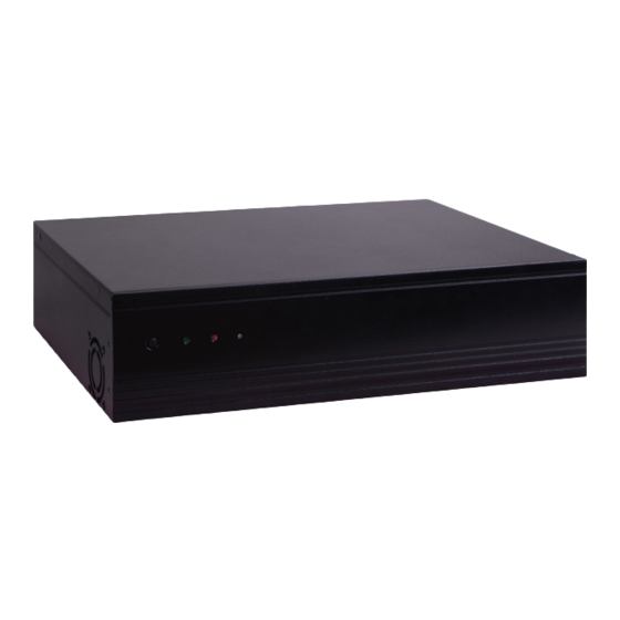
Summary of Contents for DFI DT122-SD
-
Page 1: Installation Guide
DT122-SD Installation Guide Package Contents • 1 DT122-SD system unit • 1 HDD drive bay kit • 1 Quick Installation Guide • 1 CD disk includes: - Drivers/Manual Optional Items • Power Cord www.dfi .com... - Page 2 Install a 2.5" or 3.5" SATA Drive lnstall a 2.5" SATA Drive 1. Remove the 4 mounting screws that secure the drive bay to the system. Mounting screw Drive bay Mounting screw 2. Align the mounting holes on the SATA drive with the mounting holes on the HDD bracket and use the mounting screws provided in the drive bay kit to secure the drive in place.
- Page 3 3. Use the provided mounting screws to attach the HDD bracket to the drive bay. Mounting screws Drive bay (bottom side) Mounting holes 4. Place the SATA drive bay back in the chassis and install the SATA drive bay using the mounting screws you removed in step 1.
- Page 4 5. Connect the SATA data and power cable to the SATA drive. SATA power/data cable SATA connector...
- Page 5 lnstall a 3.5" SATA Drive 1. Remove the 4 mounting screws that secure the drive bay to the system. Mounting screw Drive bay Mounting screw 2. Insert the spacers provided in HDD drive bay kit to the anti-shock bumper. Spacer Spacer Drive bay...
- Page 6 3. Align the mounting holes on the SATA drive with the mounting holes on the drive bay; then use the provided mounting screws to install the SATA drive on the drive bay. Mounting screw Mounting screw Drive bay 4. Place the drive bay back in the chassis and install the drive bay using the mounting screws you removed in step 1.
-
Page 7: Board Layout And Jumper Settings
Board Layout and Jumper Settings Mini PCIe Select (JP1) USB 2.0 LVDS Inverter Power (JP2) (JP7) LVDS Power Select USB 11-12 (Only for COM1 RS232/Power (JP6) Select SD100-Q170) COM2 RS232/Power (JP8) USB 7-8 Select SATA 3 SATA 0 SATA 2 PS/2 LVDS LCD Panel (JP7)


Need help?
Do you have a question about the DT122-SD and is the answer not in the manual?
Questions and answers