Table of Contents
Advertisement
Quick Links
Download this manual
See also:
Installation Manual
Advertisement
Table of Contents

Related Manuals for DFI DT122-HR


Summary of Contents for DFI DT122-HR
- Page 1 DT122-HR Desktop Box PC User’s Manual A26600313 Chapter 1 Introduction www.dfi .com...
-
Page 2: Copyright
Copyright FCC and DOC Statement on Class B This equipment has been tested and found to comply with the limits for a Class B digital This publication contains information that is protected by copyright. No part of it may be reproduced in any device, pursuant to Part 15 of the FCC rules. -
Page 3: Table Of Contents
....................... 6 Key Features CompactFlash Socket ................. 31 ....................6 Specifications Expansion Slots ..................32 ....................7 Getting to Know the DT122-HR Battery ..................... 33 ............. 8 Mechanical Dimensions ................9 Chapter 6 - Mounting Options Motherboad Dimensions .............. 34 ................ -
Page 4: About This Manual
About this Manual Static Electricity Precautions An electronic file of this manual is included in the CD. To view the user’s manual in the CD, in- It is quite easy to inadvertently damage your PC, system board, components or devices even sert the CD into a CD-ROM drive. -
Page 5: About The Package
• Unplug the power cord before removing the system chassis cover for installation or servic- ing. After installation or servicing, cover the system chassis before plugging the power cord. • 1 DT122-HR system unit • 1 HDD drive bay kit •... -
Page 6: Chapter 1 - Introduction
Chapter 1 Chapter 1 - Introduction Key Features Overview DT122-HR ® PROCESSOR 3rd/2nd Generation Intel Core processors (under 45W) ® CHIPSET Intel QM67 2 LAN ports 2 COM ports DISPLAYS DVI-I (DVI-D Signal), 1 VGA 4 Type A USB 2.0/1.1 ports 2 Type A USB 2.0/1.1 ports (optional) -
Page 7: Specifications
Chapter 1 Specifications Processor System • Processors: I/O Ports • Front Panel - 1 Power button - 3rd Generation Intel ® Core processors (22nm process technology) : Intel ® Core™ i7-3610QE (6M Cache, up to 3.3 GHz); 45W - 1 Reset button : Intel ®... -
Page 8: Getting To Know The Dt122-Hr
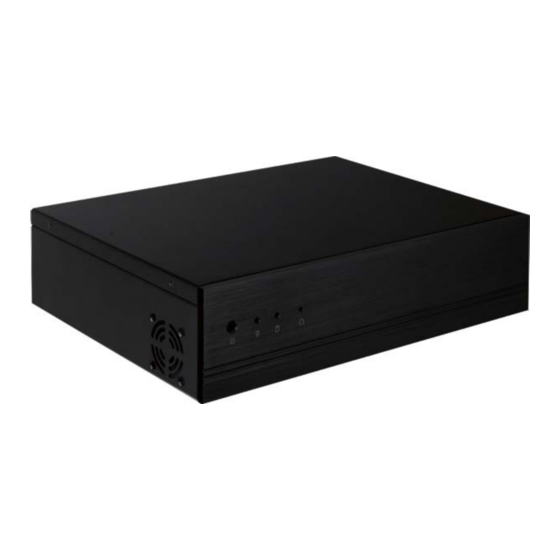
Chapter 1 Getting to Know the DT122-HR Front View Rear View PS/2 Mouse Reset Button Expansion slot COM 2 Power LED LAN 1-2 Mic-in COM 1 USB 2.0 Line-in Power Button PS/2 KB DVI-I Line-out HDD LED (DVI-D Signal) Power Button VGA Port Press to power-on or power-off the system. -
Page 9: Mechanical Dimensions
Chapter 1 Mechanical Dimensions Motherboard Dimensions 10.16 Rear View 0.00 22.86 46.94 Left View Right View 300.00 Front View 154.94 154.94 Chapter 1 Introduction www.dfi .com... -
Page 10: Chapter 2 - Getting Started
Chapter 2 Chapter 2 - Getting Started Preparing the System Before you start using the system, you need the following items: • SATA hard drive • AC power adapter • PS/2 or USB keyboard • PS/2 or USB mouse • CD-ROM drive (for installing software/drivers) •... -
Page 11: Chapter 3 - Installing Devices
Chapter 3 Chapter 3 - Installing Devices 5. The DIMM sockets and SATA drive bay are readily accessible after removing the chassis cover. 1. Make sure the system and all other peripheral devices connected to it has been powered-off. 2. Disconnect all power cords and cables. 3. -
Page 12: Installing A 2.5" Or 3.5" Sata Drive
Chapter 3 Installing a 2.5" or 3.5" SATA Drive 3. Align the mounting holes of the SATA drive with the mounting holes on the HDD bracket and then use the provided mounting screws to secure the drive in place. Installing a 2.5” SATA Drive 1. - Page 13 Chapter 3 4. Turn to the other side of the drive bay. Use the provided mounting screws from step 2 to 6. Connect the SATA data cable and SATA power cable to the connectors on the SATA drive. secure the SATA drive (with the HDD bracket) onto the drive bay. Drive bay Mounting screw Mounting screw...
-
Page 14: Installing A 3.5" Sata Drive
Chapter 3 lnstalling a 3.5" SATA Drive 4. Use the provided mounting screws to secure the SATA drive onto the drive bay. 1. Remove the 4 mounting screws that secure the drive bay to the system. Mounting screw Mounting screw Mounting screw Drive bay Drive bay... -
Page 15: Installing The Pci Or Pcie X16 Expansion Card
Chapter 3 Installing the PCI or PCIe x16 Expansion Card Important: Bracket When inserting the riser card, please select a card within 175mm (as shown on the next Mounting bracket and mounting screw picture). 1. The PCIe x16 on the motherboard is used to insert a TS200-1P or TS200-1E riser card. T200-1P To install the expansion card, you need to remove the mounting bracket and the mounting PCI slot... - Page 16 Chapter 3 2. Insert the Expansion card with a bracket into the PCI or PCIe x16 slot that is on the riser card. Replace the screw you removed in step 1 to secure the bracket in place. Bracket Mounting bracket and mounting screw Expansion card Rear view...
-
Page 17: Chapter 4 - Jumper Settings
Chapter 4 Chapter 4 - Jumper Settings PS/2 Power Select Clear CMOS 1-2 On: +5V 2-3 On: (default) +5V_standby JP10 1-2 On: Normal 2-3 On: (default) Clear CMOS Data If you encounter the following, JP2 is used to select the power of the PS/2 keyboard and PS/2 mouse ports. Selecting +5V_ standby will allow you to use the PS/2 keyboard or PS/2 mouse to wake up the system. -
Page 18: Usb Power Select
Chapter 4 USB Power Select Panel Power Select USB 0-1/8-9 (JP6) 1-2 On: +5V 2-3 On: (default) +5V_standby This jumper is used to select the power of the USB ports. Selecting +5V_standby will allow you to use a USB device to wake up the system. 1-2 On: +12V 5-6 On: +3.3V 3-4 On: +5V... -
Page 19: Com 1 / Com 2 Rs232/422/485 Select
Chapter 4 COM 1/ COM 2 RS232/RS422/RS485 Select COM1/COM2 RS232/Power Select COM 2 COM 1 JP4 (for COM1) and JP5 (for COM2) are used to configure the COM ports to RS232, RS422 1-3, 2-4 On: RS232 (default) (Full Duplex) or RS485. The pin function of the COM ports will vary according to the jumper’s setting. -
Page 20: Power-On Select
Chapter 4 Power-on Select 1-2 On: Power-on via power button (default) 2-3 On: Power-on via AC power; or Power-on via WOL after G3 To power-on via WOL after G3: 1. Set JP7 pins 2 and 3 to On. 2. Set the “After G3” field to Power Off/WOL. 3. -
Page 21: Chapter 5 - Ports And Connectors
Chapter 5 Chapter 5 - Ports and Connectors Rear Panel I/O Ports PS/2 Mouse and PS/2 Keyboard PS/2 Mouse PS/2 Mouse COM 2 PS/2 KB LAN 1-2 COM 1 USB 2.0 Mic-in DVI-I Line-in PS/2 KB (DVI-D Signal) Line-out The rear panel I/O ports consist of the following: •... -
Page 22: Com (Serial) Ports
Chapter 5 COM (Serial) Ports VGA Port COM 4 COM 5 COM 3 COM 6 COM 2 COM 1 COM 1 and COM 2: RS232/422/485 RTS- CTS- DSR- DTR- DCD- COM 3 to COM 6: RS232 The VGA port is used for connecting a VGA monitor. Connect the monitor’s 15-pin D-shell cable connector to the VGA port. -
Page 23: Dvi-I Port
Chapter 5 DVI-I Port RJ45 LAN Ports Intel LAN DVI-I (DVI-D signal only) Realtek The DVI-I port is used to connect an LCD monitor. This port supports DVI-D signal only. Features Connect the display device’s cable connector to the DVI-I port. After you plug the cable con- •... -
Page 24: Usb Ports
Chapter 5 USB Ports Wake-On-USB Keyboard/Mouse The Wake-On-USB Keyboard/Mouse function allows you to use a USB keyboard or USB mouse to wake up a system from the S3 (STR - Suspend To RAM) state. To use this function: • Jumper Setting JP6 must be set to “2-3 On: +5V_standby”. -
Page 25: Audio
Chapter 5 Audio BIOS Setting Configure the onboard audio in the Chipset menu (“South Bridge” submenu) of the BIOS. Re- fer to chapter 7 for more information. Driver Installation Rear audio Install the audio driver. Refer to chapter 8 for more information. Mic-in Line-in Line-out... -
Page 26: I/O Connectors
Chapter 5 I/O Connectors S/PDIF Connector CD-in Internal Audio Connector SPDIF out Ground SPDIF in Right audio channel Ground Ground Left audio The S/PDIF connector is used to connect an external S/PDIF port. Your S/PDIF port may be channel mounted on a card-edge bracket. Install the card-edge bracket to an available slot at the rear of the system chassis then connect the audio cable to the S/PDIF connector. -
Page 27: Lvds Lcd Panel Connector And Lcd/Inverter Power Connector
Chapter 5 LVDS LCD Panel Connector LVDS LCD Panel Connector LCD/Inverter Power Connector LCD/Inverter Power Connector Pins Function Pins Function Pins Function LVDS_Out3+ LVDS_Out7+ LVDS_Out3- LVDS_Out7- Panel Inverter Brightness Voltage Control Panel Power LVDS_Out2+ LVDS_Out6+ +3.3V LVDS_Out2- LVDS_Out6- Panel Backlight On/Off Control LCD/Inverter power +12V... -
Page 28: Sata (Serial Ata) Connectors
Chapter 5 SATA (Serial ATA) Connectors Digital I/O Connectors SATA 3.0 6Gb/s SATA 0 SATA 1 SATA 4 SATA 5 SATA 2.0 3Gb/s The 8-bit Digital I/O connector provides powering-on function to external devices that are con- Features nected to these connectors. •... -
Page 29: Cooling Fan Connectors
Chapter 5 Cooling Fan Connectors Chassis Intrusion Connector Ground Signal Sense Power Ground CPU fan Ground Power Sense System fan The fan connectors are used to connect cooling fans. The cooling fans will provide adequate airflow throughout the chassis to prevent overheating the CPU and system board components. BIOS Setting The board supports the chassis intrusion detection function. -
Page 30: Power Connectors
Chapter 5 Power Connectors Front Panel Connectors PWR-LED HDD-LED PWR-BTN RESET-SW +12V +12V Ground Ground HDD-LED - HDD LED This LED will light when the hard drive is being accessed. RESET SW - Reset Switch ATX power This switch allows you to reboot without having to power off the system. PWR-BTN - Power Switch This switch is used to power on or off the system. -
Page 31: Standby Power Led
Chapter 5 Standby Power LED CompactFlash Socket CompactFlash socket Standby Power LED This LED will lit red when the system is in the standby mode. It indicates that there is power The CompactFlash socket is used for inserting a CompactFlash card. -
Page 32: Expansion Slots
Chapter 5 Expansion Slots PCIe 2 Pin Assignment Pin Assignment +12V +12V +12V +12V +12V SMB_CLK SMB_DATA +3V3 +3V3 +3V3 +3VDU PCI Express x16 RESET PCIE_WAKE PCI Express x1 CLK+ PCI Express 2 PCI Express 3 CLK- PCI Express x16 Slot Install PCI Express x16 graphics card, that comply to the PCI Express specifications, into the PCI Express x16 slot. -
Page 33: Battery
Chapter 5 Battery PCIe 3 Pin Assignment Pin Assignment +12V +12V +12V +12V +12V USB+ SMB_CLK USB- SMB_DATA Battery +3V3 +3V3 +3V3 +3VDU RESET PCIE_WAKE CLK+ CLK- The lithium ion battery powers the real-time clock and CMOS memory. It is an auxiliary source of power when the main power is shut off. -
Page 34: Chapter 6 - Mounting Options
Chapter 6 Chapter 6 - Mounting Options 2. At the sides of the system, use the mounting screws removed in step 1 to secure the wall mount brackets on each side of the system. Wall Mount There are 2 types of wall mount brackets: Wall mount bracket •... - Page 35 Ø8.50 R2.50 5.00 5.00 300.00 R2.50 335.00 360.00 2. Use the provided mounting screws to secure the type B wall mount brackets on each side of the system. Wall mount bracket Wall mount bracket Chapter 6 Mounting Options www.dfi.com...
-
Page 36: Chapter 7 - Bios Setup
Chapter 7 Chapter 7 - BIOS Setup Legends Overview Keys Function The BIOS is a program that takes care of the basic level of communication between the CPU and peripherals. It contains codes for various advanced features found in this system board. Right and Left arrows Moves the highlight left or right to select a menu. -
Page 37: Ami Bios Setup Utility
Chapter 7 AMI BIOS Setup Utility Advanced The Advanced menu allows you to configure your system for basic operation. Some entries are Main defaults required by the system board, while others, if enabled, will improve the performance of your system or let you set some features according to your preference. The Main menu is the first screen that you will see when you enter the BIOS Setup Utility. - Page 38 Chapter 7 ACPI Power Management Configuration PC Health Status This section is used to configure the ACPI Power Management. This section displays the SIO hardware health monitor. Aptio Setup Utility - Copyright (C) 2011 American Megatrends, Inc. Aptio Setup Utility - Copyright (C) 2011 American Megatrends, Inc. Advanced Advanced ACPI Settings...
- Page 39 Chapter 7 Boundary 1 to Boundary 4 CPU Configuration The range is from 0-127. This section is used to configure the CPU. It will also display the detected CPU information. Speed Count 1 to Speed Count 5 Aptio Setup Utility - Copyright (C) 2011 American Megatrends, Inc. The range is from 1-100.
- Page 40 Chapter 7 If AHCI or RAID is selected in the SATA Mode field, it will display the following information: SATA Configuration This section is used to configure SATA functions. Aptio Setup Utility - Copyright (C) 2011 American Megatrends, Inc. Advanced Determines how SATA Aptio Setup Utility - Copyright (C) 2011 American Megatrends, Inc.
- Page 41 Chapter 7 Intel TXT (LT) Configuration Software Feature Mask Configuration This section is used to configure the Intel Trusted Execution technology. Aptio Setup Utility - Copyright (C) 2011 American Megatrends, Inc. Advanced Aptio Setup Utility - Copyright (C) 2011 American Megatrends, Inc. RAID0 [Enabled] Enable or disable RAID0...
- Page 42 Chapter 7 Anti-Theft Configuration AMT Configuration This section is used to disable the PC at the hardware level in the event of loss or theft. This section configures the parameters of Active Management Technology. Aptio Setup Utility - Copyright (C) 2011 American Megatrends, Inc. Aptio Setup Utility - Copyright (C) 2011 American Megatrends, Inc.
- Page 43 Chapter 7 USB Configuration F71879 Super IO Configuration This section is used to configure USB. This section is used to configure the I/O functions supported by the onboard Super I/O chip. Aptio Setup Utility - Copyright (C) 2011 American Megatrends, Inc. Aptio Setup Utility - Copyright (C) 2011 American Megatrends, Inc.
- Page 44 Chapter 7 Serial Port 1 Configuration to Serial Port 2 Configuration Second Super IO Configuration This section is used to configure the serial port functions. Aptio Setup Utility - Copyright (C) 2011 American Megatrends, Inc. Advanced Aptio Setup Utility - Copyright (C) 2011 American Megatrends, Inc. Serial Port 1 Confi...
- Page 45 Chapter 7 Network Stack Sandybridge PPM Configuration Aptio Setup Utility - Copyright (C) 2011 American Megatrends, Inc. Aptio Setup Utility - Copyright (C) 2011 American Megatrends, Inc. Advanced Advanced Network Stack [Disable Link] Enable or disable UEFI Enable/Disable Intel Sandybridge PPM Confi guration network stack.
-
Page 46: Chipset
Chapter 7 Chipset System Agent (SA) Configuration Configures relevant chipset functions. Aptio Setup Utility - Copyright (C) 2011 American Megatrends, Inc. Chipset System Agent Bridge Name SandyBridge Confi gure Graphics Aptio Setup Utility - Copyright (C) 2011 American Megatrends, Inc. System Agent RC Version 1.1.0.0 Settings. - Page 47 Chapter 7 DVMT Total Gfx Mem NB PCIe Configuration This field is used to select the graphics memory size used by DVMT mode. Aptio Setup Utility - Copyright (C) 2011 American Megatrends, Inc. Chipset LCD Control NB PCIe Confi guration Confi...
- Page 48 Chapter 7 PCH-IO Configuration Memory Configuration Aptio Setup Utility - Copyright (C) 2011 American Megatrends, Inc. Aptio Setup Utility - Copyright (C) 2011 American Megatrends, Inc. Chipset Chipset Memory Information Intel PCH RC Version 1.1.0.0 PCI Express Coniguration Intel PCH SKU Name QM67 settings.
-
Page 49: Boot
Chapter 7 Boot USB Configuration Aptio Setup Utility - Copyright (C) 2011 American Megatrends, Inc. Aptio Setup Utility - Copyright (C) 2011 American Megatrends, Inc. Chipset Main Advanced Chipset Boot Security Save & Exit USB Confi guration Control the USB EHCI Boot Confi... -
Page 50: Security
Chapter 7 Security Save & Exit Aptio Setup Utility - Copyright (C) 2011 American Megatrends, Inc. Aptio Setup Utility - Copyright (C) 2011 American Megatrends, Inc. Main Advanced Chipset Boot Security Save & Exit Main Advanced Chipset Boot Security Save & Exit Password Description Set Setup Administrator Restore/Load Default... -
Page 51: Updating The Bios
Chapter 7 Updating the BIOS To update the BIOS, you will need the new BIOS file and a flash utility, AFUDOS. EXE. Please contact technical support or your sales representative for the files. To execute the utility, type: A:> AFUDOS BIOS_File_Name /b /p /n then press <Enter>. -
Page 52: Chapter 8 - Supported Software
Chapter 8 Chapter 8 - Supported Software Microsoft .NET Framework 3.5 (for Windows XP only) The CD that came with the system board contains drivers, utilities and software applications required to enhance the performance of the system board. Note: Before installing Microsoft .NET Framework 3.5, make sure you have updated your Insert the CD into a CD-ROM drive. - Page 53 Chapter 8 Microsoft DirectX 9.0C (for Windows XP only) 3. Click Exit. To install the utility, click “Microsoft DirectX 9.0C” on the main menu. 1. Click “I accept the agreement” then click Next. 2. To start installation, click Next. 3. Click Finish. Reboot the system for DirectX to take effect.
-
Page 54: Intel Chipset Software Installation Utility
Chapter 8 Intel Chipset Software Installation Utility 3. Go through the readme document for more installa- tion tips then click Next. The Intel Chipset Software Installation Utility is used for updating Windows INF files so that ® the Intel chipset can be recognized and configured properly in the system. To install the utility, click “Intel Chipset Software Installation Utility”... - Page 55 Chapter 8 Intel Graphics Drivers (for Windows XP) 4. Setup is currently installing the driver. After installation has completed, click Next. To install the driver, click “Intel Graphics Drivers” on the main menu. 1. Setup is ready to install the graphics driver.
- Page 56 Chapter 8 Intel Management Engine Drivers 4. Setup is currently installing the driver. After installation To install the driver, click “Intel Management Engine Drivers” on the main menu. has completed, click Next. 1. Setup is ready to install the driver. Click Next. 5.
- Page 57 Chapter 8 Intel Rapid Storage Drivers 3. Go through the readme document for more installa- tion tips then click Next. To install the driver, click “Intel Rapid Storage Drivers” on the main menu. 1. Setup is ready to install the driver.
- Page 58 Chapter 8 Audio Drivers Realtek LAN Drivers To install the driver, click “Audio Drivers” on the main menu. To install the driver, click “Realtek LAN Drivers” on the main menu. 1. Setup is ready to install the 1. Setup is now ready to driver.
- Page 59 Chapter 8 Intel LAN Drivers 4. Click Install to begin the installation. To install the driver, click “Intel LAN Drivers” on the main menu. 1. Setup is ready to install the driver. Click Next. 5. After completing installa- tion, click Finish. 2.
- Page 60 Chapter 8 MyGuard Hardware Monitor 7. Setup is currently installing the utility. 1. Locate for the MyGuard folder in the provided disc. 2. In the MyGuard folder, right-click on the “setup” file. 3. Select Run As Administrator. 4. Double-click Setup. Important: Perform steps 1-3 only when using Windows 7 or Windows...
-
Page 61: Adobe Acrobat Reader
Chapter 8 F6 Floppy Configuration Utility Adobe Acrobat Reader 9.3 This is used to create a floppy driver diskette needed when you install Windows XP using the To install the reader, click “Adobe Acrobat Reader 9.3” on the main menu. ®... -
Page 62: Chapter 9 - Raid
Chapter 9 Chapter 9 - Raid Settings The system board allows configuring RAID on Serial ATA drives. It supports RAID 0, RAID 1, RAID 5 and RAID 10. To enable the RAID function, the following settings are required. RAID Levels 1. - Page 63 Chapter 9 Step 4: Install the RAID Driver During OS Installation Step 5: Install the Intel Rapid Storage Drivers The RAID driver must be installed during the Windows XP or Windows 2000 installation us- The Intel Rapid Storage Drivers can be installed from within Windows. It allows RAID volume ®...
- Page 64 Chapter 9 5. Read the license agree- ment then click Yes. 6. Go through the readme document to view system requirements and installa- tion information then click Next. 7. Click “Yes, I want to restart my computer now” then click Finish. Chapter 9 Raid www.dfi...
-
Page 65: Chapter 10 - Intel Amt Settings
Chapter 10 Chapter 10 - Intel AMT Settings ® Enable Intel AMT in the AMI BIOS ® Overview 1. Power-on the system then press <Del> to enter the main menu of the AMI BIOS. Intel Active Management Technology (Intel ® AMT) combines hardware and software solution to 2. -
Page 66: Enable Intel ® Amt In The Intel ® Management Engine Bios
Chapter 10 Enable Intel AMT in the Intel Management Engine BIOS 4. In the Save & Exit menu, select Save Changes and Reset then select OK. ® ® Extension (MEBX) Screen Aptio Setup Utility - Copyright (C) 2010 American Megatrends, Inc. 1. - Page 67 Chapter 10 3. Enter a new password in the space provided under Intel(R) ME New Password then press 4. You will be asked to verify the password. Enter the same new password in the space pro- Enter. The password must include: vided under Verify Password then press Enter.
- Page 68 Chapter 10 6. Select Change Intel(R) ME Password then press Enter. Select FW Update Settings then press Enter. You will be prompted for a password. The default password is “admin”. Enter the default password in the space provided under Intel(R) ME New Password then press Enter. Intel(R) Management Engine BIOS Extension v7.0.0.0053/Intel(R) ME v7.0.4.1197 Copyright(C) 2003-09 Intel Corporation.
- Page 69 Chapter 10 In the Intel(R) ME Platform Configuration menu, select Set PRTC then press Enter. In the Intel(R) ME Platform Configuration menu, select Power Control then press Enter. Intel(R) Management Engine BIOS Extension v7.0.0.0053/Intel(R) ME v7.0.4.1197 Intel(R) Management Engine BIOS Extension v7.0.0.0053/Intel(R) ME v7.0.4.1197 Copyright(C) 2003-09 Intel Corporation.
- Page 70 Chapter 10 In the Intel(R) ME Power Control menu, select Idle Timeout then press Enter. Enter In the Intel(R) AMT Configuration menu, select Manageability Feature Selection the timeout value. then press Enter. Type Y then press Enter. Intel(R) Management Engine BIOS Extension v7.0.0.0053/Intel(R) ME v7.0.4.1197 Intel(R) Management Engine BIOS Extension v7.0.0.0053/Intel(R) ME v7.0.4.1197 Copyright(C) 2003-09 Intel Corporation.
- Page 71 Chapter 10 In the SOL/IDER/KVM menu, select Username and Password then press Enter. In the SOL/IDER/KVM menu, select IDER then press Enter. Select Disabled then press Select Disabled then press Enter. Enter. Intel(R) Management Engine BIOS Extension v7.0.0.0053/Intel(R) ME v7.0.4.1197 Intel(R) Management Engine BIOS Extension v7.0.0.0053/Intel(R) ME v7.0.4.1197 Copyright(C) 2003-09 Intel Corporation.
- Page 72 Chapter 10 Select Enabled then press Enter. Select Previous Menu until you return to the Intel(R) AMT Configuration menu. Select User Consent then press Enter. Intel(R) Management Engine BIOS Extension v7.0.0.0053/Intel(R) ME v7.0.4.1197 Intel(R) Management Engine BIOS Extension v7.0.0.0053/Intel(R) ME v7.0.4.1197 Copyright(C) 2003-09 Intel Corporation.
- Page 73 Chapter 10 In the User Consent Configuration menu, select Opt-in Configurable from Remote Select Previous Menu until you return to the Intel(R) AMT Configuration menu. Select IT then press Enter. Select Disable Remote Control of KVM Opt-in Policy then press Password Policy then press Enter.
- Page 74 Chapter 10 In the Intel(R) AMT Configuration menu, select Network Setup then press Enter. In the Intel(R) ME Network Name Settings menu, select Host Name then press Enter. Enter the computer’s host name then press Enter. Intel(R) Management Engine BIOS Extension v7.0.0.0053/Intel(R) ME v7.0.4.1197 Intel(R) Management Engine BIOS Extension v7.0.0.0053/Intel(R) ME v7.0.4.1197 Copyright(C) 2003-09 Intel Corporation.
- Page 75 Chapter 10 Select Shared/Dedicated FQDN then press Enter. Select Shared or Dedicated then Select Previous Menu until you return to the Intel(R) ME Network Setup menu. press Enter. Select TCP/IP Settings then press Enter. Intel(R) Management Engine BIOS Extension v7.0.0.0053/Intel(R) ME v7.0.4.1197 Intel(R) Management Engine BIOS Extension v7.0.0.0053/Intel(R) ME v7.0.4.1197 Copyright(C) 2003-09 Intel Corporation.
- Page 76 Chapter 10 In the Wired LAN IPV4 Configuration menu, select DHCP Mode then press Enter. In the Wired LAN IPV6 Configuration menu, select IPV6 Feature Selection then Select Disabled then press Enter. press Enter. Select Disabled then press Enter. Intel(R) Management Engine BIOS Extension v7.0.0.0053/Intel(R) ME v7.0.4.1197 Intel(R) Management Engine BIOS Extension v7.0.0.0053/Intel(R) ME v7.0.4.1197 Copyright(C) 2003-09 Intel Corporation.
- Page 77 Chapter 10 In the Intel(R) AMT Configuration menu, select Unconfigure Network Access then In the Intel(R) Automated Setup And Configuration menu, select Current Provi- press Enter. Type Y then press Enter. sioning Mode then press Enter. Intel(R) Management Engine BIOS Extension v7.0.0.0053/Intel(R) ME v7.0.4.1197 Intel(R) Management Engine BIOS Extension v7.0.0.0053/Intel(R) ME v7.0.4.1197 Copyright(C) 2003-09 Intel Corporation.
- Page 78 Chapter 10 In the Intel(R) Automated Setup And Configuration menu, select RCFG then press Select Previous Menu until you return to the Intel(R) Automated Setup And Config- Enter. uration menu. Select Provisioning Server IPV4/IPV6 then press Enter. Type server address then press Enter. Intel(R) Management Engine BIOS Extension v7.0.0.0053/Intel(R) ME v7.0.4.1197 Intel(R) Management Engine BIOS Extension v7.0.0.0053/Intel(R) ME v7.0.4.1197 Copyright(C) 2003-09 Intel Corporation.
- Page 79 Chapter 10 In the Intel(R) Remote Configuration menu, select Delete PID and PPS ** then In the Intel(R) Automated Setup And Configuration menu, select TLS PSK then press Enter. Type Y then press Enter. press Enter. Intel(R) Management Engine BIOS Extension v7.0.0.0053/Intel(R) ME v7.0.4.1197 Intel(R) Management Engine BIOS Extension v7.0.0.0053/Intel(R) ME v7.0.4.1197 Copyright(C) 2003-09 Intel Corporation.
- Page 80 Chapter 10 In the Intel(R) Remote Configuration menu, select Remote Configuration ** then In the Intel(R) Remote Configuration menu, select Manage Hashes then press press Enter. Select Disabled then press Enter. Enter. Intel(R) Management Engine BIOS Extension v7.0.0.0053/Intel(R) ME v7.0.4.1197 Intel(R) Management Engine BIOS Extension v7.0.0.0053/Intel(R) ME v7.0.4.1197 Copyright(C) 2003-09 Intel Corporation.
-
Page 81: Appendix A - Nlite And Ahci Installation Guide
Appendix A Appendix A - NLITE and AHCI Installation Guide 4. Insert the XP installation disc into an optical drive. nLite 5. Launch nLite. The Welcome screen will appear. Click nLite is an application program that allows you to customize your XP installation disc by Next. - Page 82 Appendix A 7. Click Next. 9. Click Insert and then select Multiple driver folder to select the drivers you will integrate. Click Next. Select only the drivers ap- 8. In the Task Selection dialog propriate for the Windows box, click Drivers and version that you are using Bootable ISO.
- Page 83 Appendix A If you are uncertain of The program is currently the southbridge chip used integrating the drivers on your motherboard, and applying changes to select all RAID/AHCI the installation. controllers and then click When the program is finished applying the changes, click Next.
- Page 84 Appendix A To create an image, You have finished cus- select the Create Image tomizing the Windows mode under the General XP installation disc. Click section and then click Finish. Next. Enter the BIOS utility to configure the SATA con- troller to RAID/AHCI.
- Page 85 Appendix A AHCI 5. In the Hardware Update Wizard dialog box, select “No, not this time” then The installation steps below will guide you in configuring your SATA drive to AHCI mode. click Next. 1. Enter the BIOS utility and configure the SATA controller to IDE mode. 2.
- Page 86 Appendix A A warning message 8. Click “Have Disk”. appeared because the se- lected SATA controller did not match your hardware device. Ignore the warning and click Yes to proceed. Click Finish. 9. Select C:\AHCI\iaAHCI.inf and then click Open. The system’s settings have been changed.
-
Page 87: Appendix B - Watchdog Sample Code
Appendix B Appendix B - Watchdog Sample Code ;Software programming example: ;--------------------------------------------- ;(1) Enter Super IO Confi guration mode ;--------------------------------------------- DX,2EH AL,87H DX,AL DX,AL ;------------------------------------------------------------------------------------------- ;(2) Confi guration Logical Device 7, register CRF5/CRF6 (WDT Control /WDT timer) ;------------------------------------------------------------------------------------------- DX,2EH AL,07H ;Ready to Program Logical Device DX,AL DX,2FH... -
Page 88: Appendix C - System Error Message
Appendix C Appendix C - System Error Message Hard Disk(s) fail (20) When the BIOS encounters an error that requires the user to correct something, either a beep HDD initialization error. code will sound or a message will be displayed in a box in the middle of the screen and the message, PRESS F1 TO CONTINUE, CTRL-ALT-ESC or DEL TO ENTER SETUP, will be shown in Hard Disk(s) fail (10) the information box at the bottom. -
Page 89: Appendix D - Troubleshooting Checklist
Appendix D Appendix D - Troubleshooting Checklist The picture seems to be constantly moving. Troubleshooting Checklist 1. The monitor has lost its vertical sync. Adjust the monitor’s vertical sync. 2. Move away any objects, such as another monitor or fan, that may be creating a magnetic This chapter of the manual is designed to help you with problems that you may encounter field around the display. -
Page 90: Hard Drive
Appendix D Hard Drive System Board 1. Make sure the add-in card is seated securely in the expansion slot. If the add-in card is Hard disk failure. loose, power off the system, re-install the card and power up the system. 1.
Need help?
Do you have a question about the DT122-HR and is the answer not in the manual?
Questions and answers