
Related Manuals for NAC Image Technology Memrecam Q1v


Summary of Contents for NAC Image Technology Memrecam Q1v
- Page 1 800375-0A High Speed Digital Camera System Model ST-822 User's Manual NOV 2014...
-
Page 3: Read Before Use
Read before Use Information to the User FCC Statement This device complies with part 15 of the FCC Rules. Operation is subject to the following two conditions: (1) This device may not cause harmful interference, and (2) this device must accept any interference received, including interference that may cause undesired operation. - Page 4 (00375)
-
Page 5: Features Of This Unit
Features of This Unit The MEMRECAM Q1m/Q1v is a handheld high speed digital camera capable of high speed filming in a variety of environments. High Speed ・High Resolution ・High Sensitivity Image Sensor Equipped with a highly sensitive CMOS sensor for color or black and white to enable high speed operation at high resolutions. - Page 6 High-Speed Network Transfer Recorded images can be digitally saved to a PC through the network, including the data settings during recording and the trigger timing. 1000BASE-T/100BASE-TX internet is used for high speed transfer even for video data with high resolution/long recordings. Memory Backup Protects against losing recorded images during unexpected power loss with the memory backup function of an internal battery.
- Page 7 Reproduction or duplication of any or all of this document without the express written consent of NAC Image Technology is strictly prohibited. The contents of this document may change without notice. Copyright (C) 2014 NAC Image Technology The copyright for this manual belongs to NAC Image Technology. (00375)
-
Page 8: Safety Precautions
Safety Precautions Safety Precautions Be sure to follow these safety items to avoid damage or bodily injury. ■ Distinctions between the levels of bodily injury and damage The distinctions between the levels of bodily injury and damage occurring from improper use are described below. - Page 9 Safety Precautions Using the AC Adapter ● Do not use the Q1m/Q1v dedicated AC adapter on anything other than that specified. (Malfunction or fire may occur.) (00375)
- Page 10 Safety Precautions Using the main camera unit ● Do not disassemble or alter (Do not loosen screws on the main camera unit or open the cover even if the camera malfunctions.) ⇒ Contact the store where purchased for inspection ・maintenance ・repair. ●...
- Page 11 Safety Precautions Using the AC Adapter ●Do not disassemble or alter (Do not loosen screws on the AC adapter or open the cover even if the AC adapter malfunctions.) ⇒ Contact the store where purchased for inspection ・maintenance ・repair. ●Do not use in locations with smoke or flammable or corrosive gases, or strong magnetic fields (Malfunction, injury or fire may occur.) ⇒...
-
Page 12: Using The Battery
Safety Precautions Using the main camera unit ● Do not interfere with the release of heat from the camera (The Q1m/Q1v has a fan that cools the camera. Do not block the intake ports or vents. Additionally, do not place in narrow locations where there is no air circulation, or on carpet or bedding. - Page 13 Safety Precautions Using the AC Adapter ● Use environment Avoid using in locations with smoke or corrosive gases, or strong magnetic fields Do not leave in direct sunlight or locations subject to rain or salt water. Do not use in dirty, dusty or humid locations. ●...
- Page 14 Safety Precautions ■ Warning Labels There are warning labels and displays in locations on the device that require precautions for safe use. Please read these warnings before operating. Additionally, read the user’s guide or instruction manual for safe and proper use. Contact your store if you do not understand your device.
- Page 15 Safety Precautions ■ Regular Replacement of Parts ・Memory Backup Battery In general, replace the memory backup battery one year after purchase. However, if there is a rapid loss of charge or problems during use, replace immediately. Replacement cannot be performed by users so contact your store or our service center.
- Page 16 This Booklet This Booklet About the notation in the text Indicates the page referenced A (00375)
-
Page 17: Table Of Contents
Table of Contents Table of Contents Features of This Unit ..........3 Load and Save Settings ........3-29 Safety Precautions ..........6 Disconnect the HXLink and Camera ....3-32 Reading this Manual ..........14 Table of Contents ..........15 4 Specifications Image Sensor ............ - Page 18 (00375)
-
Page 19: Introduction
Introduction Verify the Standard Components ...... 1-2 Main Options ............1-4 External Appearance and Names for this Unit .. 1-5 Flow of Operations ..........1-9 (00375) -
Page 20: Verify The Standard Components
Verify the Standard Components Verify the Standard Components The following are included as standard components of the MEMRECAM Q1m/Q1v. Make sure that all are included. MEMRECAM Q1m/Q1v: Q1m/Q1v camera unit Tripod plate: Plate to mount the camera to the tripod ... - Page 21 Verify the Standard Components Q1 KIT: Set of Q1m/Q1v PC control software and user’s guide HXLink CD-ROM: PC Control Software CD-ROM HXLink User’s Manual: HXLink Detailed User’s Manual(Electronic Manual) HXLink Quick Start Guide: HXLink Simple Users Guide ...
-
Page 22: Main Options
Main Options Main Options The main options for the MEMRECAM Q1m/Q1v are as follows. Q-CAM Cable: Dedicated input/output cable for the Q1m/Q1v AC POWER SYSTEM: Set of dedicated AC adapter and AC power cable for the Q1m/Q1v Q1 Carrying Case: Case that houses the Q1m/Q1v unit for safe transport ... -
Page 23: External Appearance And Names For This Unit
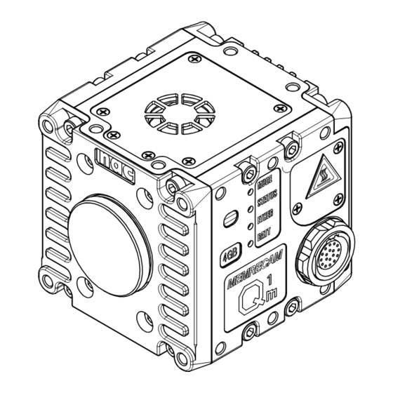
External Appearance and Names for this Unit External Appearance and Names for this Unit ■ External Appearance and Names for this Unit Top, Right Side Air inlet Vents IF connector Color camera identification sticker (not used with black/white cameras) Memory size sticker (00375) - Page 24 External Appearance and Names for this Unit Left side, Bottom Air inlet Vents (00375)
- Page 25 External Appearance and Names for this Unit Front, Back Lens mount Steel plate (indicating the production number) (00375)
- Page 26 External Appearance and Names for this Unit ■AC POWER SYSTEM External Appearance and Names DC connector Power switch AC cable (00375)
-
Page 27: Flow Of Operations
Flow of Operations Flow of Operations Q1m/Q1v is operated with the Windows control software HXLink. The flow for basic recording, playback and storage on this device is shown in the following figure. Read the “HXLink User’s Manual” for the HXLink control software. (00375) - Page 28 1-10 (00375)
- Page 29 Preparations Set Up this Unit ..........2-2 Mount the Lens ..........2-4 Connect the Equipment and Cables ....2-5 Status LED ............2-10 Turn the Power ON/OFF ........2-11 (00375)
-
Page 30: Set Up This Unit
Set Up this Unit Set Up this Unit This describes the method of setting up for filming with the MEMRECAM Q1m/Q1v. ■Mounting the Camera There are air inlets and exhaust vents on this device for cooling, and ventilation occurs with a fan. -
Page 31: Mounting On A Tripod
Set Up this Unit ■ Mounting on a Tripod Mount the included tripod plate to the camera when mounting the camera on the tripod. The mounting screws can be used to mount tripods with diameters of 1/4-20UNC (small screw) and lengths of 8mm or less. -
Page 32: Mount The Lens
Mount the Lens Mount the Lens This describes how to mount and remove the C mount lens. ■Mount the Lens 1 Remove the mount cap Remove the Q1m/Q1v mount cap and lens cover. 2 Mount the lens Line up the screw part of the lens and mount (①) and turn until the lens stops (②) . -
Page 33: Connect The Equipment And Cables
Connect the Equipment and Cables Connect the Equipment and Cables This describes the connections for peripherals for filming such as the power as well as the cables. ■ Input/Output Connectors Table of Input/Output Connectors Connector Branched Connector Input/Output Signal DC IN Power input ETHER 10/100/1000BASE-T Ethernet... - Page 34 Connect the Equipment and Cables Connection Drawing The Q-CAM cable, AC POWER SYSTEM and Windows PC controller are sold separately. (00375)
- Page 35 Connect the Equipment and Cables ■ Connect the Q-CAM Cable Connect the Q-CAM cable sold separately. 1 Connect the Q-CAM cable to the camera Line up the red arrow of the Q-CAM cable plug with the IF connector on the camera and plug in until it clicks. 2...
- Page 36 Connect the Equipment and Cables ■ Connect the Power Connect the MINI AC POWER SYSTEM sold separately. 1 Turn the power switch OFF Turn the AC adapter power switch OFF. 2 Connect the AC cable to the AC adapter 3...
- Page 37 Connect the Equipment and Cables ■ Connect a Windows PC Controller Connect to a PC using an Ethernet cable. 1 Connect an Ethernet cable to the Ethernet connector of the Q-CAM cable. Connect a Windows PC Connect the Ethernet cable to the Ethernet (RJ45) connector of the Q-CAM cable.
-
Page 38: Status Led
Status LED Status LED Confirmation of the MEMRECAMC Q1m/Q1v status can be made with the status LED. Status LED The four status LED on the right side of the unit display the camera status. Status LED Operation Orange REC mode (Flashing:set to EST mode, EST pulse input) (Flashing) Blue STOP/READY mode... -
Page 39: Turn The Power On/Off
Turn the Power ON/OFF Turn the Power ON/OFF Turn the power on to start up the MEMRECAM Q1m/Q1v. ■ Start up the Q1m/Q1v 1 Turn ON the power switch of the AC adapter Turn the switch ON after verifying the cable is connected to the AC adapter and camera. - Page 40 Turn the Power ON/OFF ■ Turn Off the Q1m/Q1v Power 1 Disconnect the HX Link and camera with the Windows PC Make sure to save the recorded image before disconnecting. Disconnect the HX Link and Q1m/Q1v. Turn OFF the AC adapter power switch If the AC adapter power is turned off when the memory backup battery is not charged, the recorded images are removed from the memory of this unit.
-
Page 41: Basic Operations
Basic Operations Register the Image Correction Data ....3-2 Trigger Input (REC Mode) ....... 3-21 Using HXLink ............. 3-4 Memory Backup ..........3-22 Get the Black Balance ........3-6 Playback (PLAY Mode) ........3-24 Stop (STOP Mode) ..........3-9 Changing the Frame Rate ......... 3-26 Display Live Images (VIEW Mode) .... -
Page 42: Register The Image Correction Data
Register the Image Correction Data Register the Image Correction Data There is fixed pattern noise (FPN) on the sensor used with the Q1m/Q1v. Register the image correction data in the control Windows PC application for this correction processing. The image correction data is exclusive to this camera. Register each camera to the Windows PC controller. - Page 43 FPN Data Settings Do not change the name or extension of the files copied. Register the image correction data with the same procedure, even if using Q1m/Q1v that are not set. The image correction data CD may be updated. In that case, overwrite the newest image correction data.
-
Page 44: Using Hxlink
Using HXLink Using HXLink A special application is required to operate the Q1m/Q1v. This describes the basic operations to use HXLink. Refer to the included HXLink guide for the installation method or detailed method of use for the applications. HXLink GUI The HXLink GUI includes a “Basic Mode”... - Page 45 Using HXLink Connect the Camera Press the camera connection. Press the camera connection button on Add Item. 2 Select the connected camera from the list. Once the camera that can be connected is displayed on the list, select the camera to be used and press “OK”.
-
Page 46: Get The Black Balance
Get the Black Balance Get the Black Balance Get the black balance (noise and black level correction data) to correct the fixed pattern noise of the sensor. Noise can be generated on the image sensor used with the Q1m/Q1v depending on the temperature of the sensor or the recording settings. - Page 47 Get the Black Balance The black balance is saved in the PC connected. Make sure to get the black balance if the camera is connected to another PC. Get the Black Balance Set the “frame rate” and “frame size” for filming.
- Page 48 Get the Black Balance 4 Press the update black balance button The following statuses are recommended. NONE:The black balance isn’t ready. BUSY:Getting the black balance. VALID:Finished getting the black balance. 5 Enable/disable the black balance Select ON/OFF to enable/disable the setting. ON:Use black balance corrected data.
-
Page 49: Stop (Stop Mode)
Stop (STOP Mode) Stop (STOP Mode) After startup, the MEMRECAM Q1m/Q1v enters the STOP mode. ■ Switch to the STOP mode Press the stop button during each mode The STOP mode can be access from other camera modes, including the VIEW mode and the ARM mode. -
Page 50: Display Live Images (View Mode)
Display Live Images (VIEW Mode) Display Live Images (VIEW Mode) Display live images in the VIEW mode for the recording settings or to adjust the camera and lens. ■ Switch to the VIEW Mode Press the view/record button during each mode ... -
Page 51: Basic Recording Settings
Basic Recording Settings Basic Recording Settings Select the frame rate, frame size and shutter speed according to the image photographed. ■ Select the Frame Rate Sets the frame rate (frames per second) according to the image and subject filmed. 1 Access the VIEW mode ... - Page 52 Basic Recording Settings ■Select the Frame Size Sets the frame size according to the image and subject filmed. 1 Access the VIEW mode Switch to the VIEW mode (A 3-10). 2 Select the frame size The frame rate is limited by the frame size. The frame rate changes as the frame size increases.
- Page 53 Basic Recording Settings Frame Rate and Frame Size Q1m Frame Size Frame Rate (pps) ○ ○ ○ ○ ○ ○ ○ ○ ○ ○ ○ ○ ○ ○ ○ ○ ○ ○ ○ ○ ○ ○ ○ ○ ○ ○ ○...
- Page 54 Basic Recording Settings Frame Rate and Frame Size Frame Size Frame Rate (pps) ○ ○ ○ ○ ○ ○ ○ ○ ○ ○ ○ ○ ○ ○ ○ ○ ○ ○ ○ ○ 1,000 ○ ○ ○ ○ ○ ○ ○...
- Page 55 Basic Recording Settings ■Select the Shutter Speed Sets the shutter speed according to the image and subject filmed. 1 Access the VIEW mode Switch to the VIEW mode (A 3-10). 2 Select the shutter speed The upper limit for the shutter speed is determined by the frame rate. If using black balance, redo the black balance again after changing the frame rate.
- Page 56 Basic Recording Settings Shutter Speeds that can be Selected Preset Shutter Speeds OPEN、 1/100、 1/250、 1/500、 1/1,000、 1/2,000、 1/5,000、 1/10,000、 1/20,000、1/50,000 Preset Shutter Speeds OPEN、 1/100、 1/250、 1/500、 1/1,000、 1/2,000、 1/5,000、 1/10,000、 1/20,000、1/50,000 For speeds other than the preset shutter speeds, set using the custom shutter. ■Set a Custom Shutter Speed 1...
-
Page 57: Using The Low Light Function
Using the Low Light Function Using the Low Light Function There are times when a clear and crisp live image cannot be obtained in the VIEW mode with the set frame rate. Use the low light function to display an image that is brighter than the image filmed with the set frame rate, and easily check the angle of view and the focus. - Page 58 Using the Low Light Function 3 Select the brightness (exposure time) when the low light function is enabled. 100: Displays the live image at an exposure time of 1/100 sec (corresponds to a frame rate of 100 frames/sec, OPEN shutter) ...
-
Page 59: Start Recording (Arm Mode)
Start Recording (ARM Mode) Start Recording (ARM Mode) After making the recording settings, switch to the ARM mode and start recording. Make sure to save the recorded image to the memory before switching to the ARM mode. Once switched to the ARM mode, the image saved in the memory is overwritten and deleted. ... - Page 60 Start Recording (ARM Mode) Ring Buffer In the ARM mode, the Q1m/Q1v continues recording images to the memory. The memory has a cyclic structure (ring buffer), and once that section of the memory is full, the old images are erased in the order from the first image recorded and the new images are overwritten.
-
Page 61: Trigger Input (Rec Mode)
Trigger Input (REC Mode) Trigger Input (REC Mode) Input the trigger that matches the images to be photographed and then end recording. ■ Trigger Input Press the TRIG button while in the ARM mode Switch to the REC mode. ... -
Page 62: Memory Backup
Memory Backup Memory Backup When the memory backup function is enabled, it is possible to save recorded images in the memory even if the power to the main unit is turned OFF by using the power from the AC adapter or internal battery. - Page 63 Memory Backup Red:Memory backup enabled (AC power+battery) Battery charge:Low The memory backup time is shortened due to the low battery charge. Use the memory backup function after charging. Flashing Red:Memory backup enabled (battery only) Battery charge:Low Plug in the AC adapter and charge the battery as soon as possible. Charging will start once power is supplied from the AC adapter.
-
Page 64: Playback (Play Mode)
Playback (PLAY Mode) Playback (PLAY Mode) Plays back the recorded image. ■ Playback Press PLAY while in the STOP mode Switch to the PLAY mode from the STOP mode to play the recorded images. The item list STATUS will be PLAY. 3-24 (00375) -
Page 65: Operating Buttons
Playback (PLAY Mode) Operating Buttons Jump to the Start Frame Displays the playback start frame. Rewind 1 Frame Rewinds 1 frame when in the STOP mode. Stop Stops the PLAY, VIEW and ARM modes and enters the STOP mode. Play/Loop Switches to the PLAY mode from the STOP mode. -
Page 66: Changing The Playback Speed
Changing the Playback Speed Changing the Playback Speed The playback speed can be changed. Reverse playback can also be set. ■ Changing the Playback Speed Select the playback speed with the playback speed pull-down menu. ・ The playback speed will be displayed and can be set. Table of Playback Speeds that Can Be Set Playback Playback Speed (Unit:Frames/Second) -
Page 67: Saving Images
Saving Images Saving Images Download recorded images. Do not set the black balance before saving the memory backup data. ■Save 1 Access the STOP mode Switch to the STOP mode. (A3-9) 2 Click on download 3-27 (00375) - Page 68 Saving Images “Save As” is displayed Click save to execute the save settings File Name: File name for saving File Type:Type of file for saving Start Save: Start frame for range to be saved End Save: End frame for range to be saved ...
- Page 69 Saving Images 5 The file name is displayed once saving has been completed Playback is possible once the saved file is displayed. The saved file is added to the item list. 3-29 (00375)
-
Page 70: Load And Save Settings
Load and Save Settings Load and Save Settings If the Q1m/Q1v and HXLink are disconnected, the settings are initialized at the next connection. Save the settings if the settings must be retained, and after connecting the next time, load the settings. - Page 71 Load and Save Settings ■ Load the Settings 1 Select the camera settings to be loaded Select the camera settings to be loaded from the file menu. 2 Load the settings file Select the saved settings file to open. 3-31 (00375)
-
Page 72: Disconnect The Hxlink And Camera
Disconnect the HXLink and Camera Disconnect the HXLink and Camera Disconnect the Q1m/Q1v and HXLink. The camera settings will be initialized if disconnected. Save the settings before disconnecting (A 3-30). ■ Disconnect 1 Select the camera to be disconnected from the item list ... - Page 73 Disconnect the HXLink and Camera If “Close All” is pressed, all of the cameras and files on the item list will be disconnected and closed. 3-33 (00375)
- Page 74 3-34 (00375)
-
Page 75: Specifications
Specifications Image Sensor ............ 4-2 Recorder............4-7 System Control ..........4-14 Input/Output Connectors ......4-17 Shape, Environment, Application Standards, Precision, Supplies ......... 4-20 Main Attachments, Options ......4-21 Dimensional Drawings ........4-23 (00375) -
Page 76: Image Sensor
1280 × 1024 pixels (1,310,000 pixels) Maximum Area 7.17 × 5.73 mm Precision Around the Optical ±0.33 mm Axis ■ Image Sensor MEMRECAM Q1v Format Approximately 1/1.8 inch CMOS sensor (color/B/W) Valid Pixels 640 × 480 pixels (300,000 pixels) Maximum Area 7.17 × 5.38 mm Precision Around the Optical ±0.33 mm... - Page 77 Image Sensor ■Frame Rates MEMRECAM Q1m Preset Frame Rates 50, 60, 100, 250, 500, 1,000, 2,000, 2,500, 2,800, 3,000, 4,000, 5,000, 6,000, 8,000, 9,000, 10,000, 20,000, 30,000, 40,000, 50,000, 87,000 frames/sec ■ Frame Rates and Valid Pixels MEMRECAM Q1m Preset Maximum Frame Rate and Valid Pixels (Area) Maximum Frame Valid Pixels...
- Page 78 50, 60, 100, 250, 500, 1,000, 1,500, 2,000, 2,500, 3,000, 4,000, 4,500, 5,000, 6,000, 8,000, 9,000, 10,000, 15,000, 20,000, 30,000, 40,000, 50,000, 70,000, 87,000 frames/sec ■ Frame Rates and Valid Pixels MEMRECAM Q1v Preset Maximum Frame Rate and Valid Pixels (Area) Maximum Frame...
- Page 79 ※ The brightness of the subject is the brightness when the output signals reach 100% for the subject at a reflectance of 89% and the f-stop value is the aperture stop for the lens at that time. ■Sensitivity MEMRECAM Q1v Color ISO8,000 (720lx, F4, 1000frames/sec, shutter 1/1000s, Digital Gain:NORMAL)
-
Page 80: Lens Mount
Image Sensor ■ Lens Mount Type of Mount C Mount (there may be vignetting depending on the image resolution) ■ Timing Compatibility with Existing Products Q1m/Q1v Standard Timing Shutter exposure start timing (GX native) fx Compatible Timing Shutter exposure end timing (K4 compat) (00375) -
Page 81: Recorder
Recorder Recorder ■ Recording Memory Capacity Internal Memory Capacity 4GB / 8GB ■Recording Bit Length Image Sensor Output 12 bit Recording bit per pixel Select from 8/10/12 bits 12 bit: Records with 12 bit image sensor output (high quality image) 10 bit:... - Page 82 Recorder ■ Recording Time MEMRECAM Q1m 4GB Model Preset settings Valid Pixels Recording Time (Sec) Frame Rate 12 bit 10 bit (frames/sec ) Horizontal Vertical ※16 bit ※16 bit 8 bit recording recording 1280 1024 2,000 0.81 0.81 1.62 1024 2,500 1.08 1.08...
- Page 83 Recorder 8GB Model Preset settings Valid Pixels Recording Time (Sec) Frame Rate 12 bit 10 bit (frames/sec ) Horizontal Vertical ※16 bit ※16 bit 8 bit recording recording 1280 1024 2,000 1.62 1.62 3.26 1024 2,500 2.17 2.17 4.34 1280 2,800 1.65 1.65...
-
Page 84: Recording Time
Recorder ■Recording Time MEMRECAM Q1v 4GB Model Preset settings Valid Pixels Recording Time (Sec) Frame Rate 12 bit 10 bit (frames/sec ) Horizontal Vertical ※16 bit ※16 bit 8 bit recording recording 8,000 0.86 0.86 1.73 9,000 10,000 1.92 1.92 3.84... - Page 85 Recorder 8GB Model Preset settings Valid Pixels Recording Time (Sec) Frame Rate 12 bit 10 bit (frames/sec ) Horizontal Vertical ※16 bit ※16 bit 8 bit recording recording 8,000 1.73 1.73 3.47 9,000 2.41 2.41 4.83 10,000 3.86 3.86 7.72 15,000 5.79 5.79...
-
Page 86: Trigger Timing
Recorder ■ Live Image Output Output Method PC live output with Ethernet GigE Vison Raw data of images the PC receives from MEMRECAM is converted to images for display Refresh Rate Depends on the network status between the MEMRECAM and the PC as well as the recording resolution ・About 5 frames/sec When the display resolution is1280x1024... - Page 87 Recorder ■ Simultaneous Recording Data Recorded Scene Number Closed caption method Recording Trigger Mode Setting Closed caption method Frame Rate Closed caption method Frame Size Closed caption method Shutter Speed Closed caption method Recording Image Quality Settings Closed caption method Recording Comments Closed caption method Trigger Time...
-
Page 88: System Control
System Control System Control ■ Status LED CAMERA Orange: REC mode (during camera image memory recording Camera Mode Display after camera image output and trigger detection) Blue: STOP/READY mode (memory image output. Playback or transmission mode immediately after startup) White: VIEW mode (keeps the camera image output and contents recorded in the memory) Magenta:... - Page 89 System Control MEM BACKUP Lit green: Backing up with external power, battery (full charge) Flashing green: Backing up with battery (full charge) Lit orange: Backing up with external power, battery (medium charge) Flashing orange: Backing up with battery (medium charge) Lit red:...
- Page 90 System Control ■ Memory Backup Function Protects images just recorded when the power switch is turned OFF accidentally after recording is finished or protects the contents of the recorded images when the power cable is disconnected and the power is cut off during recording.
-
Page 91: Input/Output Connectors
Input/Output Connectors Input/Output Connectors ■IF Connector Application Camera power input, Ethernet connection, EST input, trigger input, EPO output, power control Model LEMO ECA.2B.318 Plug LEMO FGA 2B.318 ETHER 1000BASE-T (IEEE802.3ab), 100BASE-TX (IEEE802.3u), insulator SYNC IN Signal Level: CMOS level, 5V pull-up, insulator L level:-0.5VDC (minimum applied voltage) ~... - Page 92 Input/Output Connectors SYNC OUT Signal level: 5VCMOS output, insulator Function: Falling (H→L) :Start exposure Rising (L→H) :End exposure Polarity inverting function PWRCTL Signal level: CMOS level, 5V pull-up, insulator L level:-0.5VDC (minimum applied voltage) ~ 1.2VDC H level : 3.6VDC ~ 5.5VDC (maximum applied voltage) Function:...
- Page 93 Input/Output Connectors Pin Arrangement Direction Function ・Input/Output Level Notes Name MDI 0+ 10/100/1000BASE-T Interface MDI 0- 10/100/1000BASE-T Interface MDI 1+ 10/100/1000BASE-T Interface 10/100/1000BASE-T Interface MDI 2+ 10/100/1000BASE-T Interface 10/100/1000BASE-T Interface MDI 3+ 10/100/1000BASE-T Interface 10/100/1000BASE-T Interface SYNC IN CMOS, contact Insulator SYNC IN RTN CMOS, contact...
-
Page 94: Shape, Environment, Precision, Application Standards, Supplies
Shape, Environment, Precision, Application Standards, Supplies Shape, Environment, Precision, Application Standards, Supplies ■ Shape Exterior dimensions (W×H×D) About W62×H62×D65mm (Excluding connector, protruding parts and mounting parts) Main unit weight About 470g (Camera unit only. Excluding mounting cap and such) Mounting screws 4 each M4 depth of 5mm on the top, bottom, left and right 4 each M4 depth of 7mm on the front and back ■... -
Page 95: Main Attachments, Options
Main Attachments, Options Main Attachments, Options ■Q-CAM Cable (sold separately) Length 0.5 m Plug Camera side: LEMO FGA.2B.318 Clip to prevent cable from disconnecting (locking clip) Included ETHER: RJ45 receptacle SYNC IN: BNC receptacle TRIG: BNC receptacle SYNC OUT: BNC receptacle POWECNT:... - Page 96 Main Attachments, Options ■AC Adapter (sold separately) External dimensions (W×H×D) Approximately 76 × 43.7 × 184 mm (not including connector) Weight Approximately 1.1 Kg Operating temperature and 0~60℃, 5~95%RH (no condensation) humidity Storage temperature and -40~85℃, 5~95%RH (no condensation) humidity Connector Camera side:...
-
Page 97: Dimensional Drawings
Dimensional Drawings Dimensional Drawings ■MEMRECAM Q1m, Q1v (Same shape for both Q1m, Q1v) 4-23 (00375) - Page 98 Dimensional Drawings ■MEMRECAM Q1m, Q1v Tripod Plate Q1m/Q1v installed (the figure shows the Q1m) 4-24 (00375)
- Page 99 Dimensional Drawings ■Q-CAM Cable L:500±25 (mm) 4-25 (00375)
- Page 100 Dimensional Drawings ■AC Adapter Dimensional Drawing 4-26 (00375)
- Page 101 Dimensional Drawings ■ Anti-G Camera Holder Dimensional Drawing 4-27 (00375)
- Page 102 Dimensional Drawings ■Lens Holder Dimensional Drawing Lenses compatible with the lens holder Produced by KOWA LM3NC1M (f=3.5mm) LM5JC1M (f=5mm) Produced by RICOH FL-CC0814-2M (f=8mm) 4-28 (00375)
Need help?
Do you have a question about the Memrecam Q1v and is the answer not in the manual?
Questions and answers