Table of Contents
Advertisement
Advertisement
Table of Contents

Related Manuals for NAC Image Technology MEMRECAM GX-1 584032-2


Summary of Contents for NAC Image Technology MEMRECAM GX-1 584032-2
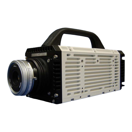
- Page 1 Quick Reference Manual MEMRECAM GX-1 October 5, 2007 NAC Image Technology Inc.
-
Page 2: Table Of Contents
Contents 1. Configuration Overview ・ Standard System ・ Basic Options ・ Other Options 2. I/O Connectors 3. LED Status Indicators 4. Connections ・ Single Camera Operation ・ Multi-Camera Operation 5. Operations ・ Basic Operation Schematics ・ GX Link Operations ・ J-Pad 3 Operations 6. -
Page 3: Configuration Overview
1. Configuration Overview 1.1 Standard System MEMRECAM GX-1, 2GB, Color (584032-2) MEMRECAM GX-1, 2GB, Monochrome (584032-4) ・ 1 x Digital High Speed Camera MEMRECAM GX-1 ・ 1 x Control Software GX Link ・ 1 x J1 I/O Cable (for power input, trigger input, etc.) ・... -
Page 4: Other Options
1.3 Other Options Multi-Camera Network Options ・ GX Hub (584030--) ・ Remote Cable 3m (H12061-3) ・ Remote Cable 7.5m (H12061-5) ・ Remote Cable 15m (H12061-7) ・ Remote Cable 25m (H12061-8) ・ Remote Cable 50m (H12061X0) ・ Remote Cable 75m (H12061X1) ・... -
Page 5: I/O Connectors
2. I/O Connectors MEMRECAM GX-1 has three I/O connectors at the back of the camera. Followings show locations and major usages of each I/O. Please refer to Appendix B for details. J1: Power ・ Power input J3: Remote ・ Trigger input (contact, TTL) J2: VF J-PAD ・... -
Page 6: Led Status Indicators
3. LED Status Indicator MEMRECAM GX-1 indicates its status using five LED’s at the back of the camera. This section will explain features and functions of the LED status indicators. Location and layout LED Status Indicators ・ UB: USB ・ ET: Ethernet ・... - Page 7 3) CM: Camera Mode Status STOP/READY Mode: Blue Status just after boot up or completion of recording, or stop/still in playback. VIEW Mode: White The imager is outputting image signal while the last recording image data is kept in the memory. ARM Mode: Magenta The imager is outputting image signal that is being recorded (overwritten) to the...
-
Page 8: Connections
4. Connections Single Camera Operation M EM RECAM Host PC AC Adapter 1000Base-T Switching Hub CAT5E or CAT6 Cable Max.100m * You can connect the GX1 to a Laptop PC directly using a CAT5E/CAT6 cable. Local Single Camera Operation (w/o PC) J-Pad 3 Viewf inder M EM RECAM... -
Page 9: Multi-Camera Operation
Multi-Camera Operation Up to 100m M EM RECAM GX-Hub Remote Cable M EM RECAM up to 100m GX-Hub Host PC Up to 100m M EM RECAM GX-Hub 1000Base-T Switching Hub CAT5E or CAT6 Cable Max.100m M EM RECAM GX Remote Cable(Copper) Max.100m... -
Page 10: Operations
5. Operations 5.1 Basic Operation Procedures Power On Boot Up Ready Playback View Download Power Off Auto View Mode Triggered Memory Backup Recording Done... -
Page 11: Gx Link Operations
5.2 GX Link (Control S/W) Operations Network Settings at PC * IP address settings * TCP/IP optimization Connection Boot up GX Link Click a camera button GX Link identifies all applicable cameras Attach a camera (s) Ready Playback View Download Camera Auto View Mode Operation... -
Page 12: J-Pad 3 Operations
5.3 J-Pad 3 Operations 1) General J-Pad 3 is an optional remote controller useable for the Memrecam GX series. It allows you to operate most of the functions of the camera without a control PC (GX Link). Important: Settings in GX Link (control software) are prior to settings in the camera. Therefore, even if you set the parameters of the camera using the J-Pad, all settings will be followed to the GX Link settings once you connect the control PC to the camera. - Page 13 Lock Switch ・ Settings can be locked by a slide switch at side of the J-Pad to prevent mis-operation. 5) LCD Spec: 128 x 64 dots, monochrome, backlight Contents of display ・ Status: Mode, Frame Rate, Frame Size, Shutter, Trigger Mode, ID, Scene, Frame Counter, Time, Payback Range tool bar ・...
- Page 14 6) Appearance...
- Page 15 7) Functions of Keys a) Setup Keys MENU MENU Enters Menu for: ・General Setup <TOP MENU> ・Recording Setup <VIEW MENU> ・System Setup <SYSTEM SETUP MENU> Ends Menu Sets the parameter Moves a cursor to upward DOWN Moves a cursor to downward LEFT Moves a cursor to left RIGHT...
- Page 16 c) Direct Setting Keys Following keys allow you to set essential parameters and functions directly as regards recording, playback and data download. FRM RATE FRM RATE Set Key: sets frame rate. SHUTTER SHUTTER Set Key: sets shutter speed. TRIG TRIG Set Key: sets trigger position. S.SET Set Key: sets a start frame in playback/download.
- Page 17 d) Combination Key Operations + Jumps to the start frame in STOP status. Jumps to the end frame in STOP status. + Enters a maintenance menu setting for; + NTSC/PAL ・ IP address ・ ・ Reset to default settings e) Jog Dial PUSH CW for upward, CCW for downward, Push for set.
-
Page 18: Specifications
6. Specifications • Sensor: 12-bit, 1.3M-pixel CMOS sensor • Frame Rate: 50-200,000pps • Resolution: 1,280 x 1,024pixels up to 2,000pps 640 x 480pixels up to 6,000pps 512 x 384pixels at 10,000pps * See Appendix A for more details • Electronic Shutter: OPEN to 3µ sec. * See Appendix A for more details •... - Page 19 -Appendix A- Frame Rate, Resolution, Sensing Area & Exposure Time Frame Resolution in Sensing Max. Min. Setting Rate largest or square Area Exposure Exposure Step (pps) format (pixels) (mm) (µ sec) (µ sec) (µ sec) 1,280 x 1,024 27.78 x 22.22 9,996 1 or 2 1,280 x 1,024...
- Page 20 -Appendix B- DC 24V IN DC Return EST IN EST GND Trigger Signal IN (make contact/TTL) Trigger Signal GND ARM Status OUT ARM Status GND FAULT Status OUT FAULT Status GND ARM Command IN GND (ARM Command Return) USB VBUS USB D+ USB D- USB GND...
- Page 21 Ethernet Signal MDI 0+ Ethernet Signal MDI 0- Ethernet Signal MDI 1+ Ethernet Signal MDI 1+ Ethernet Signal MDI 2+ Ethernet Signal MDI 2- Ethernet Signal MDI 3+ Ethernet Signal MDI 3- EST IN EST GND IRIG Signal IN IRIG Signal GND Trigger Signal IN A (Photo coupler anode, +current) Trigger Signal IN C (Photo coupler cathode, -current) Exposure Pulse Signal OUT...
-
Page 22: Dimensional Drawings
-Appendix C- Dimensional Drawing... - Page 23 Mounting Plate 8 0 8 0 6 ×φ6 . 4 2 ×3 /8 -1 6 U N C φ4 . 3 3 6 3 8 5 0 1 7 2...
Need help?
Do you have a question about the MEMRECAM GX-1 584032-2 and is the answer not in the manual?
Questions and answers