Table of Contents
Advertisement
Quick Links
REVISED SEP. 2002
MARINE VHF RADIOTELEPHONE
Instruction Manual
JHS-32B
JHS-32B
MARINE VHF RADIOTELEPHONE
CH16
25/1W
P
1
2
4
5
7
8
.
0
SP
DIM
POWER
PRESS BOTH OFF
HANDSET
DSC ALM
DISTRESS & URGENCY
OTHERS
OPE
CH70
DISTRESS
DW
ALM/CALL
ALM
3
STOP
DISABLE
6
COUNTRY
WX
M
9
CLR
SCAN
MENU
PRINT
OFF
CALL
ENTER
SQL
VOL
Advertisement
Table of Contents

Subscribe to Our Youtube Channel
Related Manuals for JRC JHS-32B


Summary of Contents for JRC JHS-32B
- Page 1 REVISED SEP. 2002 MARINE VHF RADIOTELEPHONE JHS-32B Instruction Manual JHS-32B MARINE VHF RADIOTELEPHONE DSC ALM DISTRESS & URGENCY OTHERS CH16 CH70 DISTRESS 25/1W ALM/CALL STOP DISABLE COUNTRY SCAN MENU PRINT POWER CALL ENTER PRESS BOTH OFF HANDSET...
- Page 3 〈 〈 〈 〈 Before Operation 〉 〉 〉 〉 WARNING In accordance with IMO MSC Circular 862, the apparatus equipped on or after 1 February 1999, the procedure of distress-call activation is modified to prevent false call. In emergency, press and hold “DISTRESS” button until beeping sound changes from intermittent to continuous.
- Page 4 1.Usual display : MODE: SIMP TEL OUTPUT: 25W OPE : MASTER ALARM : ENABLE When connecting with GPS, date, UTC , latitude, SCAN: OFF : CLOSE and longitude data from GPS is displayed. SP : ON POWER : AC 01 JAN 2000 23:59 UTC S: 12゜34゛...
- Page 5 5.Select a combination of latitude / longitude key. ▼ ▲ - - INPUT POSITION/UTC DATA - - POSITION : N ・The selected combination of latitude / longitude is highlighted. DATE SELECT WITH ▼ ▲ ,& PRESS ENTER. PRESS CLR TO CANCEL. Press key.
- Page 6 Input the UTC time when latitude / longitude is 8. measured. - - INPUT POSITION/UTC DATA - - POSITION : S12.34 W123.45 ・ Example of an input of 12:34 UTC : : 12:34 (HH:MM) Press keys. DATE : 31.12.99 (DD.MM.YY) Input UTC time, not local time.
- Page 7 Press key. 13. STOP ・The screen returns to usual display and the manually entered position / UTC / date information are displayed. MODE: SIMP TEL OUTPUT: 25W ・When no position / UTC data is received OPE : MASTER ALARM : ENABLE SCAN: OFF : CLOSE from GPS, or when no position / UTC...
-
Page 9: Cautions Against High Voltage
CAUTIONS AGAINST HIGH VOLTAGE Radio and radar devices are operated by high voltages of anywhere from a few hundred volts up to many hundreds of thousands of volts. Although there is no danger with normal use, it is very dangerous if contact is made with the internal parts of these devices. -
Page 10: First Aid
First aid ☆Note points for first aid Unless there is impending danger leave the victim where he or she is, then begin artificial respiration. Once you begin artificial respiration, you must continue without losing rhythm. (1) Make contact with the victim cautiously, there is a risk that you may get electrocuted. (2) Switch off the machinery and then move the victim away slowly if you must. - Page 11 ☆If the victim has a pulse but is not breathing ("Mouth to mouth" resuscitation) Figure 1. (1) Place the victim's head facing backward (place something under the neck like a pillow). (2) Point the chin upward to widen the trachea. (3) Pinch the victim's nose, take a deep breath, then put your mouth over the victim's mouth and exhale completely, making sure that your mouth completely covers the victim's mouth.
- Page 12 ☆If the victim has no pulse and is not breathing (Heart massage in combination with artificial respiration.) Figure 2 If the victim has no pulse, his or her pupils are dilated, and if you cannot detect a heartbeat, the heart may have stopped, beginning artificial respiration is critical.
-
Page 13: Preface
Preface Thank you for choosing the JHS-32B International VHF Radiotelephone. This unit can be used as a VHF radiotelephone in the Global Maritime Distress and Safety System (GMDSS) and is installed on small and large ships to make distress calls and normal calls. This unit complies with international regulations. -
Page 14: Before Operation
Before Operation Concerning the symbols This manual uses the following symbols to explain correct operation and to prevent injury or damage to property. The symbols and descriptions are as follows. Understand them before proceeding with this manual. Indicates a warning that, if ignored, may result in WARNING serious injury or even death. -
Page 15: Handling Precautions
This unit is also used for distress communication, in addition to usual communication. Contact JRC or our agent if any problem is observed in this unit on usual operation or inspection. Do not ignore and leave any problems of this... -
Page 16: Caution
Handling Precaution CAUTION Do not use this equipment for anything other than specified. Doing so may cause failure or malfunction. Do not turn the trimmer resistors or the trimmer capacitors on the PCB unit, except when and if they need to be adjusted. Doing so may cause failure or malfunction. - Page 17 CAUTION To operate this unit, an ID number must be assigned before operation. If one has not yet been assigned, contact our agent or service center. To check if it is registered or not, see "4.3.19 Reviewing System Setup" in this manual.
-
Page 18: Distress Calls
DISTRESS CALL DISTRESS CALL Making a Distress Call CAUTION Do not make a distress call except in an emergency. When making a distress call, follow the instructions of the ship’s captain or officer in charge. OPERATION Open the DISTRESS switch cover. DSC ALM DISTRESS &... -
Page 19: Terminating Transmission Of A Distress Call
• A distress call has priority over all other operations. • The distress message is first transmitted 5 times consecutively, followed by random intervals of 3.5 to 4.5 minutes thereafter. This process is repeated until a response is received. • When a navigation system is connected, position and time data from the system is automatically added to the distress massage. -
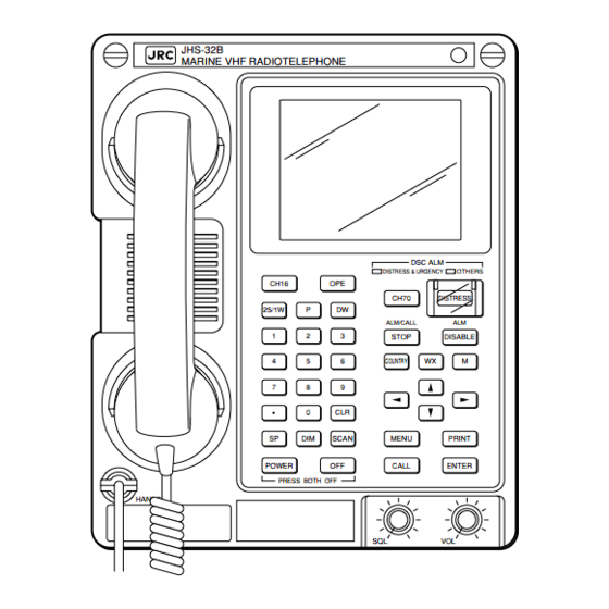
Page 20: External Views
EXTERNAL VIEWS JHS-32B VHF Radiotelephone JHS-32B MARINE VHF RADIOTELEPHONE DSC ALM DISTRESS & URGENCY OTHERS CH16 CH70 DISTRESS 25/1W ALM/CALL STOP DISABLE COUNTRY SCAN MENU PRINT POWER CALL ENTER PRESS BOTH OFF HANDSET NCH-414 Remote Controller NCH-414 MARINE VHF RADIOTELEPHONE CONTROLLER DSC ALM DISTRESS &... - Page 21 NKG-52 Printer MRE-332 Guard Receiver NRE-332 NKG-52 VHF GUARD RECEIVER PRINTER BUSY BUSY FEED RESET CHANNEL CHANNEL ALM OFF VOLUME VOLUME POWER POWER NQE-846 Handset Connection Box NQE-847 Handset Connection Box (Waterproof Wing Mount Type) (Indoor Flush Mount Type) HANDSET HANDSET...
-
Page 22: Table Of Contents
(8)NVS-423A External Speaker ............... 28 (9)11209+505 Antenna with Fitting ..............29 (10)HS-6000JRC11/J5 Handset ............... 29 (11)UBP-51-10 Handset Hook ................. 29 1.5 Block Diagram ....................... 30 1.6 Main Unit Block Diagram ....................31 1.7 Parts Layout Diagram of Main Unit (JHS-32B) ............32... - Page 23 2 NAMES AND FUNCTIONS ..........35 2.1 Main Unit ........................36 2.2 Main Displays ........................ 38 3 INSTALLATION .............. 44 4 OPERATION ..............45 4.1 Basic Communication (Telephone Mode) ..............45 4.1.1 Turning the Power ON/OFF ................46 4.1.2 Receiving Calls ....................47 4.1.3 Transmitting ......................
- Page 24 5.2.2 Guide to Locating Faults ................... 122 6 AFTER-SALES SERVICE ..........123 7 DISPOSAL ..............124 8 SPECIFICATIONS ............125 8.1 Main Unit (JHS-32B) ....................125 8.2 Channel Assignment Tables ..................127 (1) ITU Channels ....................... 127 (2) USA Channels ...................... 128 (3) CANADA Channels ....................
-
Page 25: Definition Of Terms
DEFINITION OF TERMS General Terms This chapter contains definitions of terms related to general operation, and also describes the general maritime terms and radio terms. DSC : RCC : Digital Selective Calling System Rescue Co-ordinate Center. GMDSS : R.R : Global Maritime Distress and Safety System Radio Regulations GPS :... -
Page 27: Equipment Overview
Functions The JHS-32B includes the VHF radiotelephone and DSC watchkeeping receiver required by the Global Maritime Distress and Safety System (GMDSS). It is designed to be compact and lightweight for easy installation in any ship of 100 gross tons or more, as well as in conven- tional ships (all passenger and cargo ships of over 300 gross tons engaged in international navigation). -
Page 28: Features
A message stored in tion of specific countries. memory can be manually printed out later on. G The JHS-32B VHF radiotelephone can be set G The brightness of LCD and keypad backlighting is widely adjustable, and will not... -
Page 29: Basic Configuration
NVS-423 Wall mount type External speaker NVS-423A Flush mount type Coaxial cable RG-10/UY For antenna cable Flush mount fittings 4B21367 For JHS-32B Flush mount fittings 4B21368 For NCH-414 Flush mount fittings MPBP02915 For NKG-52 Flush mount fittings 4B21369 For NRE-332... -
Page 30: System Configuration
POWER CALL ENTER PRESS BOTH OFF HANDSET JHS-32B VHF Radiotelephone. The main unit of the VHF radio communi- cation system. In addition to usual voice communication, watchkeeping of digital selective calls is possible using the built- in CH70 DSC receiver. - Page 31 NKG-52 PRINTER FEED NKG-52 Printer RESET Prints out messages. ALM OFF POWER NRE-332 VHF GUARD RECEIVER BUSY BUSY NRE-332 Guard Receiver CHANNEL CHANNEL Enables reception of 2 channels at the same time. VOLUME VOLUME POWER NCH-414 Remote Controller Enables communication at a remote place from the main unit (it is possible to install up to 3 units).
-
Page 32: Dimensions
Dimensions This section shows the external dimensions of each unit. (1)JHS-32B VHF Radiotelephone GWall Mount Type GFlush Mount Type 1.4 Dimensions... -
Page 33: Remote Controller
(2)NCH-414 Remote Controller GWall Mount Type GFlush Mount Type 1.4 Dimensions... -
Page 34: Printer
(3)NKG-52 Printer GWall Mount Type GFlush Mount Type 1.4 Dimensions... -
Page 35: Nre-332 Guard Receiver
(4)NRE-332 Guard Receiver GWall Mount Type GFlush Mount Type 1.4 Dimensions... -
Page 36: Handset Connection Box
(5)NQE-846 Handset Connection Box (6)NQE-847 Handset Connection Box GWaterproof Wing Mount Type GIndoor Flush Mount Type (7)NVS-423 External Speaker GWall Mount Type (8)NVS-423A External Speaker GFlash Mount Type 1.4 Dimensions... -
Page 37: 11209+505 Antenna With Fitting
(9)11209+505 Antenna with Fitting (10)HS-6000JRC11/J5 Handset (11)UBP-51-10 Handset Hook JRC11 :a=275 J5 :a=550 1.4 Dimensions... -
Page 38: Block Diagram
Block Diagram 1.5 Block Diagram... -
Page 39: Main Unit Block Diagram
Main Unit Block Diagram 1.6 Main Unit Block Diagram... -
Page 40: Parts Layout Diagram Of Main Unit (Jhs-32B)
Parts Layout Diagram of Main Unit (JHS-32B) CFF-498B POWER SUPPLY UNIT ANTENNA SWITCH RADIO UNIT UNIT Inside of unit 1.7 Parts Layout Diagram of Main Unit (JHS-32B) - Page 41 DISPLAY UNIT CONTROL UNIT front side KEY BOARD back side Back side of the panel 1.7 Parts Layout Diagram of Main Unit (JHS-32B)
- Page 42 Terminal section 1.7 Parts Layout Diagram of Main Unit (JHS-32B)
-
Page 43: Names And Functions
NAMES AND FUNCTIONS This chapter describes names and functions of the parts of the main unit. Main Unit The parts of the main unit are : JHS-32B MARINE VHF RADIOTELEPHONE DSC ALM DISTRESS & URGENCY OTHERS CH16 CH70 DISTRESS 25/1W... -
Page 44: Main Unit
q LCD Display keys : Move the cursor up or down. w DISTRESS & URGENCY LED : These keys have an automatic repeat Lights up when a distress/urgent call is function which activates after the key has received. been held down for a specific amount of time. - Page 45 #0 [PTT] key : key : Turns the speaker on or off. Enters the transmitting mode. Stops scan- With held down, turns the key click ning. sound on or off. CH16 key : key : Selects CH16. Switches the call mode from Used to enter the decimal point and hy- DSC mode to telephone mode.
-
Page 46: Main Displays
Main Displays This section describes the channel status display, DSC menu display, DSC set up display and window set up display. G Status Display DUAL WATCH CH16 & MODE: SIMP TEL OUTPUT: 25W TX OPE : MASTER ALARM : ENABLE SCAN: OFF : CLOSE : ON... - Page 47 !2 Indicates the current scanning mode. !4 Indicates the mode (communication mode) : Scanning mode is off. ALL CH : Currently scanning all chan- of the currently selected channel. nels. SIMP TEL : Simplex telephone mode MEMORY CH : Currently scanning selected.
- Page 48 G DSC Menu Display --DSC MENU-- CH70 2.ALL SHIPS CALL EDIT 3.INDIVIDUAL CALL EDIT 4.AUTO/SEMI-AUTO TEL CALL EDIT 5.DISTRESS RELAY 6.DISTRESS ACKNOWLEDGEMENT 7.OTHERS ACKNOWLEDGEMENT 8.RECEIVED DISTRESS MESSAGE READOUT 9.RECEIVED OTHERS MESSAGE READOUT 10.TEL NO. REGISTRATION UNACCEPTABLE SELECT WITH , & PRESS ENTER .
- Page 49 G DSC Set Up Display --DISTRESS CALL EDIT-- CH70 FORMAT :DISTRESS NATURE OF DIST :UNDESIGNATED DISTRESS DIST-POSITION :S12.34 W123.45 DIST-UTC :14:59 TELECOMMAND :G3E SIMP TEL END OF SEQUENCE:EOS CALL CH TRANSMITTING SELECT WITH , INPUT NO., & PRESS ENTER . PRESS DISTRESS TO SEND.
- Page 50 G Window Set Up Display --DISTRESS CALL EDIT-- CH70 FORMAT NATURE OF DIST DIST-POSITION DIST-UTC TELECOMMAND END OF SEQUENCE CALL CH UNACCEPTABLE SELECT WITH , & PRESS ENTER . PRESS TO CANCEL. q CH70 is selected. r Instructions for performing the operation. Instructions match the operation.
-
Page 51: Error Messages
G Error Messages Error messages resulting from inappropriate operations are described below. For error messages resulting from malfunctions, refer to “5.1.3 Error Message List”. Error Messages Description UNACCEPTABLE Unacceptable key has been pressed. This message appears for 1 second. PRINTER POWER OFF The printer power is off. -
Page 52: Installation
INSTALLATION CAUTION Leave installation of this equipment to our service center or agents. Special knowledge on selecting the place where the antenna is to be mounted and setting the ID number assigned to the ship is required besides mounting operation. -
Page 53: Operation
OPERATION This chapter describes basic operation (using the unit on CH16), communication on a se- lected channel, and communication using DSC mode. There are two modes, telephone mode and DSC mode. In telephone mode, audio communication is available, using the handset, on CH16 or another selected channel. -
Page 54: Turning The Power On/Off
4.1.1 Turning the Power ON/OFF When the power of the main unit or any remote controller is turned on, all the other controllers are also activated. However, when one of the main unit or remote controllers is turned off, all the other control- lers remain active. -
Page 55: Receiving Calls
4.1.2 Receiving Calls When receiving calls, the voice of the caller can be heard through the speaker. WARNING Whenever a distress call is received, be sure to inform the ship’s captain or officer in charge immediately. There is the possibility of legal repercussions if such a procedure is not followed. -
Page 56: Transmitting
When using the controller which has priority, pick up the handset or press to make a call. Pick up the handset. JHS-32B MARINE VHF RADIOTELEPHONE Press PTT to transmit a request to change to another channel. As long as PTT is being pressed, TX appears at OUTPUT on the display. - Page 57 Release PTT when transmission is complete. The unit returns to reception status. MODE: SIMP TEL OUTPUT: 25W OPE : MASTER ALARM : ENABLE SCAN: OFF : CLOSE : ON POWER : AC 1994 14:59 S: 12°34’ W: 123°45’ Enter a channel number. Example: Enter to select CH20.
- Page 58 Hang up the handset to terminate JHS-32B MARINE VHF RADIOTELEPHONE communication. The CH16 Status Display returns and OFF appears for OPE. When no remote controllers are connected, MASTER remains for OPE. 4.1 Basic Communication (Telephone Mode)
-
Page 59: Communicating Using A Specified Channel
[OPE: OFF], by just pressing the key. When using the controller which has priority, pick up the handset or press to make a call. Pick up the handset. JHS-32B MARINE VHF RADIOTELEPHONE MORE 4.2 Communicating Using a Specified Channel... - Page 60 14:59 S: 12°34’ W: 123°45’ Start the transmission. Press PTT to transmit. Hang up the handset to terminate JHS-32B MARINE VHF RADIOTELEPHONE communication. The CH16 Status Display returns and OFF appears for OPE. When no remote controllers are connected, MASTER remains for OPE.
-
Page 61: Registering A Memory Channel
4.2.2 Registering a Memory Channel Up to 10 channels, from ITU, USA, CANADA, weather, and private channels, can be registered in memory channels for your convenience. OPERATION Press MASTER appears for OPE in the CH16 Status Display. MODE: SIMP TEL OUTPUT: 25W OPE : MASTER ALARM : ENABLE... - Page 62 Select a memory channel using -MEMORY CH REGISTRATION-- CH16 01.CH07 (USA) 07:W2 02.CH60 (CANADA) 08:CH01 03.CH05 The selected channel is highlighted. 04.P01 05.P02 06.W1 SELECT WITH , INPUT CH NO., & PRESS ENTER . PRESS TO ERASE. PRESS STOP TO RETURN. Register a channel --MEMORY CH REGISTRATION-- CH16...
- Page 63 Press STOP --MEMORY CH-- CH16 01.CH07 (USA) 07:W2 The MEMORY CH REGISTRATION Display 02.CH60 (CANADA) 08:CH01 03.CH05 09:CH12 disappears and the MEMORY CH Display 04.P01 appears. 05.P02 11:REGISTRATION 06.W1 INPUT NO., OR SELECT WITH , & PRESS ENTER . PRESS STOP TO RETURN.
-
Page 64: Communicating Using A Memory Channel
[OPE: OFF], by just pressing the key. When using the controller which has priority, pick up the handset or press to make a call. Pick up the handset. JHS-32B MARINE VHF RADIOTELEPHONE Press --MEMORY CH-- CH16 01.CH07 (USA) 07:W2 The MEMORY CH Display appears. - Page 65 14:59 S: 12°34’ W: 123°45’ Start the transmission. Press PTT to transmit. Hang up the handset to terminate JHS-32B MARINE VHF RADIOTELEPHONE communication. The CH16 Status Display returns and OFF appears for OPE. When no remote controllers are connected, MASTER remains for OPE.
-
Page 66: Receiving A Weather Channel
4.2.4 Receiving a Weather Channel Nine weather channels provide weather information along the coastline of North America. CAUTION Weather channels vary from coast to coast. Inquire as to which channel is available locally, or use the scanning feature (refer to “4.2.5 Receiving Using the Scanning Feature”). - Page 67 Press ENTER The Status Display of the selected channel (e.g. CH W3) appears. MODE: SIMP TEL OUTPUT: OPE : MASTER ALARM : ENABLE SCAN: OFF : CLOSE : ON POWER : AC 1994 14:59 S: 12°34’ W: 123°45’ Press CH16 The CH16 Status Display returns.
-
Page 68: Receiving Using The Scanning Feature
4.2.5 Receiving Using the Scanning Feature In scanning mode, the unit searches automatically for receivable signals. The three scanning modes are described below. • ALL CH SCAN : Scans all channels in the selected region. • MEMORY CH SCAN : Scans all channels (up to 10) that are saved as memory channels. •... - Page 69 Specify a scanning range using --SCAN-- CH16 the number keys. 1.ALL CH SCAN 2.MEMORY CH SCAN 3.SELECT CH SCAN ITU CH • A scanning range is only required when using FORM CH01 TO CH88 “3. SELECT CH SCAN”. • Specify the range for ITU, USA, or CANADA channels.
-
Page 70: Communicating In Dsc (Digital Selective Call) Mode
Communicating in DSC (Digital Selective Call) Mode In DSC mode, digital selective calls (distress, urgent, safety, and routine) are available on CH70. Distress calls can be made instantly by pressing or after editing the distress DISTRESS message in the DSC MENU. When the message is edited, data such as time and current position can be added even when no navigation aid is connected. -
Page 71: Transmitting Distress Calls
4.3.2 Transmitting Distress Calls In an emergency, just press to make a distress call. The ID number, position, and UTC time DISTRESS are included in the call. CAUTION Transmit distress calls only in an emergency. Only transmit distress calls under the supervision of the ship’s captain or officer in charge. - Page 72 Press and hold key for DISTRESS --DISTRESS CALL-- CH70 3 to 4 seconds. FORMAT :DISTRESS NATURE OF DIST :UNDESIGNATED DISTRESS DIST-POSITION :S12.34 W123.45 When key is pressed, an intermittent DISTRESS DIST-UTC :14:59 beeping tone sounds. If pressed continuously for TELECOMMAND :G3E SIMP TEL END OF SEQUENCE:EOS 3 to 4 seconds, the beeping tone changes from...
-
Page 73: Stopping Accidental Transmissions
4.3.3 Stopping Accidental Transmissions If a false distress call is transmitted accidentally, stop it immediately. CAUTION By the time is pressed, the distress call has been transmitted. It is STOP therefore vital that local shipping and rescue operations be informed that the transmission was an error. -
Page 74: Receiving Distress Calls
4.3.4 Receiving Distress Calls When a distress call is received, the DISTRESS & URGENCY LED lights up and the alarm tone sounds through the speaker. Up to 20 received distress calls can be stored in memory for future confirmation. When a printer is connected to the unit, any received distress message is automatically output to the printer. -
Page 75: Distress Calls (Manually Adding Position Data)
4.3.5 Distress Calls (Manually Adding Position Data) When no navigation aid is connected, manually add position and time data to the distress message. CAUTION Perform this operation only when there is sufficient time to input the data manually without incurring personal risk. A distress call can be made without position data input. - Page 76 Press ENTER --DISTRESS CALL EDIT-- CH70 FORMAT :DISTRESS N or S and W or E are set, and the display NATURE OF DIST :UNDESIGNATED DISTRESS DIST-POSITION prompts for entering coordinates. DIST-UTC :14:59 TELECOMMAND :G3E SIMP TEL END OF SEQUENCE:EOS CALL CH SELECT WITH , INPUT NO., &...
- Page 77 Press ENTER --DISTRESS CALL EDIT-- CH70 FORMAT :DISTRESS The DIST-UTC setting is confirmed. Then CALL NATURE OF DIST :UNDESIGNATED DISTRESS DIST-POSITION :S12.34 W123.45 CH is highlighted and the default channel (CH70) DIST-UTC :13:25 displayed. TELECOMMAND :G3E SIMP TEL END OF SEQUENCE:EOS CALL CH •...
- Page 78 • An alarm tone sounds, the DISTRESS CALL Display appears, and the distress message is transmit- ted. TRANSMITTING appears on the display. • After the distress message has been transmitted, TRANSMITTING changes to TRANSMITTED. Then NEXT DISTRESS CALL: AFTER 3.6 MIN appears, showing that transmission is completed, and the amount of time (e.g.
-
Page 79: Relaying A Distress Call (Without Editing Data)
4.3.6 Relaying a Distress Call (Without Editing Data) • If a distress call has been logged, but it is not acknowledged by any coast station, it can be relayed adding only the fact that the message is being relayed. • This unit does not relay messages automatically, even when automatic acknowledgement is set to “ON”... - Page 80 Select CALL CH using --DISTRESS RELAY--RECEIVED MESSAGE NO.03 CH70 CATEGORY :DISTRESS CALL CH is highlighted and CH70 (default) is TELECOMMAND1 :DISTRESS RELAY DIST-ID :456789012 displayed initially. NATURE OF DIST :UNDESIGNATED DISTRESS DIST-POSITION :S20.25 W125.30 DIST-UTC :14:20 TELECOMMAND :G3E SIMP TEL •...
-
Page 81: Relaying A Distress Call (Manually Entering Position Data At Relay Station)
(Manually Entering Position 4.3.7 Relaying a Distress Call Data at Relay Station) If a distress call is not acknowledged by any coast station, relay it after entering the position and time data of the ship in distress, as obtained from other sources. OPERATION Press MENU... - Page 82 Select DISTRESS using --ALL SHIPS CALL EDIT-- CH70 FORMAT CATEGORY DISTRESS TELECOMMAND1 URGENCY DIST-ID SAFETY NATURE OF DIST ROUTINE DIST-POSITION SHIP'S BUSINESS DIST-UTC TELECOMMAND END OF SEQUENCE SELECT WITH , & PRESS ENTER . PRESS TO CANCEL. Press ENTER --ALL SHIPS CALL EDIT-- CH70 FORMAT :ALL SHIPS...
- Page 83 Press ENTER --ALL SHIPS CALL EDIT-- CH70 FORMAT :ALL SHIPS The window closes and DIST-ID becomes CATEGORY :DISTRESS TELECOMMAND1 :DISTRESS RELAY highlighted. DIST-ID :000000000 NATURE OF DIST :UNDESIGNATED DISTRESS DIST-POSITION :99.99 999.99 DIST-UTC :88:88 TELECOMMAND :G3E SIMP TEL END OF SEQUENCE:EOS SELECT WITH , INPUT NO., &...
- Page 84 Select a coordinate type using --ALL SHIPS CALL EDIT-- CH70 and press ENTER FORMAT :ALL SHIPS CATEGORY :DISTRESS TELECOMMAND1 :DISTRESS RELAY The display prompts for entering latitude and DIST-ID :896745231 longitude. NATURE OF DIST :UNDESIGNATED DISTRESS DIST-POSITION DIST-UTC :88:88 TELECOMMAND :G3E SIMP TEL END OF SEQUENCE:EOS SELECT WITH...
- Page 85 Select an item using --ALL SHIPS CALL EDIT-- CH70 and press ENTER CATEGORY :DISTRESS TELECOMMAND1 :DISTRESS RELAY DIST-ID :896745231 CALL CH is highlighted and CH70 (default) is NATURE OF DIST :UNDESIGNATED DISTRESS displayed. DIST-POSITION :N12.34 E123.45 DIST-UTC :13:25 TELECOMMAND :G3E SIMP TEL END OF SEQUENCE:EOS CALL CH •...
-
Page 86: Calling All Ships
4.3.8 Calling All Ships When this feature is used, all ships in the coverage area are called. OPERATION Press MENU --DSC MENU-- CH70 1.DISTRESS CALL EDIT The DSC MENU Display appears. 2.ALL SHIPS CALL EDIT 3.INDIVIDUAL CALL EDIT 4.AUTO/SEMI-AUTO TEL CALL EDIT 5.DISTRESS RELAY 6.DISTRESS ACKNOWLEDGEMENT 7.OTHERS ACKNOWLEDGEMENT... - Page 87 Select an item using --ALL SHIPS CALL EDIT-- CH70 and press ENTER FORMAT :ALL SHIPS CATEGORY :ROUTINE TELECOMMAND1 :G3E SIMP TEL The window closes and TELECOMMAND1 is TELECOMMAND2 :NO INFORMATION highlighted. WORK CH :NONE END OF SEQUENCE:EOS CALL CH SELECT WITH , &...
- Page 88 Select a work channel and press --ALL SHIPS CALL EDIT-- CH70 ENTER FORMAT :ALL SHIPS CATEGORY :ROUTINE TELECOMMAND1 :G3E SIMP TEL • Example: To select CH10 TELECOMMAND2 :NO INFORMATION Enter WORK CH END OF SEQUENCE:EOS • CALL CH is highlighted and default (CH70) is CALL CH displayed.
- Page 89 Start the transmission. JHS-32B MARINE VHF RADIOTELEPHONE Press PTT to transmit. Hang up the handset to terminate JHS-32B MARINE VHF RADIOTELEPHONE communication. The CH16 Status Display returns and OFF appears for OPE in the display. When no remote controllers are connected, MASTER remains for OPE.
-
Page 90: Calling A Specific Station
4.3.9 Calling a Specific Station A specific ship or coast station can be called by using its ID number. OPERATION Press MENU --DSC MENU-- CH70 1.DISTRESS CALL EDIT The DSC MENU Display appears. 2.ALL SHIPS CALL EDIT 3.INDIVIDUAL CALL EDIT 4.AUTO/SEMI-AUTO TEL CALL EDIT 5.DISTRESS RELAY 6.DISTRESS ACKNOWLEDGEMENT... - Page 91 Press --INDIVIDUAL CALL EDIT-- CH70 FORMAT • The CATEGORY window opens. ADDRESS ROUTINE CATEGORY DISTRESS • The window contains the following five items: TELECOMMAND1 URGENCY DISTRESS TELECOMMAND2 SAFETY WORK CH SHIP'S BUSINESS URGENCY END OF SEQUENCE SAFETY CALL CH ROUTINE SHIP’S BUSINESS SELECT WITH , &...
- Page 92 Select an item using --INDIVIDUAL CALL EDIT-- CH70 and press ENTER FORMAT :INDIVIDUAL ADDRESS :483192657 CATEGORY :ROUTINE The window closes and WORK CH is highlighted. TELECOMMAND1 :G3E SIMP TEL TELECOMMAND2 :NO INFORMATION WORK CH :NONE END OF SEQUENCE:ACK RQ TELECOMMAND2 is fixed as NO INFORMA- CALL CH TION and cannot be edited.
- Page 93 When the handset is picked up before the work S: 12°34’ W: 123°45’ channel Status Display appears, the display appears immediately. Start the transmission. JHS-32B MARINE VHF RADIOTELEPHONE Press PTT to transmit. Hang up the handset to terminate JHS-32B MARINE VHF RADIOTELEPHONE communication.
-
Page 94: Acknowledging A Call With Request Concerning New Work Channel
Acknowledging a Call With Request 4.3.10 Concerning New Work Channel Use this feature to reply to a call back request specifying another channel and the communication type. OPERATION Press MENU --DSC MENU-- CH70 1.DISTRESS CALL EDIT The DSC MENU Display appears. 2.ALL SHIPS CALL EDIT 3.INDIVIDUAL CALL EDIT 4.AUTO/SEMI-AUTO TEL CALL EDIT... - Page 95 Press --INDIVIDUAL CALL EDIT-- CH70 FORMAT • The CATEGORY window opens. ADDRESS ROUTINE CATEGORY DISTRESS • The window contains the following five items: TELECOMMAND1 URGENCY DISTRESS TELECOMMAND2 SAFETY WORK CH SHIP'S BUSINESS URGENCY END OF SEQUENCE SAFETY CALL CH ROUTINE SHIP’S BUSINESS SELECT WITH , &...
- Page 96 --INDIVIDUAL CALL EDIT-- Select an item using CH70 and press ENTER FORMAT :INDIVIDUAL ADDRESS :368259417 CATEGORY :ROUTINE The window closes and WORK CH is highlighted. TELECOMMAND1 :G3E SIMP TEL TELECOMMAND2 :NO INFORMATION WORK CH :NONE END OF SEQUENCE:ACK RQ TELECOMMAND2 is fixed as NO INFORMA- CALL CH TION and cannot be edited.
- Page 97 When the handset is picked up before the work S: 12°34’ W: 123°45’ channel Status Display appears, the display appears immediately. Start the transmission. JHS-32B MARINE VHF RADIOTELEPHONE Press PTT to transmit. Hang up the handset to terminate JHS-32B MARINE VHF RADIOTELEPHONE communication.
-
Page 98: Requesting Connection To A Public Telephone Subscribers
Requesting a Connection to a Public 4.3.11 Telephone Subscribers A connection to a public telephone subscribers in semi-automatic or automatic mode can be obtained using DSC. OPERATION Press MENU --DSC MENU-- CH70 1.DISTRESS CALL EDIT The DSC MENU Display appears. 2.ALL SHIPS CALL EDIT 3.INDIVIDUAL CALL EDIT 4.AUTO/SEMI-AUTO TEL CALL EDIT... - Page 99 Press -AUTO/SEMI-AUTO TEL CALL EDIT-- CH70 FORMAT • The CATEGORY window opens. ADDRESS ROUTINE • The window contains the following two items: CATEGORY SHIP'S BUSINESS TELECOMMAND1 ROUTINE TELECOMMAND2 WORK CH SHIP’S BUSINESS TELEPHONE NO. END OF SEQUENCE CALL CH Press , or to go back to step 4.
- Page 100 --AUTO/SEMI-AUTO TEL CALL EDIT-- Select a work channel and press CH70 ENTER FORMAT :AUTO/SEMI-AUTO SERVICE ADDRESS :001234567 CATEGORY :ROUTINE • Example: To select CH26 for WORK CH TELECOMMAND1 :G3E DUP TEL Enter TELECOMMAND2 :NO INFORMATION WORK CH • The work channel is selected and TELEPHONE TELEPHONE NO.
- Page 101 Select a telephone number and --AUTO/SEMI-AUTO TEL CALL EDIT-- CH70 press ENTER FORMAT :AUTO/SEMI-AUTO SERVICE ADDRESS :001234567 CATEGORY :ROUTINE CALL CH is highlighted and the default (CH70) is TELECOMMAND1 :G3E DUP TEL displayed. TELECOMMAND2 :NO INFORMATION WORK CH TELEPHONE NO. :81123456789 END OF SEQUENCE:ACK RQ •...
- Page 102 When the message is acknowl- JHS-32B MARINE VHF RADIOTELEPHONE edged by coastal station, an alarm sounds. Pick up the handset and start communication. • Press and hold the PTT button throughout the entire communication. If the PTT button is released, the transmission signal will be interrupted.
-
Page 103: Acknowledging A Distress Call
(That Would Normally Be 4.3.12 Acknowledging a Distress Call Acknowledged by a Coast Station) • A distress call can only be answered manually, not automatically. • This unit does not acknowledge distress calls automatically even when automatic acknowledgement is set to “ON” as described in section 4.3.17. OPERATION Press MENU... - Page 104 The contents of each item are as follows (only distress calls with no ECC (Error Check Character) errors are displayed): • DIST-ID: The ID of the distress station. • NATURE OF DIST: The type of distress. • DIST-POSITION, DIST-UTC, TELECOMMAND: Distress data.
-
Page 105: Manually Acknowledging Other Calls
4.3.13 Manually Acknowledging Other Calls If automatic acknowledgment (refer to 4.3.17 Selecting Automatic Acknowledgment) is OFF, calls must be answered manually. OPERATION PRESS MENU --DSC MENU-- CH70 1.DISTRESS CALL EDIT The DSC MENU Display appears. 2.ALL SHIPS CALL EDIT 3.INDIVIDUAL CALL EDIT 4.AUTO/SEMI-AUTO TEL CALL EDIT 5.DISTRESS RELAY 6.DISTRESS ACKNOWLEDGEMENT... - Page 106 Up to 10 messages can be stored. Review messages as follows: • Each time is pressed, the displayed message cycles one step backwards in time from the newest message, stopping when the oldest message is reached: No. 01 © No. 02 © • • • © oldest message •...
-
Page 107: Displaying Received Messages (Real Time Display)
4.3.14 Displaying Received Messages (Real Time Display) Received messages can be displayed in real time. (1) Displaying Received Messages for Which No Acknowledgment is Requested OPERATION An alarm sounds when a message --MESSAGE RECEIVED-- CH16 is received. RECEIVED ON CH70,21.JUL.1994 14:40 UTC FORMAT :ALL SHIPS ADDRESS... -
Page 108: Displaying Received Messages For Which An Acknowledgment Is Requested But No Work Channel Is Specified
(2) Displaying Received Messages for Which An Acknowledgment is Requested but No Work Channel is Specified OPERATION An alarm sounds when a message --MESSAGE RECEIVED-- CH16 is received. RECEIVED ON CH70,21.JUL.1994 14:40 UTC FORMAT :INDIVIDUAL ADDRESS :123456789 The MESSAGE RECEIVED Display appears and CATEGORY :ROUTINE the message is displayed. -
Page 109: Displaying Received Messages For Which Acknowledgment Is Requested And Work Channel Is Specified
(3) Displaying Received Messages for Which Acknowledgment is Re- quested and Work Channel is Specified OPERATION An alarm sounds when a message --MESSAGE RECEIVED-- CH16 is received. RECEIVED ON CH70,21.JUL.1994 14:40 UTC FORMAT :INDIVIDUAL ADDRESS :123456789 • The MESSAGE RECEIVED Display appears CATEGORY :ROUTINE and the message is displayed. - Page 110 Pick up the handset and start the JHS-32B MARINE VHF RADIOTELEPHONE transmission. Press and hold PTT to transmit. Hang up the handset to terminate JHS-32B MARINE VHF RADIOTELEPHONE communication. The CH16 Status Display returns and OFF appears for OPE in the display.
-
Page 111: Reviewing Received Messages Stored In Memory
4.3.15 Reviewing Received Messages Stored in Memory Up to 20 received distress messages and 10 other received messages can be stored in memory. (1) Reviewing Distress Messages OPERATION PRESS MENU --DSC MENU-- CH70 1.DISTRESS CALL EDIT The DSC MENU Display appears. 2.ALL SHIPS CALL EDIT 3.INDIVIDUAL CALL EDIT 4.AUTO/SEMI-AUTO TEL CALL EDIT... - Page 112 --RECEIVED DISTRESS MESSAGE NO.02-- Select a received message using CH70 RECEIVED ON CH70,20.JUL.1994 17:45 UTC FORMAT :DISTRESS ADDRESS :111111111 • This feature allows the user to view stored NATURE OF DIST :FIRE messages. DIST-POSITION :S05.25 W132.50 DIST-UTC :20:30 • In the example, Message No.02 is selected. TELECOMMAND :G3E SIMP TEL END OF SEQUENCE:EOS...
-
Page 113: Reviewing Others Messages
(2) Reviewing Other Messages OPERATION --DSC MENU-- Press MENU CH70 1.DISTRESS CALL EDIT The DSC MENU Display appears. 2.ALL SHIPS CALL EDIT 3.INDIVIDUAL CALL EDIT 4.AUTO/SEMI-AUTO TEL CALL EDIT 5.DISTRESS RELAY 6.DISTRESS ACKNOWLEDGEMENT 7.OTHERS ACKNOWLEDGEMENT 8.RECEIVED DISTRESS MESSAGE READOUT 9.RECEIVED OTHERS MESSAGE READOUT SELECT WITH , &... - Page 114 Select a received message using --RECEIVED OTHERS MESSAGE NO.02-- CH70 RECEIVED ON CH70,20.JUL.1994 12:40 UTC FORMAT :INDIVIDUAL ADDRESS :123456789 • This feature allows the user to view stored CATEGORY :ROUTINE messages. TELECOMMAND1 :G3E SIMP TEL TELECOMMAND2 :NO INFORMATION • In the example, Message No.02 is selected. WORK CH END OF SEQUENCE:ACK RQ •...
-
Page 115: Storing A Telephone Number
4.3.16 Storing a Telephone Number Up to 8 telephone numbers which are frequently used can be stored. A stored telephone number can be easily selected from the window when requesting a connection to a public telephone subscriber (refer to “4.3.11 Requesting a Connection to a Public Communication Network). OPERATION Press MENU... - Page 116 --TELEPHONE NO. REGISTRATION-- Enter a telephone number to be CH70 stored using the number keys. [1] 81123456789 [2] 81456789012 81-987-654-3210 A telephone number may be up to 16 digits long. • Up to four hyphens “–” may be entered using SELECT WITH , INPUT TEL NO., &...
-
Page 117: Selecting Automatic Acknowledgment
4.3.17 Selecting Automatic Acknowledgment When the following conditions are satisfied and a work channel has been requested, the JHS-32A automatically selects the specified work channel and communication method to acknowledge calls: • AUTO ACKNOWLEDGEMENT is set to ON (as the default but it may also be switched off). •... - Page 118 Press ENTER --AUTO ACKNOWLEDGEMENT SETUP-- CH70 AUTO ACKNOWLEDGEMENT:ON/OFF The AUTO ACKNOWLEDGEMENT SETUP Display appears and the current setting is highlighted. SELECT WITH PRESS STOP TO RETURN. Select ON or OFF using --AUTO ACKNOWLEDGEMENT SETUP-- CH70 AUTO ACKNOWLEDGEMENT:ON/OFF ON : Messages acknowledged automatically. OFF : Messages must be acknowledged manu- ally.
-
Page 119: Setting Date And Time
4.3.18 Setting Date and Time Date and Time can be set manually. CAUTION Be sure to use UTC time for the year, month, day, hour and minute settings. However, when a navigation aid is connected, date and time data from the navigation aid is displayed regardless of the manual settings. - Page 120 Enter the day, month, and year, --DATE AND CLOCK SETUP-- CH70 and then press ENTER DATE :21.07.94 (DD.MM.YY) CLOCK:15:58 UTC (HH:MM) Entered data is displayed and CLOCK is high- lighted. • Date data must be within the following ranges: : 01 – 31 SELECT WITH , INPUT TIME, &...
-
Page 121: Reviewing System Setup
TO RETURN. Press ENTER --DSC SETUP CONFIRMATION-- CH70 1.SELF-ID :987654321 The DSC SETUP CONFIRMATION Display 2.GROUP-ID :123456789 3.NAVIGATION :NO CONNECTION/NMEA/JRC appears and current settings are highlighted. 4.PRINTER :NKG-52/CENTRONICS 5.AUTO-ACK :ON/OFF 6.WKR :ENABLE/DISABLE 7.WKR CONTROL :NON-BK/BK • DSC-related settings are displayed, and 8.PRIORITY... - Page 122 Press to return to the DSC STOP --DSC MENU-- CH70 MENU Display. 1.DISTRESS CALL EDIT 2.ALL SHIPS CALL EDIT 3.INDIVIDUAL CALL EDIT The DSC SETUP CONFIRMATION Display 4.AUTO/SEMI-AUTO TEL CALL EDIT disappears and the DSC MENU Display appears. 5.DISTRESS RELAY 6.DISTRESS ACKNOWLEDGEMENT 7.OTHERS ACKNOWLEDGEMENT 8.RECEIVED DISTRESS MESSAGE READOUT...
-
Page 123: Maintenance And Inspection
MAINTENANCE AND INSPECTION The performance and lifetime of the JHS-32B depend on careful maintenance. This chapter describes maintenance and inspection, self test, and outline of adjustment. Maintenance and Inspection 5.1.1 General Maintenance and Inspection In order to operate the unit under optimum conditions, it is vital not only that regular inspections be performed, but also that an accurate record of inspections be kept. -
Page 124: Error Message List
(JHS-32B) and re- and GND) connecting the main unit (JHS-32B) mote controller (NCH-414). and remote controller (NCH-414). • Either the JHS-32B or the NCH-414 power switch is OFF. CPU BOARD FAULT No default settings in E PROM •... - Page 125 A fault in the receiver. • Fault in JHS-32B receiver. W.K.R Fault A fault in the DSC watchkeeping • Fault in JHS-32B DSC watchkeeping receiver. receiver. CHANNEL DISABLE WX key was pressed with WX • Operation mistake. WX is disabled initially, at installation.
-
Page 126: Self Test And Dsc Operation Test
5.1.4 Self Test and DSC Operation Test The self test function can be used to locate faults in the respective functional blocks. (1) Self test for Users OPERATION Press MENU --DSC MENU-- CH70 1.DISTRESS CALL EDIT The DSC MENU Display appears. 2.ALL SHIPS CALL EDIT 3.INDIVIDUAL CALL EDIT 4.AUTO/SEMI-AUTO TEL CALL EDIT... - Page 127 TO RETURN. (2) DSC Tests for Technicians Only JRC or a qualified JRC service technician can perform these tests, which require specialized equipment and a more detailed knowledge of the unit than can be provided in this manual. Do not select 15.
-
Page 128: Printer (Nkg-52) Maintenance And Inspection
Printer (NKG-52) Maintenance and Inspection Inspection sequence Inspected item Procedure Printer control system Check the printer cable connection. Print out test (see *1) Perform a print out test using the JHS-32B. switch Press and check that paper advances by one FEED FEED line. -
Page 129: Troubleshooting
WARNING This unit is also used for distress communication, in addition to usual communication. Contact JRC or our agent if any problem is observed in this unit on usual operation or inspection. Do not ignore and leave any problems of this unit. -
Page 130: Guide To Locating Faults
5.2.2 Guide to Locating Faults Use the following table as a guide to locating the causes of malfunctions in the main unit. Symptom Typical causes • Power supply fuse is blown. The channel number is not displayed. • Malfunction in the POWER switch. •... -
Page 131: After-Sales Service
AFTER-SALES SERVICE Before requesting repair If what appears to be a defect is detected, refer to “5.1 Maintenance and Inspection“ and "5.2 Troubleshooting" to check if the equipment is actually defective before requesting repair. If the defect persists, immediately stop operation and call our service center or agents. •... -
Page 132: Disposal
DISPOSAL When disposing of this unit be sure to do so according to the local government laws and regulations of your area. Neither a lithium nor Ni-Cd battery is not used in this unit, however. -
Page 133: Specifications
No abnormality after vibrating for 15 minutes in each of the three axes. Continuous operation No abnormality after operatring continuously for eight hours. Dimensions and mass 290mm (H) X 240mm (W) X 145mm (D) (excluding projecting parts) Approx.10.5 8.1 Main Unit (JHS-32B) - Page 134 40dB or more Rated audio output 2W (4Ω) External speaker output level 0dBm (600Ω, unbalanced) De emphasis characteristics 6dB/oct, +1dB, –3dB Radiation 4000µµW or less DSC message files For distress messages: 20 For other messages: 10 8.1 Main Unit (JHS-32B)
-
Page 135: Channel Assignment Tables
161.775 156.750 156.750 156.275 160.875 157.225 161.825 156.800 156.800 156.325 160.925 157.275 161.875 156.850 156.850 156.375 156.375 157.325 161.925 156.900 161.500 156.425 156.425 157.375 161.975 156.950 161.550 156.475 156.475 157.425 162.025 8.1 Main Unit (JHS-32B) / 8.2 Channel Assignment Tables... -
Page 136: Usa Channels
(2) USA Channels • The default transmission power for channels 13 and 67 is 1W , but 25W can be selected by pressing 25/1W • Ships are prohibited from transmitting on channel 15. • Channels 17 and 77 are fixed at 1W transmission power. •... -
Page 137: Weather Channels
(simplex), 155.000MHz and 159.500MHz (semi-duplex TX), or 160.600MHz and 163.500MHz (semi- duplex RX) depending on factory settings. Please specify frequencies when ordering. If additional frequencies are required after the unit has been shipped, contact JRC or a local JRC agent. Press to display the Private Channel list, which shows all currently registered frequencies. -
Page 138: Nre-332 Guard Receiver
0.5A or less; and 24VDC (21.6-31.2VDC), 1A or less. Input switching AC is the default, automatically switching to DC in case of AC power failure. Ambient conditions Same as the JHS-32B main unit Dimensions 290mm (H) X 140mm (W) X 145mm (D) (excluding projecting parts) Mass Approx. 5... -
Page 139: Interface For Position Data And Time Data
Format of data received from navigation aid Position (longitude and latitude), time, and date (note that in the JRC format, setting a time difference on the navigation aid results in the local time, not the UTC time, being output; set the time difference to “0”... -
Page 140: Remote Controller
OPTION This chapter explains the operation of the remote controller, handset connection box, printer, and guard receiver. NCH-414 Remote Controller Up to 3 remote controllers can be connected to the main unit. They function in the same way as the main unit. Before use, confirm that no other controller is in use (OFF appears for OPE when not in use). -
Page 141: Nqe-846/847 Handset Connection Box
NQE-846/847 Handset Connec- tion Box There are two types of handset connection box: a waterproof type for wing installation (NQE- 846) and an indoor flush mount type (NQE-847). HANDSET HANDSET q Connector w Switch e Water-resistant cap r Connector t Switch Waterproof type for wing installation Indoor flush mount type (NQE-846) -
Page 142: Printer
NKG-52 Printer When a printer is connected, messages are automatically printed out. CAUTION Do not attempt to print when there is no paper in the printer. Doing so may cause damage to the printer head. Do not turn the power switch off while printing. Only turn off the printer after it has finished printing and the head has returned to its home position. - Page 143 G Parts and Description NKG-52 PRINTER FEED RESET ALM OFF q Cutter Cuts paper. POWER w Paper exit The paper exits through this slot. e Paper cover for paper storage The paper is stored behind this cover. switch RESET switch POWER When the paper runs out, or a paper jam Press the upper end of the switch to turn...
- Page 144 G Loading Printer Paper Cut the paper so that its leading edge is straight (at right angles to the edges). Cut carefully. If the paper is creased or uneven, it may jam. Turn the power OFF, and open the paper cover by pressing the knob. Knob Paper Cover Switch...
- Page 145 Place the center shaft on the holder and press until the FEED leading edge of the paper appears at the cutter. Holder FEED Switch Close the paper cover by pressing the top until it locks in position. Paper Cover G When paper runs out. When about 50cm of printer paper remains, red lines appear on both sides of the paper warning that paper supply is low.
- Page 146 G Removing a Paper Jam The buzzer sounds when the paper jams. Follow the procedure below to remove jammed paper. First open the paper cover to check whether the problem is a paper jam or that the printer is out of paper.
-
Page 147: Nre-332 Guard Receiver
NRE-332 Guard Receiver When a guard receiver is connected, it is possible to receive two channels simultaneously. Adjusts the brightness of the LCD back- NRE-332 VHF GUARD RECEIVER light and the BUSY LEDs. There are four levels, including OFF. The brightness level is set to the maximum level when the power is turned on. -
Page 148: Index
INDEX <A> <G> acknowledging a call with request concerning new guard receiver --------------------------------- 20, 23, 139 work channel --------------------------------------------- 86 <H> alarm -------------------------------------------------------- 85 handset ---------------------------------------------------- 29 alarm (tone) --------------------------- 10, 11, 38, 64, 66 hook ----------------------------------------------------- 29 ALL CH SCAN ------------------------------------------- 60 connection box --------------------------------- 21, 133 antenna ---------------------------------------------------- 29 area call ---------------------------------------------------- 20... - Page 149 private channels ---------------------------------------- 129 public telephone subscriber(s) ----------------------- 90 requesting a connection to ------------------------ 90 <R> R.R. (Radio Regulations) ------------------------------ 20 RCC (Rescue Co-ordinate Center) ------------------- 9 received messages reviewing ---------------------------------------------- 103 displaying ---------------------------------------------- 99 remote controller ----------------------------------- 23, 132 rescue centers --------------------------------------------- 9 <S>...
- Page 152 For further information contact : Since 1915 HEAD OFFICE & Nittochi Nishi-Shinjuku bldg. SALES DEPT. 10-1, Nishi-Shinjuku 6-chome, Shinjuku-ku, Tokyo 160-8328 JAPAN Phone : +81-3-3348-0151 : +81-3-3348-3648 1-1, Shimorenjaku 5-chome, Mitaka-shi, MAIN PLANT Tokyo 181-8510 JAPAN Phone : +81-422-45-9111 : +81-422-45-9110 ...
Need help?
Do you have a question about the JHS-32B and is the answer not in the manual?
Questions and answers