Sign In
Upload
Manuals
Brands
Intel Manuals
Server Board
SE7520AF2
Intel SE7520AF2 Manuals
Manuals and User Guides for Intel SE7520AF2. We have
4
Intel SE7520AF2 manuals available for free PDF download: Technical Product Specification, User Manual, Operating Manual, Spares Parts List & Configuration Manual
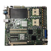
Intel SE7520AF2 Technical Product Specification (256 pages)
Brand:
Intel
| Category:
Server Board
| Size: 3.24 MB
Table of Contents
Table of Contents
5
Introduction
21
Chapter Outline
21
Server Board Use Disclaimer
22
Server Board Overview
23
Intel® Server Board SE7520AF2 SKU Options
23
Intel® Server Board SE7520AF2 Feature Set
23
Server Board Layout
25
Component Placement
25
Figure 1. Board Layout
25
Mechanical Drawing
26
Figure 2. Board Dimensions
26
ATX I/O Layout
27
Figure 3. ATX Rear IO Connectors
27
Functional Architecture
29
Figure 4. Server Board Block Diagram
29
Intel® E7520 Chipset
30
Memory Controller Hub (MCH)
30
Table 1. PCI Express* Hot-Plug LED Function Table
33
PCI-X Hub (PXH)
34
IOP332 I/O Processor
35
I/O Controller Hub (ICH5-R)
35
Table 2. PCI-X Hot-Plug LED Function Table
35
Table 3. ICH5-R GPIO Assignment
38
Processor Sub-System
39
Processor VRD
40
Reset Configuration Logic
40
Processor Module Presence Detection
40
Table 4. Processor Support Matrix
40
Gtl2006
41
Common Enabling Kit (CEK) Design Support
41
Memory Sub-System
41
Figure 5. CEK 'Passive' Component Stackup
41
Supported Memory
42
DIMM Population Rules and Supported Configurations
42
Table 5. SE7520AF2 Supported DIMM Modules
42
Figure 6. DIMM Socket Configuration
43
Single Channel Operation
44
I 2 C Bus
44
Memory Voltage Margining
44
Memory RASUM Features
44
Table 6. I C Addresses for Memory Module SMB
44
Figure 7. Four DIMM Memory Mirror Configuration
48
Figure 8. Six DIMM Memory Mirror Configuration
49
Figure 9. Eight DIMM Memory Mirror Configuration
50
I/O Sub-System
51
PCI Subsystem
51
Table 7. PCI Bus Segment Characteristics
51
Table 8. ICH5-R P32-A Configuration Ids
52
Table 9. ICH5-R P32-A Arbitration Connections
52
Table 10. PXH P64-A Configuration Ids
53
Table 11. PXH P64-B Configuration Ids
53
Table 12. PXH P64-A Arbitration Connections
54
Table 13. PHX P64-B Arbitration Connections
54
Table 14. IOP332 P64-A Configuration Ids
54
Interrupt Routing
55
Revision
55
Intel Order Number C77866-003
55
Table 15. IOP332 P64-B Configuration Ids
55
Table 16. IOP332 P64-B Arbitration Connections
55
Table 17. IOP332 P64-B Arbitration Connections
55
Table 18. PCI Interrupt Routing/Sharing
56
Table 19. Interrupt Definitions
57
Figure 10. Interrupt Routing Diagram (ICH5-R Internal)
58
Figure 11. Interrupt Routing Diagram
59
SCSI Support
60
RAID Functionality
62
Parallel ATA (PATA) Support
63
Figure 12. Intel® Portable Cache Module
63
Serial ATA (SATA) Support
64
Video Controller
65
Table 20. Intel® Server Board SE7520AF2 Video Modes
65
Table 21. Video Memory Interface
66
Network Interface Controller (NIC)
67
Figure 13. Video Controller PCI Bus Interface
67
USB 2.0 Support
68
Super I/O
68
Table 22. NIC2 Status LED
68
Table 23. Super I/O GPIO Usage Table
68
Table 24. Serial a Header Pin-Out
69
BIOS Flash
70
Configuration and Initialization
70
Memory Space
70
Figure 14. Intel® Xeon Processor Memory Address Space
71
Figure 15. DOS Compatibility Region
72
Figure 16. Extended Memory Map
74
Table 25. SMM Space Transaction Handling
75
I/O Map
76
Table 26. SMM Space Table
76
Table 27. Intel® Server Board SE7520AF2 I/O Map
76
Accessing Configuration Space
78
Figure 17. CONFIG_ADDRES Register
79
Hardware Initialization
80
Table 28. PCI Configuration Ids and Device Numbers
80
Clock Generation and Distribution
81
Table 29. Clock Generation and Distribution
81
Integrated Intel® RAID Controller SROMBU42E
83
Overview
83
Primary Integrated Intel RAID Controller SROMBU42E Features
83
Figure 18. Intel® RAID Activation Key
83
Table 30. Integrated Intel® RAID Controller SROMBU42E Features
84
Configuration on Disk
85
Array Performance Features
85
Fault Tolerance Capabilities
85
Table 31. RAID Controller SROMBU42E Array Performance
85
Table 32. RAID Controller SROMBU42E Fault Tolerance
85
RAID Software Stack
86
General RAID Features
86
RAID Level Migration
87
Fault Tolerant Features
87
Cache Options and Settings
87
Table 33. RAID Level Migration Matrix
87
Background Tasks
88
Error Handling
88
Decoding an Audible Alarm
89
Levels of RAID
89
RAID 0 - Data Striping
89
RAID 1 - Disk Mirroring/Disk Duplexing
90
RAID 5 - Data Striping with Striped Parity
90
Figure 19. RAID 0
90
Figure 20. RAID 1
90
RAID 10 - Combination of RAID 1 and RAID 0
91
RAID 50 - Combination of RAID 5 and RAID 0
91
Figure 21. RAID 5
91
Figure 22. RAID 5
91
Levels of Drive Hierarchy Within the Intel® Integrated RAID Firmware
92
Figure 23. RAID 50
92
Intel® RAID Controller Drivers
93
Intel® RAID Web Console
93
Intel® RAID BIOS Console Configuration Utility
94
Quick Configuration Steps
94
Starting the BIOS Console Utility on the Host Computer
94
Screen and Option Descriptions
95
Figure 24. Inte® RAID BIOS Console Screen
95
Table 34. Adapter Properties Menu Options
95
Configuration Mismatch Screen
98
Detailed Configuration Instructions
98
Figure 25. Adapter Selection Screen
98
Figure 26. Configuration Wizard Screen
99
Figure 27. Array Definition Screen
100
Figure 28. Logical Drive Definition
100
Finish Configuration
102
Initialize the Drive
102
Figure 29. Configuration Wizard Preview Screen
102
Figure 30. Logic Drives Screen
103
System BIOS
105
BIOS Identification String
105
Supported BIOS Features
105
Figure 31. SE7520AF2 BIOS Identification String
105
Table 35. BIOS Features
105
Processor Initialization
106
Multiple Processor Initialization
106
Mixed Processor Steppings
107
Mixed Processor Models
107
Mixed Processor Families
107
Mixed Processor Cache Sizes
107
Jumperless Processor Speed Settings
107
Microcode
108
Processor Cache
108
Hyper-Threading Technology
108
Intel Speedstep® Technology
108
Intel® Extended Memory 64 Technology (Intel® EM64T)
108
Memory Initialization
108
Memory Sizing
109
Disabling Dimms
109
Memory On-Line Sparing and Mirroring
109
ECC Memory Initialization
110
Memory Population
110
DIMM Module Capacity
110
Table 36. DIMM Population
110
Table 37. Module Capacity
110
Memory Error Handling
111
Memory Test
111
PCI Initialization
112
Scan Order
112
Resource Assignment
112
Automatic IRQ Assignment
112
Option Roms
112
PCI Apis
113
Split Option ROM
113
Dual Video
113
PCI Hot Plug Initialization
113
Table 38. PCI Express* Hot-Plug LED Function Table
115
PCI Express* Initialization
116
PCI Express* Enhanced Configuration Mechannisms
116
Legacy Universal Serial Bus (USB) Initialization
116
IDE Initialization
116
Figure 32. Enhanced Configuration Memory Address Map
116
Removable Media Initialization
117
Flash ROM
117
BIOS User Interface
117
System State Window
118
Logo/Diagnostic Window
118
Current Activity Window
118
System Diagnostic Screen
118
Static Information Display
118
Quiet Boot / OEM Splash Screen
119
5.10 BIOS Boot Popup Menu
119
5.11 BIOS Setup Utility
119
Localization
119
Console Redirection
120
Configuration Reset
120
Keyboard Commands
120
Table 39. BIOS Setup Keyboard Command Bar Options
120
Entering BIOS Setup
121
Table 40. BIOS Setup Main Menu Options
121
Table 41. BIOS Setup Advance Menu Options
122
Table 42. BIOS Setup CPU Configuration Menu Options
122
Table 43. BIOS Setup IDE Configuration Menu Options
124
Table 44. BIOS Setup, IDE Device Configuration Sub-Menu Selections
125
Table 45. BIOS Setup Floppy Configuration Sub-Menu Selections
126
Table 46. BIOS Setup Superio Configuration Sub-Menu
127
Table 47. BIOS Setup USB Configuration Sub-Menu Selections
127
Table 48. BIOS Setup, USB Mass Storage Device Configuration Sub-Menu Selections
128
Table 49. BIOS Setup PCI Configuration Sub-Menu Selections
128
Table 50. BIOS Setup, Memory Configuration Sub-Menu Selections
129
Table 51. BIOS Setup, Boot Menu Selections
131
Table 52. BIOS Setup, Boot Settings Configuration Sub-Menu Selections
131
Table 53. BIOS Setup, Boot Device Priority Sub-Menu Selections
132
Table 54. BIOS Setup, Hard Disk Drive Sub-Menu Selections
132
Table 55. BIOS Setup, Removable Drives Sub-Menu Selections
132
Table 56. BIOS Setup, ATAPI CDROM Drives Sub-Menu Selections
132
Table 57. BIOS Setup, Security Menu Options
133
Table 58. BIOS Setup, Server Menu Selections
134
Table 59. BIOS Setup, System Management Sub-Menu Selections
135
Table 60. BIOS Setup Serial Console Features Sub-Menu Selections
136
Table 61. BIOS Setup, Event Log Configuration Sub-Menu Selections
136
5.12 Flash Architecture and Flash Update Utility
137
Table 62. BIOS Setup, Exit Menu Selections
137
5.13 Rolling BIOS and On-Line Updates
138
5.14 Flash Update Utility
138
Flash BIOS
138
User Binary Area
140
Recovery Mode
140
Update OEM Logo
141
5.15 OEM Binary
142
Scan Point Definitions
144
Table 63. Scan Point Definitions
144
Format of the OEM Binary Structure
145
5.16 Quiet Boot / OEM Splash Screen
145
Microsoft* Windows* Compatibility
145
Table 64: Format of OEM Binary Structure
145
Operating System Boot, Sleep, and Wake
146
Advanced Configuration and Power Interface (ACPI)
146
Sleep and Wake Functionality
147
On to off (Operating System-Present) or Operating System to Sleep
147
Sleep to on (ACPI)
148
System Sleep States
148
Table 65. Supported Wake Events
148
Platform Management
149
Management Architecture Overview
149
Tiered Server Management Model
149
Table 66. Tiered Platform Management Feature Overview
150
Table 67. Power and Reset Control
151
Table 68. Secure Mode Button Actions
151
Table 69. Memory RAS Feature Support by SM Tier
151
Standby
153
IPMI Messaging, Commands, and Abstractions
154
IPMI 'Sensor Model
154
Private Management Bus
155
Management Controllers
156
Onboard Platform Instrumentation Management Features and Functionality
158
Mbmc Self-Test
159
Smbus Interfaces
159
External Interface to Mbmc
159
Messaging Interfaces
160
Table 70. Supported Channel Assigments
161
Direct Platform Control (IPMI over LAN)
162
Table 71. LAN Channel Capacity
162
Wake on LAN / Power on LAN and Magic Packet Support
164
Table 72. LAN Channel Specifications
164
Watchdog Timer
165
System Event Log (SEL)
165
Sensor Data Record (SDR) Repository
166
Event Message Reception
166
Event Filtering and Alerting
166
Table 73. PEF Action Priorities
167
Table 74. Mbmc Factory Default Event Filters
167
NMI Generation
169
Platform Management Interconnects
170
Power Supply Interface Signals
170
System Reset Control
171
Table 75. Power Control Initiators
171
Table 76. System Reset Sources and Actions
171
Temperature-Based Fan Speed Control
172
Front Panel Control
172
Table 77. Chassis ID Leds
174
Table 78. Fault/Status LED
174
Fru Information
175
FRU Information
176
Sensors
176
Sensor Type Codes
176
Table 79. Mbmc Built-In Sensors
177
Table 80. Intel® Server Board SE7520AF2 Sensors for ob Platform Instrumentation Management
178
Table 81. Platform Sensors for the Intel® Management Module
180
Error Reporting and Handling
189
Fault Resilient Booting (FRB)
189
FRB-3 - BSP Reset Failures
189
FRB-2 - BSP POST Failures
189
FRB-1 - BSP Self-Test Failures
190
OS Watchdog Timer: Operating System Load Failures
190
AP Failures
191
Treatment of Failed Processors
191
Error Logging
192
Error Sources and Types
192
SMI Handler
192
Table 82. Memory Error Events
194
Table 83. Examples of Event Data Field Contents for Memory Errors
195
Table 84. PCI Error Events
195
Table 85. Event Data Field Contents for PCI Errors
196
Table 86. FRB-2 Error Events
196
BIOS Generated IPMI Events
197
Table 87. Event Data Field Contents for FRB-2 Errors
197
Table 88. BIOS Generated IPMI Events
197
Single Bit ECC Error Throttling Prevention
198
Error Messages and Error Codes
199
POST Progress Codes and Messages
199
Table 89. POST Progress Code LED Example
199
Table 90. POST Code Checkpoints
200
Table 91. Bootblock Initialization Code Checkpoints
202
Table 92. Bootblock Recovery Code Checkpoints
203
Table 93. DIM Code Checkpoints
204
Table 94. ACPI Runtime Checkpoints
205
BIOS Messages
206
Table 95. Memory BIOS Messages
206
Table 96. Boot BIOS Messages
206
Table 97. Storage Device BIOS Messages
207
Table 98. Virus Related BIOS Messages
209
Table 99. System Configuration BIOS Messages
210
Table 100. CMOS BIOS Messages
211
Table 101. Miscellaneous BIOS Messages
211
Table 102. USB BIOS Error Messages
211
POST Error Messages and Handling
212
Table 103. SMBIOS BIOS Error Messages
212
Table 104. POST Error Messages and Handling
212
Table 105. Management Module POST Error Codes and Messages
214
Boot Block Error Beep Codes
215
POST Error Beep Codes
215
Table 106. Bootblock Error Beep Codes
215
Table 107. POST Error Beep Codes
215
POST Error Pause" Option
216
Table 108. Troubleshooting BIOS Beep Codes
216
Connectors, Headers and Jumpers
217
Board Connector Information
217
Table 109. Board Connector Matrix
217
Main Power Connector
218
Table 110. Power Connector Pin-Out (J9C1)
218
Table 111. Power Supply Signal Connector (J9B1)
218
Table 112. 12V Power Connector (J9E1)
218
Main Memory Module Connector
219
Table 113. DIMM Connectors (J9D1, J9D2, J8D2, J8D3, J7D3, J8D1, J7D1, J7D2)
219
RAID Memory Module Connector
220
Table 114. RAID DIMM Connector (J1D5)
220
Processor Socket
221
Table 115. Socket 604 Processor Socket Pinout (J8H1, J6H1)
221
Table 116. IMM Connector Pin-Out (J3J1)
224
System Management Headers
225
Intel Management Module Connector
225
ICMB Header
227
Table 117. ICMB Header Pin-Out (J1A1)
227
IPMB Header
228
OEM RMC Header
228
HSBP Header
228
Table 118. IPMB Header Pin-Out (J1G1)
228
Table 119. IPMB Header Pin-Out (J1B2)
228
Table 120. HSBP Header Pin-Out (J1K3, J1K2)
228
PCI Slot Connector
229
Table 121. PCI Slot Characteristics
229
Table 122. Slot 1 and 5 PCI-X 64Bit 3.3V Pin-Out (J1D4, J4D1)
229
Table 123. Slot 3 and 4 PCI Express* Pin-Out (J2C1, J3C1)
230
Table 124. Slot 6 PCI-X 64-Bit 3.3V Pin-Out (J4D2, Riser Capable)
231
Front Panel Connectors
232
Table 125. Front Panel 34-Pin Header Pin-Out (J1E1)
232
VGA Connector
233
8.10 SCSI Connector
233
Table 126. VGA Connector Pin-Out (J8A1)
233
Table 127. 68-Pin SCSI Connector Pin-Out (J1H1, J1F1)
233
8.11 NIC Connectors
234
Table 128. NIC1 and NIC2 1.0Gb RJ45 Connector Pin-Out (J6A1)
234
8.12 ATA Connector
235
8.13 USB Connector
235
Table 129. ATA-100 40-Pin Connector Pin-Out (J3K1)
235
Table 130. USB Connectors Pin-Out (J9A2)
235
8.14 Floppy Connector
236
Table 131. Optional USB Connection Header Pin-Out (J1K4)
236
Table 132. Legacy 34-Pin Floppy Connector Pin-Out (J3K2)
236
Table 133. Rear DB-9 Serial a Port Pin-Out (J8A1)
237
Table 134. 9-Pin Header Serial B Port Pin-Out (J1B1)
237
Serial Port Connector
238
8.16 Keyboard and Mouse Connector
238
Table 135. Keyboard and Mouse PS2 Connector Pin-Out (J9A1)
238
Table 136. 3-Pin CPU Fan Headers Pin-Out (J6F1, J5F1)
238
Table 137. 3 Pin System Fan Headers Pin-Out (J5A2, J5A1)
238
Table 138. 3+2 Pin System Fan Headers Pin-Out (J2J3+J2K3, J2J2+J2K1)
238
Fan Headers
239
Table 139. 6-Pin System Fan Headers Pin-Out (J2K4, J2K2)
239
Configuration Jumpers
240
System Recovery and Update Jumpers
240
Table 140. Configuration Jumper Options
240
Rolling BIOS Bank Selection Jumper
241
Table 141. BIOS Bank Jumper Option
241
General Specifications
242
10.2 Absolute Maximum Ratings
242
Table 142. Absolute Maximum Ratings
242
Table 143. Intel® Xeon™ Processor DP TDP Guidelines
242
Processor Power Support
243
Table 144. SE7520AF2 Power Budget
243
Table 145. SE7520AF2 Power Supply Voltage Specification
243
SE7520AF2 Power Budget
244
Power Supply Specifications
244
Power Timing
244
Table 146. Voltage Timing Parameters
244
Table 147. Turn on / off Timing
244
Voltage Recovery Timing Specifications
246
Table 148. Transient Load Requirements
246
Product Regulatory Compliance
249
Product Safety Compliance
249
Product EMC Compliance
249
Product Regulatory Compliance Markings
249
11.2 Electromagnetic Compatibility Notices
249
Fcc (Usa)
249
Industry Canada (ICES-003)
249
Europe (CE Declaration of Conformity)
249
Australian Communications Authority (ACA) (C-Tick Declaration of Conformity)251
250
Ministry of Economic Development (New Zealand) Declaration of Conformity
250
Korean RRL Compliance
250
BSMI (Taiwan)
250
11.3 Replacing the Back-Up Battery
250
Integration and Usage Tips
252
Glossary
253
Reference Specifications and Documents
256
Advertisement
Intel SE7520AF2 User Manual (58 pages)
User Guide
Brand:
Intel
| Category:
Server Board
| Size: 0.9 MB
Table of Contents
Additional Information and Software
4
Safety Information
5
Safety Cautions
7
Table of Contents
10
1 Server Board Features
13
Figure 1. Intel ® Server Board SE7520AF2
13
Table 1. Server Board Features
14
Connector and Header Locations
16
Figure 2. Server Board Connector and Header Locations
16
Configuration Jumpers
17
Figure 3. Configuration Jumper Location
17
Table 2. Configuration Jumper [J1D1]
17
Back Panel Connectors
18
Figure 4. Back Panel Connectors
18
Table 3. NIC Leds
18
Hardware Requirements
19
Figure 5. Four DIMM Memory Mirroring
20
Figure 6. Six DIMM Memory Mirroring
20
Figure 7. Eight DIMM Memory Mirroring
20
Power Supply
21
2 Hardware Installations and Upgrades
22
Before You Begin
22
Tools and Supplies Needed
22
Installing and Removing Memory
22
Installing Dimms
23
Figure 8. Installing Memory
23
Removing Dimms
24
Installing or Replacing the Processor
24
Installing the Processor
25
Figure 9. Opening Socket Lever
25
Figure 10. Inserting Processor
25
Figure 11. Closing Socket Lever
26
Removing a Processor
27
Figure 12. Installing Heat Sink
27
Installing or Removing a PCI Card
28
Figure 13. Removing the PCI Air Duct
28
Figure 14. PCI Hot-Plug Leds at Rear of Chassis
29
Figure 15. Installing a PCI Card
30
Replacing the Backup Battery
31
Figure 16. Replacing the Backup Battery
32
3 Server Utilities
33
Using the BIOS Setup Utility
33
Starting Setup
33
If You Cannot Access Setup
33
Setup Menus
33
Table 4. Keyboard Commands
34
4 Upgrading the BIOS
35
Preparing for the Upgrade
35
Upgrading the BIOS
36
Clearing the Password
36
Figure 17. Password Clear Jumper
36
Clearing the CMOS
37
Figure 18. Clearing the CMOS Jumper
37
5 Troubleshooting
38
Resetting the System
38
Problems Following Initial System Installation
38
First Steps Checklist
38
Table 5. Resetting the System
38
Hardware Diagnostic Testing
39
Verifying Proper Operation of Key System Lights
40
Confirming Loading of the Operating System
40
Specific Problems and Corrective Actions
40
Power Light Does Not Light
40
No Characters Appear on Screen
41
Characters Are Distorted or Incorrect
42
System Cooling Fans Do Not Rotate Properly
42
Diskette Drive Activity Light Does Not Light
42
CD-ROM Drive or DVD-ROM Drive Activity Light Does Not Light
43
Cannot Connect to a Server
43
Problems with Network
43
System Boots When Installing PCI Card
44
Problems with Newly Installed Application Software
44
Problems with Application Software that Ran Correctly Earlier
44
Devices Are Not Recognized under Device Manager
45
System)
45
Hard Drive(S) Are Not Recognized
45
Bootable CD-ROM Is Not Detected
45
LED Information
46
Table 6. LED Descriptions
46
BIOS POST Beep Codes
47
Boot Block Error Beep Codes
47
Table 7. Boot Block Error Beep Codes
47
POST Error Beep Codes
48
BIOS Recovery Beep Codes
48
Table 8. POST Error Beep Codes
48
Table 9. Troubleshooting BIOS Beep Codes
48
Regulatory and Certification Information
49
Product Regulatory Compliance
49
Product Safety Compliance
49
Product EMC Compliance - Class a Compliance
49
Certifications / Registrations / Declarations
50
Product Regulatory Compliance Markings
51
Electromagnetic Compatibility Notices
51
FCC Verification Statement (USA)
51
ICES-003 (Canada)
52
Europe (CE Declaration of Conformity)
52
VCCI (Japan)
52
BSMI (Taiwan)
53
RRL (Korea)
53
CNCA (CCC-China)
53
Getting Help
54
World Wide Web
54
Intel Server Issue Report Form
56
Intel SE7520AF2 Operating Manual (34 pages)
Brand:
Intel
| Category:
Server Board
| Size: 0.17 MB
Table of Contents
Table of Contents
3
1 Introduction
7
Test Overview
7
Basic Installation Testing
7
Adapter / Peripheral Compatibility and Stress Testing
8
Pass/Fail Test Criteria
9
2 Intel Server Board SE7520AF2 Base System Configurations
10
3 Supported Operating Systems
11
Operating System Certifications
12
4 Adapters and Peripherals
13
Pci Scsi
15
Raid
16
PCI Fibre Channel
17
Pci Nic
18
Modems
20
Keyboard and Mouse Devices
20
CDROM Drives
21
DVD Drives
21
Tape Drives
22
4.10 Removable Drives
23
4.11 Kvm
24
4.12 Graphic
24
5 Hard Disk Drives
26
USB Hard Disks Drives
27
ATA Hard Disks Drives
27
SATA Hard Disks Drives
27
SCSI Hard Disks Drives
29
6 Installation Guidelines
32
Windows 2000 Advanced Sever Recognizes Only 4 GB of Memory
32
Potential Data Corruption Manifested under Suse
32
Tape Drive Shown as if 8 Tapes Are Installed
32
Novell Netware* 6.5 Emulex* LP9802DC Driver Fails to Load
33
Sony* Tape Drives Fully Supportive with SE7520AF2 BIOS P07
33
Netware* 6.5 Service Pack 4 Not Bootable with Certain LAN Adapters Present in PCI Slot #5
34
Advertisement
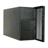
Intel SE7520AF2 Spares Parts List & Configuration Manual (13 pages)
Server Board, Server Chassis & Server Platform
Brand:
Intel
| Category:
Server Board
| Size: 0.32 MB
Table of Contents
Table of Contents
2
Production Configurations
3
Overview
3
Production Boards and KDK (Building Blocks) Ordering Process
3
SC5300AF2 Integrated SKU Description
5
Production Boards and KDK Descriptions
6
Production Order Code Details
8
Production Integrated Skus
8
Production Boards
8
Production Chassis
9
Production Board Spares & Accessories
9
Production Chassis Accessories
10
Production Chassis Spares (Field Replaceable Units)
11
Existing Production Spares & Accessories
12
Intel RAID Options
12
Advertisement
Related Products
Intel SE7520AF
Intel SE7520BD2
Intel SE7520BD2SATAD2
Intel SE7520BD2SCSI - E7520 DP PGA604 MAX-12GB
Intel SE7520BD2SCSID2
Intel SE7520BD2VD2
Intel SE7520JR2SCSID1 - Server Board SE7520JR2
Intel SE7520JR2SCSID2
Intel SE7520BD2-D2
Intel SE7525RP2
Intel Categories
Motherboard
Computer Hardware
Server
Server Board
Desktop
More Intel Manuals
Login
Sign In
OR
Sign in with Facebook
Sign in with Google
Upload manual
Upload from disk
Upload from URL