Sign In
Upload
Manuals
Brands
Intel Manuals
Server Board
SE7520BD2
Intel SE7520BD2 Manuals
Manuals and User Guides for Intel SE7520BD2. We have
4
Intel SE7520BD2 manuals available for free PDF download: Technical Product Specification, User Manual, Tested Hardware And Operationg System List
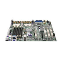
Intel SE7520BD2 Technical Product Specification (179 pages)
Brand:
Intel
| Category:
Server Board
| Size: 2.16 MB
Table of Contents
Table of Contents
3
1 Introduction
13
Purpose
13
Audience
13
Document Outline
13
Additional Technical Documentation
13
Board Usage Disclaimer
14
2 Product Overview
15
Server Board Feature Set
15
Server Board Illustration
16
Figure 1. Top Side View of the Intel® Server Board SE7520BD2
16
Mechanical Drawing
17
Figure 2. Intel Server Board SE7520BD2 Server Board Mechanical Drawing
17
Server Board Layout
18
Figure 3. Intel® Server Board SE7520BD2 SCSI System Block Diagram
18
Figure 4. Intel® Server Board SE7520BD2 SATA System Block Diagram
19
Identifying the Version of an Intel® Server Board
20
Chipset Overview
20
Figure 5. Intel® Server Board SE7520BD2-V System Block Diagram
20
Front Side Bus (FSB)
21
MCH Memory Sub-System Overview
21
Memory Controller Hub (MCH)
21
Hub Interface
22
PCI Express (Pcie)
22
Processor Subsystem Detail
22
Table 1. Processor Support Matrix
23
Multiple Processor Initialization
24
Processor VRD
24
Common Enabling Kit (CEK) Design Support
25
Gtl2006
25
Processor Module Presence Detection
25
Reset Configuration Logic
25
Memory Sub-System Detail
26
Figure 6. Intel® Server Board SE7520BD2 Memory/Cpu Block Diagram
26
Table 2. Memory Bank Labels
26
DDR-1 266 Memory
27
Figure 7. DIMM Socket Configuration
27
Table 3. DDR-1 266-Mhz Memory Population
27
Ecc
28
Single-Channel Operation
28
Table 4. DDR-1 333-Mhz Memory Population
28
Figure 8. Memory Subsystem
30
C Bus Detail
31
PCI Sub-System Detail
31
ICH5-R PCI Interface
31
Table 5. I 2 C Addresses for Memory Module SMB
31
Table 6. GPIO on the Intel® Server Board SE7520BD2
34
Pxh
35
Table 7. Slot 6 PCI-X Pin-Out
36
Ultra-320 SCSI Controller
38
Modular RAID on Baseboard (MROMB)
38
Figure 9. MROMB Implementation
39
Table 8. Signal Description/Functionality
39
Table 9. Quick Switch MUX Functionality
39
IO Sub-System Detail
40
Server I/O
40
Intel® 3-Volt Advanced+ Boot Block Flash Memory
40
Video Controller
41
Clock Generation and Distribution
41
CK409 Clock Generator
41
DB800 Differential Buffer
42
3 BIOS Architecture
43
BIOS Functionality
43
Support for BIOS Features
43
BIOS Identification String
47
Hardware Requiring BIOS Support
48
Bios Post
48
User Interface
48
BIOS Setup Utility
49
Entering BIOS Setup
49
Keyboard Commands
50
Table 10. BIOS Setup Utility Keyboard Commands
50
Menu Selection
51
Main Menu
51
Table 11. BIOS Setup, Main Menu Options
51
Advanced Menu
52
Table 12. BIOS Setup, Advanced Menu Options
52
Table 13. BIOS Setup, Processor Configuration Sub-Menu Options
52
Table 14. BIOS Setup IDE Configuration Menu Options
54
Table 15. Mixed P-ATA-S-ATA Configuration with Only Primary P-ATA
55
Table 16. BIOS Setup, IDE Device Configuration Sub-Menu Selections
55
Table 17. BIOS Setup, Floppy Configuration Sub-Menu Selections
56
Table 18. BIOS Setup, Super I/O Configuration Sub-Menu
57
Table 19. BIOS Setup, USB Configuration Sub-Menu Selections
57
Table 20. BIOS Setup, USB Mass Storage Device Configuration Sub-Menu Selections
58
Table 21. BIOS Setup, PCI Configuration Sub-Menu Selections
58
Table 22. BIOS Setup, Memory Configuration Sub-Menu Selections
60
Boot Menu
61
Table 23. BIOS Setup, Boot Menu Selections
61
Table 24. BIOS Setup, Boot Settings Configuration Sub-Menu Selections
62
Table 25. BIOS Setup, Boot Device Priority Sub-Menu Selections
62
Table 26. BIOS Setup, Hard Disk Drive Sub-Menu Selections
62
Security Menu
63
Table 27. BIOS Setup, Removable Drives Sub-Menu Selections
63
Table 28. BIOS Setup, CD/DVD Drives Sub-Menu Selections
63
Table 29. BIOS Setup, Security Menu Options
63
Server Menu
65
Table 30. BIOS Setup, Server Menu Selections
65
Table 31. BIOS Setup, System Management Sub-Menu Selections
66
Table 32. BIOS Setup, Serial Console Features Sub-Menu Selections
67
Table 33. BIOS Setup, Event Log Configuration Sub-Menu Selections
67
Exit Menu
68
Other BIOS Configuration Utilities
68
Logo Update Utility
68
Flash Update Utility
68
Table 34. BIOS Setup, Exit Menu Selections
68
Localization Details
69
Flash Architecture and Flash Update Utility
70
Rolling BIOS and On-Line Updates
70
Flash Update Utility
70
User Binary Area
72
Recovery Mode
72
Update OEM Logo
74
OEM Binary
75
PCI Numeration
77
ACPI Runtime Checkpoints
78
Table 35. ACPI Runtime Checkpoints
78
4 Platform Management Architecture
79
Management Architecture Overview
79
Tiered Server Management Model
79
Table 36. Tiered Platform Management Feature Overview
79
Table 37. Power and Reset Control
80
Table 38. Secure Mode Button Actions
81
Table 39. Memory RAS Feature Support by Server Management Tier
81
Standby
82
Figure 10. Block Diagram of Platform Managment Architecture
82
IPMI Messaging, Commands, and Abstractions XXX
83
IPMI 'Sensor Model
83
Private Management Buses
84
Management Controllers
84
Table 40. Mbmc Built-In Sensors
87
Table 41. Onboard Platform Instrumentaion Using the Mbmc
88
Table 42. Platform Instrumentation Sensors Using the Intel® Management Module
90
Essentials Management Features and Functionality
96
Overview of Mbmc
96
Figure 11. Mbmc in a Server Management System
96
Mbmc Self-Test
97
Smbus Interfaces
97
External Interface to Mbmc
97
Messaging Interfaces
98
Figure 12. External Interfaces to Mbmc
98
Table 43. Supported Channel Assigments
99
Direct Platform Control (IPMI over LAN)
100
Table 44. LAN Channel Capacity
100
Figure 13. IPMI-Over-LAN
101
Wake on LAN / Power on LAN and Magic Packet Support
102
Table 45. LAN Channel Specifications
102
Watchdog Timer
103
System Event Log (SEL)
103
Sensor Data Record (SDR) Repository
104
Event Message Reception
104
Event Filtering and Alerting
104
Table 46. PEF Action Priorities
105
Table 47. Mbmc Factory Default Event Filters
105
NMI Generation
107
SMI Generation
107
Platform Management Interconnects
107
Power Supply Interface Signals
107
Figure 14. Power Supply Control Signals
108
System Reset Control
109
Table 48. Power Control Initiators
109
Fan Speed Control
110
Front Panel Control
110
Table 49. System Reset Sources and Actions
110
Table 50. Chassis ID Leds
112
Table 51. Fault/Status LED
112
FRU Information
114
Sensors
114
Sensor Type Codes
114
Table 52. Mbmc Built-In Sensors
115
Table 53. Intel® Server Board SE7520BD2 Platform Sensors for Essentials Management
116
Server Management Block Diagram
118
Management Buses and Connectors
118
SIO Keyboard and Mouse
119
PS2 Keyboard and Mouse
119
Fast Management Link (FML)
119
Lpc/Keyboard Controller Style Ports
120
Usb
120
C Interfaces
121
16550*-Style Uarts
121
Interrupts
122
GPIO Pins and LED Drivers
122
Sleep States Supported
122
Wake Events
123
AC Power Failure Recovery
123
PCI Power Management Support
123
System Status Indicators/Leds
124
Front Panel
124
Figure 15. Front Panel Pinout
125
Table 54. Front Panel Color Attributes
126
5 Error Reporting and Handling
127
Error Propagation
127
Fault Resilient Booting (FRB)
127
BSP Reset Failures
127
BSP POST Failures
127
FRB-3 – BSP Reset Failures
127
FRB-2 – BSP POST Failures
127
FRB-1 - BSP Self-Test Failures
128
OS Boot Timer - os Load Failures
128
Application Processor (AP) Failures
128
Treatment of Failed Processors
128
Error Messages and Error Codes
129
POST Error Codes and Messages
129
Table 55. Error Codes and Messages
129
POST Error Beep Codes
131
Table 56. Error Codes Sent to Management Module
131
Checkpoints
132
Table 57. POST Error Beep Codes
132
Table 58. Troubleshooting BIOS Beep Codes
132
Table 59. POST Progress Code LED Example
133
Table 60. Memory Error Codes
133
Error Logging
134
Error Sources and Types
134
SMI Handler
135
Logging Format Conventions
136
Table 61. Memory Error Events
136
Table 62. Examples of Event Data Field Contents for Memory Errors
137
Table 63. PCI Error Events
138
Table 64. Examples of Event Data Field Contents for PCI Errors
138
Table 65. FRB-2 Error Events
139
Table 66. Examples of Event Data Field Contents for FRB-2 Errors
139
POST Code Checkpoints
140
Table 67. POST Code Checkpoints
140
Boot Block Initialization Code Checkpoints
142
Table 68. Boot Block Initialization Code Checkpoints
142
Boot Block Recovery Code Checkpoint
143
Table 69. Boot Block Recovery Code Checkpoint
143
Table 70. Boot Block Recovery Beep Code
143
DIM Code Checkpoints
144
Single-Bit ECC Error Throttling Prevention
144
Table 71. DIM Code Checkpoints
144
Reliability, Availability and Serviceability (RAS) Features
145
Memory RAS Features
145
PCI Express
145
RAS Features of FSB
146
Pci-X
146
RMC Connector Utilization
146
Rolling BIOS
147
6 Connector Pin-Outs and Jumper Blocks
148
Board Connector Pin-Outs
148
Table 72. Board Connector Matrix
148
Table 73. Test Support Connector
148
Table 74. OEM RMC 8-Pin (Remote Management Card Support)
149
Table 75. EPS12V 2X12 Connector
149
Table 76. EPS12V 2X4 Connector
150
Table 77. EPS12V 1X5 Connector
150
Table 78. Primary IDE Connector
150
Table 79. Front Panel Connector
151
Table 80. USB Front Connector
151
Table 81. USB Rear Connector
151
Table 82. SATA Connector
152
Table 83. Battery Holder
152
Table 84. Piezo* Speaker
152
Table 85. SCSI LED Connector
152
Table 86. PLL Multiplier Selection Bit 0
152
Table 87. PLL Multiplier Selection Bit 1
152
Table 88. Fan 1 and Fan 2 (3 Pin + 2 Pin)
153
Table 89. Fan 3 and Fan 4
153
Table 90. Fan 5 and Fan 6
153
Board Jumper Blocks
154
Rolling BIOS Bank Selection Jumper
154
BIOS Recovery
154
Password Clear
154
Table 91. BIOS Bank Selection Jumper
154
Table 92. BIOS Recovery Jumper Setting
154
Table 93. Password Clear Jumper Setting
154
CMOS Clear
155
Figure 16. Jumper Locations
155
Table 94. CMOS Clear Jumper Setting
155
7 Environmental Specifications
156
Environmental Specifications and Cooling Requirements
156
Power Supply Requirements
157
Baseboard Power Budget
157
Table 95. Baseboard Power Budget
157
Voltages Supported
160
Table 96. Intel® Server Board SE7520BD2 Board Voltage Table
160
Standby Powered Device Map
161
System Reset Block Diagram
161
Figure 17. Reset and Powergood Timings
162
Figure 18. Intel® Server Board SE7520BD2 Power Sequencing Diagram
163
Airflow Requirements
164
Board Thermal Map
164
Board Usage Disclaimer
164
Board Level Calculated MTBF Data
164
Intel Speedstep® Technology
164
Intel® Extended Memory 64 Technology
164
Product Regulatory Compliance
164
Product Safety Compliance
164
Product EMC Compliance
165
Mandatory/Standard: Certifications, Registration, Declarations
165
Product Regulatory Compliance Markings
166
Electromagnetic Compatibility Notices
166
Replacing the Back up Battery
166
8 Other Useful Information
168
Platform Confidence Test (PCT)
168
Appendix A - Known Errata
169
Glossary
177
Reference Documents
178
Advertisement
Intel SE7520BD2 User Manual (64 pages)
User Guide
Brand:
Intel
| Category:
Server Board
| Size: 0.53 MB
Table of Contents
About this Manual
3
Additional Information and Software
4
Product Accessories
4
Safety Information
5
Table of Contents
9
1 Server Board Features
13
Figure 1. Intel ® Server Board SE7520BD2
13
Table 1. Server Board Varieties
14
Table 2. Server Board Features
17
Connector and Header Locations
18
Product Codes SE7520BD2, SE7520BD2SCSI, SE7520BD2V
18
Figure 2. Product Codes SE7520BD2, SE7520BD2SCSI, and SE7520BD2V Connector and Header Locations
19
Product Codes SE7520BD2SCSID2, SE7520BD2VD2, SE7520BD2SATAD2
20
Figure 3. Product Codes SE7520BD2SCSID2, SE7520BD2VD2, and SE7520BD2SATAD2 Connector and Header Locations
21
Configuration Jumpers
22
Figure 4. Configuration Jumper Location
22
Table 3. Configuration Jumpers
22
Back Panel Connectors
23
Figure 5. Back Panel Connectors
23
Table 4. NIC Leds
23
Hardware Requirements
24
Server Chassis
24
Processor
24
Table 5. Intel® Server Chassis Supported for each Server Board SE7520BD2 Product Code
24
Memory
25
Power Supply
27
2 Hardware Installations and Upgrades
28
Before You Begin
28
Tools and Supplies Needed
28
Installing and Removing Memory
28
Installing Dimms
29
Figure 6. Installing Memory
29
Removing Dimms
30
Installing or Replacing the Processor
30
Installing the Processor
31
Figure 7. Opening Socket Lever
31
Figure 8. Inserting Processor
31
Figure 9. Closing Socket Lever
32
Figure 10. Installing the Heat Sink
33
Removing a Processor
34
Installing or Removing a PCI Card
34
Replacing the Backup Battery
35
Figure 11. Replacing the Backup Battery
36
3 Server Utilities
37
Using the BIOS Setup Utility
37
Starting Setup
37
If You Cannot Access Setup
37
Setup Menus
37
Table 6. Keyboard Commands
38
Upgrading the BIOS
39
Preparing for the Upgrade
39
Preparing Media and Performing the BIOS Upgrade
40
Crisis Recovery Diskette
41
Recovering the BIOS
42
Recovering the BIOS with the Crisis Recovery Diskette
42
Figure 12. Recovery Boot Jumper
43
Clearing the Password
44
Figure 13. Password Clear Jumper
44
Clearing the CMOS
45
Figure 14. Clear CMOS Jumper
45
4 Troubleshooting
46
Resetting the System
46
Problems Following Initial System Installation
46
First Steps Checklist
46
Hardware Diagnostic Testing
47
Confirming Loading of the Operating System
48
Specific Problems and Corrective Actions
48
Power Light Does Not Light
48
No Characters Appear on Screen
49
Characters Are Distorted or Incorrect
50
System Cooling Fans Do Not Rotate Properly
50
Diskette Drive Activity Light Does Not Light
50
CD-ROM Drive or DVD-ROM Drive Activity Light Does Not Light
51
Cannot Connect to a Server
51
Problems with Network
51
System Boots When Installing PCI Card
52
Problems with Newly Installed Application Software
52
Problems with Application Software that Ran Correctly Earlier
52
Devices Are Not Recognized under Device Manager (Windows* Operating System)
53
Hard Drive(S) Are Not Recognized
53
Bootable CD-ROM Is Not Detected
53
LED Information
53
BIOS POST Beep Codes
54
Boot Block Error Beep Codes
54
POST Error Beep Codes
54
Table 7. Boot Block Error Beep Codes
54
Table 8. POST Error Beep Codes
54
Table 9. BIOS Beep Codes
55
Regulatory and Compliance Information
56
Product Regulatory Compliance
56
Product Safety Compliance
56
Product EMC Compliance - Class a Compliance
56
Certifications/Registrations/Declarations
57
Product Regulatory Compliance Markings
57
Table 10. Product Certification Markings
57
Electromagnetic Compatibility Notices
58
Fcc (Usa)
58
Industry Canada (ICES-003)
59
Europe (CE Declaration of Conformity)
59
Taiwan Declaration of Conformity (BSMI)
59
Korean Compliance (RRL)
59
Getting Help
60
Intel Server Issue Report Form
62
Intel SE7520BD2 User Manual (59 pages)
Brand:
Intel
| Category:
Server Board
| Size: 0.52 MB
Table of Contents
Safety Cautions
7
Table of Contents
11
1 Server Board Features
15
Figure 1. Intel ® Server Board SE7520BD2
16
Table 1. Server Board Features
16
Connector and Header Locations
18
Figure 2. Intel® Server Board SE7520BD2 Connector and Header Locations
18
Configuration Jumpers
19
Figure 3. Configuration Jumper Location
19
Table 2. Configuration Jumpers
19
Back Panel Connectors
20
Figure 4. Back Panel Connectors
20
Table 3. NIC Leds
20
Hardware Requirements
21
Power Supply
22
2 Hardware Installations and Upgrades
23
Before You Begin
23
Tools and Supplies Needed
23
Installing and Removing Memory
23
Installing Dimms
23
Figure 5. Installing Memory
24
Removing Dimms
25
Installing or Replacing the Processor
25
Installing the Processor
25
Figure 6. Opening Socket Lever
25
Figure 7. Inserting Processor
26
Figure 8. Closing Socket Lever
26
Figure 9. Installing the Heat Sink
27
Removing a Processor
28
Installing or Removing a PCI Card
28
Replacing the Backup Battery
29
Figure 10. Replacing the Backup Battery
30
3 Server Utilities
31
Using the BIOS Setup Utility
31
Starting Setup
31
If You Cannot Access Setup
31
Setup Menus
31
Upgrading the BIOS
32
Table 4. Keyboard Commands
32
Preparing for the Upgrade
33
Preparing Media and Performing the BIOS Upgrade
33
Changing the Bios Language
35
Crisis Recovery Diskette
35
Recovering the BIOS
35
Recovering the BIOS with the Crisis Recovery Diskette
36
Figure 11. Recovery Boot Jumper
37
Clearing the Password
38
Figure 12. Password Clear Jumper
38
Clearing the CMOS
39
Figure 13. Clear CMOS Jumper
39
4 Troubleshooting
40
Resetting the System
40
Problems Following Initial System Installation
40
First Steps Checklist
40
Hardware Diagnostic Testing
41
Confirming Loading of the Operating System
42
Verifying Proper Operation of Key System Lights
42
Specific Problems and Corrective Actions
42
Power Light Does Not Light
42
No Characters Appear on Screen
43
Characters Are Distorted or Incorrect
44
System Cooling Fans Do Not Rotate Properly
44
Diskette Drive Activity Light Does Not Light
44
CD-ROM Drive or DVD-ROM Drive Activity Light Does Not Light
45
Cannot Connect to a Server
45
Problems with Network
45
System Boots When Installing PCI Card
46
Problems with Newly Installed Application Software
46
Problems with Application Software that Ran Correctly Earlier
46
Devices Are Not Recognized under Device Manager
47
System)
47
Hard Drive(S) Are Not Recognized
47
Bootable CD-ROM Is Not Detected
47
LED Information
47
BIOS POST Beep Codes
48
Boot Block Error Beep Codes
48
Table 5. Boot Block Error Beep Codes
48
POST Error Beep Codes
49
Table 6. POST Error Beep Codes
49
Table 7. Troubleshooting BIOS Beep Codes
49
Regulatory and Compliance Information
51
Product Regulatory Compliance
51
Product Safety Compliance
51
Product EMC Compliance - Class a Compliance
51
Certifications/Registrations/Declarations
52
Product Regulatory Compliance Markings
52
Table 8. Product Certification Markings
52
Electromagnetic Compatibility Notices
53
Fcc (Usa)
53
Industry Canada (ICES-003)
53
Europe (CE Declaration of Conformity)
54
Taiwan Declaration of Conformity (BSMI)
54
Korean Compliance (RRL)
54
Getting Help
55
World Wide Web
55
Intel® Server Issue Report Form
57
Advertisement
Intel SE7520BD2 Tested Hardware And Operationg System List (27 pages)
Brand:
Intel
| Category:
Server Board
| Size: 0.14 MB
Table of Contents
Table of Contents
4
1 Introduction
5
Test Overview
5
Basic Installation Testing
5
Adapter / Peripheral Compatibility and Stress Testing
6
Pass/Fail Test Criteria
7
2 Intel® Server Board SE7520BD2/SE7520BD2D2 Base System Configurations
9
3 Supported Operating Systems
10
Operating System Certifications
11
4 Adapters and Peripherals
13
Pci Raid
14
Pci Scsi
15
PCI Fiber Channel
16
Pci Nic
17
Modems
18
USB/PS2 Devices
18
CDROM Drives
18
DVD Drives
19
Tape Drives
20
Removable Drives
21
Kvm
21
5 Hard Disk Drives
23
6 Installation Guidelines
26
Advertisement
Related Products
Intel SE7520AF
Intel SE7520BD2SATAD2
Intel SE7520BD2SCSI - E7520 DP PGA604 MAX-12GB
Intel SE7520BD2SCSID2
Intel SE7520BD2VD2
Intel SE7520JR2SCSID1 - Server Board SE7520JR2
Intel SE7520JR2SCSID2
Intel SE7520AF2
Intel SE7520BD2-D2
Intel SE7525RP2
Intel Categories
Motherboard
Computer Hardware
Server
Server Board
Desktop
More Intel Manuals
Login
Sign In
OR
Sign in with Facebook
Sign in with Google
Upload manual
Upload from disk
Upload from URL