Sign In
Upload
Manuals
Brands
Genie Manuals
Boom Lifts
Z-34/22N
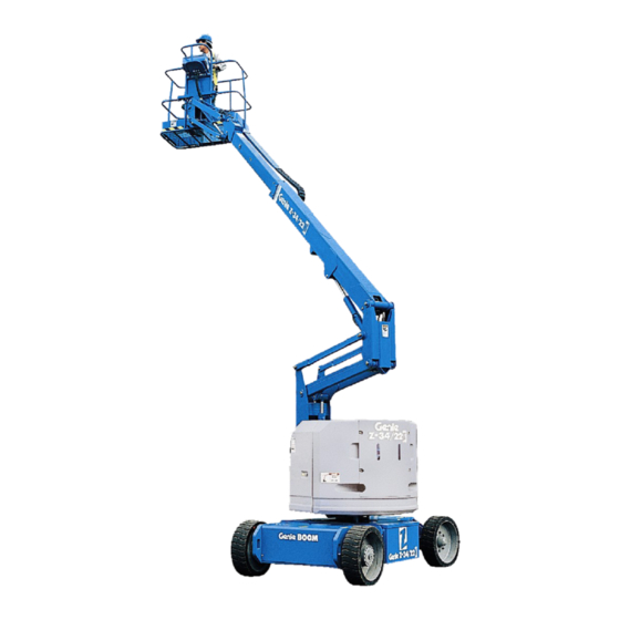
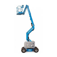
Genie Z-34/22N Manuals
Manuals and User Guides for Genie Z-34/22N. We have
5
Genie Z-34/22N manuals available for free PDF download: Service Manual, Service And Repair Manual, Operator's Manual
Genie Z-34/22N Service Manual (188 pages)
Brand:
Genie
| Category:
Boom Lifts
| Size: 10.95 MB
Table of Contents
April
2
Find a Manual for this Model
2
Serial Number Legend
5
Safety Rules
6
Table of Contents
8
Specifications
14
Machine Specifications
14
Machine Component Weights
15
Performance Specifications
16
Hydraulic Specification
17
Viscosity Index
17
Kinematic Viscosity
18
Fluid Properties
19
ISO Grade Viscosity Index
19
Cst @ 200°F / 100°C
19
Cst @ 104°F / 40°C
19
Hydraulic Component Specifications
20
Manifold Component Specifications
20
Machine Torque Specifications
21
Hydraulic Hose and Fitting Torque Specifications
22
Torque Procedure
23
SAE and Metric Fasteners Torque Charts
25
Scheduled Maintenance Procedures
26
Introduction
26
Pre-Delivery Preparation Report
29
Maintenance Inspection Report
31
Checklist a Procedures
32
Inspect the Manuals and Decals
32
Perform Pre-Operation Inspection
33
Perform Function Tests
33
Perform 30 Day Service
34
Grease the Turntable Rotation Bearing and Worm Drive Gear
34
Replace the Drive Hub Oil
35
Checklist B Procedures
36
Inspect the Battery
36
Inspect the Electrical Wiring
37
Inspect the Tires, Wheels and Lug Nut Torque
38
Confirm the Proper Brake Configuration
39
Check the Drive Hub Oil Level and Fastener Torque
39
Test the Ground Control Override
40
Test the Platform Self-Leveling
40
Test the Drive Brakes
41
Test the Drive Speed - Stowed Position
41
Test the Drive Speed - Raised or Extended Position
42
Test the Alarm Package (if Equipped)
43
Test the Turntable Rotation Stop
44
Check the Electrical Contactors
44
Perform Hydraulic Oil Analysis
45
Test the Emergency Power System
45
Checklist C Procedures
47
Grease the Platform Overload Mechanism (if Equipped)
47
Test the Platform Overload System (if Equipped)
47
Checklist D Procedures
49
Check the Boom Wear Pads
49
Check the Free-Wheel Configuration
50
Check the Turntable Rotation Bearing Bolts
51
Replace the Drive Hub Oil
52
Replace the Hydraulic Tank Return Filter Element
52
Inspect for Turntable Bearing Wear
53
Checklist E Procedures
54
Test or Replace the Hydraulic Oil
54
Grease the Steer Axle Wheel Bearings
56
April
57
Repair Procedures
58
Introduction
58
Platform Controls
60
Controllers
60
Platform Components
62
Platform Leveling Slave Cylinder
62
Platform Rotator
63
Platform Overload System
64
Jib Boom Components
67
Platform Overload System
67
Jib Boom Bell Crank (Models Without Rotating Jib Boom)
68
Jib Boom Bell Crank (Models with Rotating Jib Boom)
69
Jib Boom Lift Cylinder
71
Primary Boom Components
72
Cable Track
72
How to Repair the Primary Boom Cable Track
72
Primary Boom
73
How to Remove the Primary Boom
73
How to Disassemble the Primary Boom
75
Primary Boom Lift Cylinder
76
Primary Boom Extension Cylinder
78
Platform Leveling Master Cylinder
80
Secondary Boom Components
81
Secondary Boom
82
Secondary Boom Lift Cylinder
87
Hydraulic Pump
90
Auxiliary and Function Pump
90
Manifolds
91
7-1 Function Manifold Components
91
Valve Adjustments - Function Manifold
95
How to Adjust the System Relief Valve
95
How to Adjust the Primary Boom down Relief Valve
95
How to Adjust the Secondary Boom down Relief Valve
96
How to Adjust the Primary Boom Extend Relief Valve
96
How to Adjust the Turntable Rotate Relief Valve
97
Jib Boom and Platform / Jib Boom Rotate Manifold Components
98
Valve Coils
100
How to Test a Coil Diode
101
Turntable Rotation Components
103
Turntable Rotation Hydraulic Motor
103
Steer Axle Components
104
Hub and Bearings
104
How to Remove the Hub and Bearings
104
How to Install the Hub and Bearings
104
Non-Steer Axle Components
106
Motor Controller
106
Fault Codes
107
Introduction
107
Fault Code Charts
109
Schematics
112
Introduction
112
Section 6 Schematics
112
Electrical Symbol Legend
113
Hydraulic Symbols Legend
114
Limit Switch Location Legend
115
Electrical Schematics - Options
116
April
116
Power Cable Wiring Diagram
117
Drive Contactor Panel Wiring Diagram
118
Manifold and Limit Switch Wiring Diagram
121
LVI/BCI Option Wiring Diagram
122
Work and Drive Lights Option
125
CTE Option, (CE Models)
126
Charger Interlock Option
129
Hydraulic Schematics
130
Hydraulic Schematic
131
Electrical Schematics - ANSI / CSA / as Models
132
Electrical Schematic, (ANSI / CSA / AS) (before Serial Numbers Z30N10-12119, Z34N10-8857 and Z3410-7774)
133
Ground Control Box Terminal Strip Wiring Diagram, (ANSI / CSA / AS) (before Serial Numbers Z3010-12119, Z34N10-8857 and Z3410-7774)
136
Ground Control Box Terminal Strip Wiring Diagram, (ANSI / CSA / AS) (before Serial Numbers Z3010-12119, Z34N10-8857 and Z3410-7774)
137
Ground Control Box Switch Panel Wiring Diagram, (ANSI / CSA / AS), (before Serial Numbers Z30N10-12119, Z34N10-8857 and Z3410-7774)
138
Platform Control Box Wiring Diagram, (ANSI / CSA / AS) (before Serial Numbers Z30N10-12119, Z34N10-8857 and Z3410-7774)
141
Electrical Schematics - CE Models
142
Electrical Schematic, (CE), (before Serial Numbers Z30N10-12119, Z34N10-8857 and Z3410-7774)
143
Ground Control Box Terminal Strip Wiring Diagram, (CE) (before Serial Numbers Z30N10-12119, Z34N10-8857 and Z3410-7774)
147
Ground Control Box Switch Panel Wiring Diagram, (CE) (before Serial Numbers Z30N10-12119, Z34N10-8857 and Z3410-7774)
148
Platform Control Box Wiring Diagram, (CE) (before Serial Numbers Z30N10-12119, Z34N10-8857 and Z3410-7774)
151
Electrical Schematics - ANSI and CSA Models
152
Electrical Schematic, (ANSI / CSA), (from Serial Numbers Z30N10-12119, Z34N10-8857 and Z3410-7774 to Z30N13-14695, Z34N13-10622 and Z3413-9441 )
153
Electrical Schematic, (ANSI / CSA)
157
Z3413-9442 to Z30N14-15221, Z34N14-10983 and Z3414-9685)
157
Ground Control Box Terminal Strip Wiring Diagram, (ANSI / CSA) (from Serial Numbers Z30N10-12119, Z34N10-8857 and Z3410-7774 to Z30N13-14695, Z34N13-10622 and Z3413-9441)
161
Ground Control Box Switch Panel Wiring Diagram, (ANSI / CSA), (from Serial Numbers Z30N10-12119, Z34N10-8857 and Z3410-7774)
162
Platform Control Box Wiring Diagram, (ANSI / CSA), (from Serial Numbers Z30N10-12119, Z34N10-8857 and Z3410-7774)
167
Z3413-9442 to Z30N14-15221, Z34N14-10983 and Z3414-9685)
168
Electrical Schematics - as / CE Models
170
Electrical Schematic, (as / CE), (from Serial Numbers Z30N10-12119, Z34N10-8857 and Z3410-7774 to Z30N13-14695, Z34N13-10622 and Z3413-9441)
171
Electrical Schematic, (as / CE)
175
Z3413-9442 to Z30N14-15221, Z34N14-10983 and Z3414-9685)
175
Ground Control Box Terminal Strip Wiring Diagram, (as / CE) (from Serial Numbers Z30N10-12119, Z34N10-8857 and Z3410-7774 to Z30N13-14695, Z34N13-10622 and Z3413-9441)
179
Ground Control Box Switch Panel Wiring Diagram, (as / CE) (from Serial Numbers Z30N10-12119, Z34N10-8857 and Z3410-7774 to Z30N13-14695, Z34N13-10622 and Z3413-9441)
181
Ground Control Box Terminal Strip Wiring Diagram, (as / CE) (from Serial Numbers Z30N13-14696, Z34N13-10623 and Z3413-9442 to Z30N14-15221, Z34N14-10983 and Z3414-9685)
183
Platform Control Box Wiring Diagram, (as / CE) (from Serial Numbers Z30N10-12119, Z34N10-8857 and Z3410-7774 to Z30N13-14695, Z34N13-10622 and Z3413-9441)
185
Platform Control Box Wiring Diagram, (as / CE)
186
Z34N14-10983 and Z3414-9685
186
Advertisement
Genie Z-34/22N Service And Repair Manual (131 pages)
Lift Capacity 500 lbs
Brand:
Genie
| Category:
Lifting Systems
| Size: 7.46 MB
Table of Contents
Introduction
2
Find a Manual for this Model
2
September
2
Revision History
3
Serial Number Legend
4
Safety Rules
5
Table of Contents
7
Specifications
11
Machine Specifications
11
Performance Specifications
12
Hydraulic Specification
13
Hydraulic Component Specifications
15
Manifold Component Specifications
15
Machine Torque Specifications
16
Hydraulic Hose and Fitting Torque Specifications
17
Torque Procedure
18
SAE and Metric Fasteners Torque Charts
20
Repair Procedures
21
Platform Controls
23
Controllers
23
Platform Components
25
Platform Leveling Slave Cylinder
25
Platform Rotator
26
Platform Overload System
27
Jib Boom Components
30
Jib Boom Bell Crank (Models Without Rotating Jib Boom)
31
Jib Boom Bell Crank (Models with Rotating Jib Boom)
31
Jib Boom Bell Crank (Models with Rotating Jib Boom)
32
Jib Boom Lift Cylinder
34
Primary Boom Components
35
Cable Track
35
How to Repair the Primary Boom Cable Track
35
Primary Boom
35
September
35
How to Remove the Primary Boom
36
How to Disassemble the Primary Boom
38
Primary Boom Lift Cylinder
39
Primary Boom Extension Cylinder
41
Platform Leveling Master Cylinder
43
Secondary Boom Components
44
Secondary Boom
45
Secondary Boom Lift Cylinders
50
Hydraulic Pump
53
Auxiliary and Function Pump
53
Manifolds
54
7-1 Function Manifold Components
54
Valve Adjustments - Function Manifold
58
How to Adjust the System Relief Valve
58
How to Adjust the Primary Boom down Relief Valve
58
How to Adjust the Secondary Boom down Relief Valve
59
How to Adjust the Primary Boom Extend Relief Valve
59
How to Adjust the Turntable Rotate Relief Valve
60
Jib Boom and Platform / Jib Boom Rotate Manifold Components
61
Valve Coils
63
How to Test a Coil Diode
64
Turntable Rotation Components
65
Turntable Rotation Hydraulic Motor
65
Steer Axle Components
66
Hub and Bearings
66
How to Remove the Hub and Bearings
66
How to Install the Hub and Bearings
66
Non-Steer Axle Components
67
Motor Controller
67
Fault Codes
68
September
68
Fault Code Charts
70
Schematics
73
Section 5 Schematics
73
Electrical Symbol Legend
74
Hydraulic Symbols Legend
75
Limit Switch Location Legend
76
Electrical Schematics - Options
77
Power Cable Wiring Diagram
77
Electrical Schematics – Options
77
Drive Contactor Panel Wiring Diagram
79
Manifold and Limit Switch Wiring Diagram
81
LVI/BCI Option Wiring Diagram
83
Charger Interlock Option
85
CTE Option, (CE Models)
87
Hydraulic Schematics
89
Hydraulic Schematic
89
Electrical Schematics - ANSI / CSA / as Models
91
Electrical Schematic, (ANSI / CSA / AS) (before Serial Numbers Z30N10-12119, Z34N10-8857 and Z3410-7774)
91
Electrical Schematics – ANSI / CSA / as Models
91
Ground Control Box Terminal Strip Wiring Diagram, (ANSI / CSA / as before Serial Numbers Z3010-12119, Z34N10-8857 and Z3410-7774)
93
Ground Control Box Terminal Strip Wiring Diagram, (ANSI / CSA / AS) (before Serial Numbers Z3010-12119, Z34N10-8857 and Z3410-7774)
95
Ground Control Box Terminal Strip Wiring Diagram, (ANSI / CSA / AS) (before Serial Numbers Z3010-12119, Z34N10-8857 and Z3410-7774)
96
Ground Control Box Switch Panel Wiring Diagram, (ANSI / CSA / as before Serial Numbers Z30N10-12119, Z34N10-8857 and Z3410-7774)
97
Ground Control Box Switch Panel Wiring Diagram, (ANSI / CSA / AS) (before Serial Numbers Z30N10-12119, Z34N10-8857 and Z3410-7774)
98
Platform Control Box Wiring Diagram, (ANSI / CSA / AS) (before Serial Numbers Z30N10-12119, Z34N10-8857 and Z3410-7774)
99
Platform Control Box Wiring Diagram, (ANSI / CSA / as before Serial Numbers Z30N10-12119, Z34N10-8857 and Z3410-7774)
100
Electrical Schematics - CE Models
101
Electrical Schematic, (CE), (before Serial Numbers Z30N10-12119, Z34N10-8857 and Z3410-7774)
101
September
101
Ground Control Box Terminal Strip Wiring Diagram, (CE), (before Serial Numbers Z30N10-12119, Z34N10-8857 and Z3410-7774)
105
Ground Control Box Switch Panel Wiring Diagram, (CE) (before Serial Numbers Z30N10-12119, Z34N10-8857 and Z3410-7774)
107
Platform Control Box Wiring Diagram, (CE) (before Serial Numbers Z30N10-12119, Z34N10-8857 and Z3410-7774)
109
Electrical Schematics - ANSI and CSA Models
111
Electrical Schematic, (ANSI / CSA), (from Serial Numbers Z30N10-12119, Z34N10-8857 and Z3410-7774)
111
Electrical Schematics – ANSI and CSA Models
111
Ground Control Box Terminal Strip Wiring Diagram, (ANSI / CSA), (from Serial Numbers Z30N10-12119, Z34N10-8857 and Z3410-7774)
115
Ground Control Box Switch Panel Wiring Diagram, (ANSI / CSA from Serial Numbers Z30N10-12119, Z34N10-8857 and Z3410-7774)
117
Ground Control Box Switch Panel Wiring Diagram, (ANSI / CSA), (from Serial Numbers Z30N10-12119, Z34N10-8857 and Z3410-7774)
118
Platform Control Box Wiring Diagram, (ANSI / CSA), (from Serial Numbers Z30N10-12119, Z34N10-8857 and Z3410-7774)
119
Electrical Schematics - as / CE Models
121
Electrical Schematic, (as / CE), (from Serial Numbers Z30N10-12119, Z34N10-8857 and Z3410-7774)
121
Electrical Schematics – as / CE Models
121
Ground Control Box Terminal Strip Wiring Diagram, (as / CE), (from Serial Numbers Z30N10-12119, Z34N10-8857 and Z3410-7774)
125
Ground Control Box Switch Panel Wiring Diagram, (as / CE) (from Serial Numbers Z30N10-12119, Z34N10-8857 and Z3410-7774)
127
Platform Control Box Wiring Diagram, (as / CE), (from Serial Numbers Z30N10-12119, Z34N10-8857 and Z3410-7774)
129
Genie Z-34/22N Operator's Manual (43 pages)
Boom Lifts
Brand:
Genie
| Category:
Lifting Systems
| Size: 0.48 MB
Table of Contents
Table of Contents
2
Safety Rules
3
Electrocution Hazards
4
Tip-Over Hazards
4
Z-34/22N, Maximum Slope Rating, Stowed Position
6
Z-34/22 DC, Maximum Slope Rating, Stowed Position
6
Fall Hazards
8
Collision Hazards
8
Component Damage Hazard
9
Damaged Machine Hazards
9
Decal Legend
10
Bodily Injury Hazard
10
Battery Safety
11
Burn Hazards
11
Component Damage Hazards
11
Tip-Over Hazard
11
Platform Control Panel
12
Controls
12
Ground Control Panel
13
Legend
14
Fundamentals
15
Pre-Operation Inspection
15
Check the Hydraulic Oil Level
17
Observe and Obey
17
Maintenance Symbols Legend
17
Maintenance
17
Check the Batteries
18
Check the Tire Pressure
18
Standard Batteries
18
Scheduled Maintenance
19
Test Emergency Stop
20
At the Ground Controls
20
Function Tests
20
At the Platform Controls
21
Test the Boom Functions
21
Test the Tilt Sensor
21
Test the Horn
22
Test Machine Functions
22
Test the Foot Switch
22
Test the Steering
22
Test Drive and Braking
23
Test Limited Drive Speed
23
Test the Lift/Drive Select Function
24
Test the Drive Enable System
24
Workplace Inspection
25
Operating Instructions
26
Emergency Stop
27
Operation from Ground
27
Auxiliary Controls
27
Operation from Platform
27
Driving on a Slope
28
To Steer
28
To Drive
28
Low Voltage Interrupt
29
To Determine the Slope Grade
29
Drive Enable
29
Machine Not Level Indicator Light
30
Platform Overload Indicator Light
30
Aircraft Protection Package
30
ANSI, CSA and aus Models
30
Fall Protection
31
After each Use
31
Battery and Charger Instructions
32
Dry Battery Filling and Charging
32
To Charge the Batteries
32
Maintenance-Free Batteries
32
Free-Wheel Configuration for Winching
33
Transport and Lifting Instructions
33
Securing the Chassis
34
Securing the Platform
34
Securing to Truck or Trailer for Transit
34
Lifting Instructions
35
Inspection for Decals with Words
36
Decals
36
Inspection for Decals with Symbols
38
Drive Speeds, Maximum
40
Maximum Slope Rating, Stowed Position
40
Floor Loading Information
40
Specifications
40
Range of Motion
42
Advertisement
Genie Z-34/22N Operator's Manual (36 pages)
Brand:
Genie
| Category:
Boom Lifts
| Size: 0.92 MB
Table of Contents
Table of Contents
2
Safety
9
Controls
10
Pre-Operation Inspection
12
Maintenance
14
Scheduled Maintenance
15
Function Tests
16
Workplace Inspection
21
Operating Instructions
22
Transport & Lifting Instructions
29
Specifications
32
Decals
32
Power Unit
33
Specifications
34
Genie Z-34/22N Operator's Manual (31 pages)
Brand:
Genie
| Category:
Lifting Systems
| Size: 1.93 MB
Table of Contents
Table of Contents
2
Safety Rules
3
Controls
10
Pre-Operation Inspection
12
Function Tests
14
Work Place Inspection
18
Operating Instructions
19
Transport Instructions
24
Decals
26
Specifications
29
Advertisement
Related Products
Genie Z-34/22
Genie Z-34 Bi-Energy
Genie Z-34/22 N
Genie Z-34/22 IC
Genie Z-34/22 BE
Genie Z-34/22DC
Genie Z-34/22 DC
Genie Z-34/22IC
Genie Z-30/20N RJ' Z-34/22N
Genie Z-30/20HD
Genie Categories
Garage Door Opener
Lifting Systems
Boom Lifts
Security Camera
Digital Camera
More Genie Manuals
Login
Sign In
OR
Sign in with Facebook
Sign in with Google
Upload manual
Upload from disk
Upload from URL