Sign In
Upload
Manuals
Brands
Comtech EF Data Manuals
Modem
CDM-700
Comtech EF Data CDM-700 Manuals
Manuals and User Guides for Comtech EF Data CDM-700. We have
1
Comtech EF Data CDM-700 manual available for free PDF download: Installation And Operation Manual
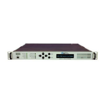
Comtech EF Data CDM-700 Installation And Operation Manual (256 pages)
High Speed Satellite Modem
Brand:
Comtech EF Data
| Category:
Modem
| Size: 7.45 MB
Table of Contents
Preface
17
Installation and Operation Manual
1
Table of Contents
5
Customer Support
17
About this Manual
18
Reporting Comments or Suggestions Concerning this Manual
18
Conventions and References
18
Metric Conversion
18
Cautions and Warnings
18
Recommended Standard Designations
18
Electrical Safety
19
Fuses
19
Environmental
19
Installation
19
Telecommunications Terminal Equipment Directive
20
CE Mark
20
Rohs Compliancy
20
EMC (Electromagnetic Compatibility)
20
Warranty Policy
22
Limitations of Warranty
22
Exclusive Remedies
23
Chapter 1. INTRODUCTION
25
Overview
25
Figure 1-1. CDM-700 High Speed Satellite Modem
25
Standard Features
26
Software - Flash Upgrading
26
Turbo Product Coding (TPC)
27
Appendix F.E /N Measurement
27
Table 1-1. Major Assemblies
27
Major Assemblies
27
Allowable Data Interface Combinations
27
FAST and Hardware Options
29
Table 1-2. FAST and Hardware Options
29
New in this Release
30
Chapter 2. INSTALLATION
31
Unpacking and Inspection
31
Mounting
32
Method A: Optional Rear-Mounting Support Brackets
32
Figure 2-1. Installation of Optional Rear-Mounting Support Brackets (Kit KT/6228-2)
33
Method B: Optional Installation of Side-Railings
34
Figure 2-2. Installation of Optional Side-Railings (FP/SL0006)
34
Chapter 3. FUNCTIONAL DESCRIPTION
35
Description
35
Interfaces Modules
37
Figure 3-1. CDM-700 Modem Block Diagram
37
Data Interfaces and Data Transfer Across the Link
38
Simplex and Asymmetric Operation
38
Allowable Data Interfaces in Slot 1 and Slot 2
39
Figure 3-2. Rear Panel View
39
Chapter 4. PHYSICAL DESCRIPTION
41
Introduction
41
Figure 4-1. CDM-700 Satellite Modem
41
Front Panel
42
Rear Panel
43
External Cables
43
IEC Line Input Connector
43
Figure 4-2. CDM-700 Rear Panel
43
Rx and Tx if Connectors (J1 and J3)
44
10/100 Ethernet Remote Port Connector (J4)
44
Serdes (Private Communications Link) (J6)
44
External Reference Connector (J7)
44
Alarm Form C Connector (P1)
44
Remote Control Connector (RS-232/RS-485), P2
44
Data Interface Connector
44
Dimensional Envelope
45
Figure 4-3. CDM-700 Dimensional Envelope (70/140 Mhz)
45
Chapter 5. CONNECTOR PINOUTS
47
External Connections
47
Figure 5-1. CDM-700 Chassis - Rear Panel
47
10/100 Ethernet Management Port Connector Pinout - J4
49
Tx / Rx Connector Pinout – J1 / J
49
Serdes Port Connector - J6 (Earlier Chassis Only)
49
ASYNC Connector Pinout - J6 (Rev. a and Later Chassis)
50
External Reference Input (Main Chassis) - J7
50
Alarm Connector Pinout - P1
51
RS-232/485 Remote Port Connector Pinout - P2
53
Data Interfaces
53
Chapter 6. FRONT PANEL OPERATION
55
Introduction
55
Figure 6-1. Front Panel View
55
Front Panel LED Indicators
56
Table 6-1. Front Panel LED Indicators
56
Front Panel Keypad
57
Figure 6-2. Keypad
57
Front Panel Vacuum Flourescent Display (VFD)
58
Menu Matrix
59
Opening Screen
60
SELECT: (Main) Menu
60
Select:) Config
61
CONFIG:) Remote
62
Remote Control: Local
62
Remote Control: Serial
62
Remote Control: Ethernet
63
Snmp Community
64
CONFIG:) Tx
66
Tx: Mod
66
Tx: Code
67
Tx: Freq
68
Tx: Data
68
Tx: Sym
69
Tx: Pwr
69
Tx: Scram
70
CONFIG:) Rx
71
Rx: dem (Demod)
71
Rx: Code
73
Rx: Freq
73
Rx: Data
73
Rx: Sym
74
Rx: Descrm
74
Rx: Eb/No
74
CONFIG): Intfc1
76
Intfc1 (CDI-10 Dual G.703 Interface)
77
Intfc1: Alarm
77
Intfc1: Port1
77
Intfc1: Port2
84
Intfc1: Ext-Clk
84
CONFIG:) Intfc2 (CDI-10 Dual G.703 Interface)
84
CONFIG:) Intfc1 (CDI-50 OC-3 Interface)
85
Intfc1 OC-3: Tx
85
Intfc1 OC-3: Rx
86
CONFIG:) Intfc1 (CDI-60 HSSI Interface)
88
Intfc1 HSSI: Tx
88
Intfc1 HSSI: Rx
89
Intfc1 HSSI: CTS/RTS
91
Intfc1 HSSI: Alarm
92
CONFIG:) Intfc2 (CDI-60 HSSI Interface)
92
CONFIG:) Intfc1 (CDI-70 Gigabit Ethernet Interface)
92
Intfc1 Gigabit Ethernet: Tx
93
Intfc1 Gigabit Ethernet: Rx
94
Intfc1 Gigabit Ethernet: man
95
Intfc1 Gigabit Ethernet: Stats
95
Intfc1 Gigabit Ethernet: Negotiation
103
Manual Negotiation
103
Master/Slave Options
103
Speed Options
104
Duplex Options
104
Automatic Negotiation
104
View Negotiation
105
CONFIG:) Intfc2 (CDI-70 Gigabit Ethernet Interface)
105
CONFIG:) Ref
105
CONFIG:) Aux
105
SELECT:) Monitor
106
Monitor: Alarms
106
Monitor: Rx-Params
110
Monitor: Event-Log
111
SELECT:) Test
112
Figure 6-3. Traffic Flow Loopback Block Diagrams
113
SELECT:) Info
115
INFO: Rem
115
INFO: Tx
115
INFO: Rx
116
Info: 1:1
116
INFO: Intfc1 / Intfc2
117
SELECT:) Save/Load
118
Save/Load Configuration: Save
118
Save/Load Configuration: Load
119
SELECT:) Util
120
UTIL: Rt-Clk
120
UTIL: Ref
120
Util: ID
120
UTIL: Display
121
UTIL: Firmware
121
Util: Fast
123
Chapter 7 .Forward Error Correction Options
127
Introduction
127
Turbo Product Codec
127
Range of Data Rates
128
Eb/No, Spectral Efficiency and Occupied Bandwidth
128
End-To-End Processing Delay (Latency)
129
Table 7-1. Eb/No, Spectral Efficiency and Occupied Bandwidth
129
Figure 7-1. CDM-700 Gigabit Ethernet Latency with Modem in if Loopback
130
Figure 7-2. CDM-700 HSSI Latency with Modem in if Loopback
130
Figure 7-3. Rate 3/4 TPC QPSK, 8-PSK, 16-QAM, 64-QAM
131
Figure 7-4. Rate 7/8 TPC QPSK, 8-PSK, 16-QAM, 64-QAM
132
Chapter 8. CLOCK MODES
133
Introduction
133
Figure 8-1. Typical Data Interface (Features Vary by Interface)
134
Dual G.703 Interface
135
Dual G.703 Interface Transmit Clocking
135
Dual G.703 Interface Receive Clocking
135
Figure 8-2. CDI-10 G.703 Dual G.703 Interface
135
OC-3 / STM-1 (Optical / Coaxial) 155.52 Mbps Interface
136
OC-3 / STM-1 Interface Transmit Clocking
136
OC-3 / STM-1 Interface Receive Clocking
136
Figure 8-3. CDI-50 OC-3 / STM-1 Interface
136
HSSI Interface
137
HSSI Interface Transmit Clocking
137
HSSI Interface Receive Clocking
137
Figure 8-4. CDI-60 HSSI Data Interface
137
10/100/1000 Gigabit Ethernet Interface
138
Chapter 9. FLASH UPGRADING
139
Introduction
139
Figure 9-1. Flash Update Via Internet
139
Base Modem FTP Upload Procedure
140
Chapter 10. Summary of Specifications
143
Summary of Specifications
143
Table 10-1. Summary of Specifications
144
Table 10-2. Definition of Points for Spectral Mask
144
Figure 10-1. Spectral Mask
144
Data Rate Range
145
70/ 140 Mhz Modulator
146
L-Band Modulator
146
140 Mhz Demodulator
147
L-Band Demodulator
147
Figure 10-2. 70/140 Mhz and L-Band Carrier Input Level Versus Symbol Rate
148
BER Performance
149
Adjacent Channel
149
Data Interface (Optional)
150
Environmental and Physical
150
Introduction
151
Chapter 11. REMOTE CONTROL
151
Basic Protocol
152
Packet Structure
153
Start of Packet
153
Address
153
Instruction Code
154
Instruction Code Qualifier
154
Message Arguments
155
End of Packet
155
Remote Commands and Queries
156
Chapter 12. SNMP INTERFACE
183
SNMP Interface
183
Management Information Base (MIB) Files
184
SNMP Community Strings
185
Common Private MIB
185
CDM-700 Common Private Mib
185
System Information Group
185
Remote Ethernet Group
185
Ethernet SNMP Group
185
Interface FAST OPTIONS Group
185
Modem Reference Group
186
Monitor Group
186
Test Group
186
Save/Load Group
186
Firmware Group
186
System Log Group
186
Modulator Group
186
Demodulator Modulator Group
186
Interface Group
186
E3T3STS1 Group
187
OC3 Group
187
HSSI Group
187
Gigabit Ethernet Group
187
CDM Redundancy Objects
187
SNMP Traps
187
CDM Monitor Objects
187
Mib-II
188
Chapter 13. TELNET INTERFACE
189
Telnet Interface
189
Caution Using Windows Telnet Client
191
Using Telnet
192
Telnet Example
192
Chapter 14 .Ethernet Network Configurations
193
Introduction
193
Ethernet Routers and Switches
193
Ethernet Configuration Examples
194
Ethernet Network Overview
194
Figure 14-1. Networking Loop with Switches
194
Ethernet Redundancy with CRS-300
195
Wired-Thru Connection
195
Wired-Around Connection
195
Hub-To-Hub with Standard Traffic Using Switches
196
Figure 14-2. Networking Loop Example
196
Figure 14-3. Networking Loop Example (Simplified)
196
Hub-To-Hub with Standard Traffic Using Routers
198
Figure 14-4. Hub-To-Hub with Standard Traffic Using Routers
198
Figure 14-5. Wired-Thru for Hub-To-Hub with Standard Traffic Using Routers
199
Figure 14-6. Wired-Around for Hub-To-Hub with Standard Traffic Using Routers
199
Hub-To-Remotes with Standard Traffic Using Routers or Switches
200
Figure 14-7. Hub-To-Remotes with Standard Traffic Using Routers or Switches
200
Figure 14-8. Wired-Thru for Hub-To-Remotes with Standard Traffic Using Routers or Switches
201
Figure 14-9. Wired-Around for Hub-To-Remotes with Standard Traffic Using Routers or Switches
201
Hub-To-Remotes, Split-Path Traffic Using Routers (Point-To-Multipoint)
202
Figure 14-10. Point-To-Multipoint Using Routers
202
Figure 14-11. Wired-Thru for Point-To-Multipoint with Routers
203
Figure 14-12. Wired-Around for Point-To-Multipoint with Routers
203
Hub-To-Remotes, Split-Path Traffic Using Switches (Point-To-Multipoint)
204
Figure 14-13. Point-To-Multipoint Using Switches
204
Figure 14-14. Wired-Thru, Hub-To-Remotes, Split-Path Traffic Using Switches (Point-To-Multipoint)
205
Figure 14-15. Wired-Around, Hub-To-Remotes, Split-Path Traffic Using Switches (Point-To-Multipoint)
205
Chapter 15. WEB SERVER
207
Overview
207
Web Server Usage
207
Web Server Menu Tree
208
Table 15-1 Web Server Menu Tree
208
Home
209
Home Page
209
Figure 15-1. CDM-700 Home Page
209
Home: Contact Page
210
Figure 15-2. Home: Contact Information Page
210
Home: Support Page
211
Figure 15-3. Home: Customer Support Page
211
Admin
212
Admin: Access Page
212
Admin Pages
212
Figure 15-4. Admin: Access Page
212
Admin: Remote Page
213
Figure 15-5. Admin: Remote Page
213
Config MDM (Modem Configuration)
214
Config MDM: Modem Page
214
Figure 15-6. Config MDM: Modem Page
214
Config MDM: Modem Utilities Page
215
Figure 15-7. Config MDM: Modem Utilities Page
215
Config MDM: INTF1 (Interface 1) Page
216
Figure 15-8. Config MDM: INTF1 Page (Default - no Module Installed)
216
Config MDM: INTF1 - E3/T3/STS1 Page
217
Figure 15-9. Config MDM: INTF1 - E3/T3/STS1 (Dual G.703) Page
217
Config MDM: INTF1 - OC3 (Optical) Page
218
Figure 15-10. Config MDM: INTF1 - OC3 Page
218
Config MDM: INTF1 - HSSI Page
219
Figure 15-11. Config MDM: INTF1 - HSSI Page
219
Config MDM: INTF2 (Interface 2) Page
220
Figure 15-12. Config MDM: INTF2 Page (Default - no Module Installed)
220
Config MDM: INTF2 - GBEI (Gigabit Ethernet) Main Page
221
Figure 15-13. Config MDM: INTF2 - GBEI Main Page
221
GBEI: Statistics Page
222
GBEI: VLAN Feature Page
223
Figure 15-16. Statistics: (Main) Modem Status Page
224
Stats (Statistics)
224
Stats: Modem Status Page
224
Figure 15-17. Statistics: Modem Logs Page
225
Stats: Modem Logs Page
225
Figure 15-18. Maintenance: (Main) Unit Information Page
226
Maint (Maintenance) Page: Unit Information
226
Appendix A. FAST ACTIVATION PROCEDURE
227
Introduction
227
Activation Procedure
228
Serial Number
228
View Currently Installed Features
228
Enter Access Codes
228
Appendix B.Dual E3 / T3 / Sts-1 Interface (CDI-10)
229
Introduction
229
Figure B-1. Block Diagram of Dual E3/T3/STS-1 Data Interface Module
230
Figure B-2. Dual E3/T3/STS-1 Data Interface Module (CDI-10)
230
Summary of Specifications
231
Connector Pinouts
232
Appendix C.Oc-3 / Stm-1 Interface (CDI-50)
233
Introduction
233
Figure C-1. Optical / Coaxial Interface Block Diagram
234
Figure C-2. CDI-50 Rear Panel
234
General Specifications
235
Connector Pinout
236
Appendix D. HSSI INTERFACE (CDI-60)
237
Introduction
237
Figure D-1. HSSI Interface Block Diagram
238
Figure D-2. HSSI Interface
238
Physical Description
239
Figure D-3. Continuous and Gap Clock at TT
240
General Specifications
240
Environmental and Physical
241
Connector Pinout
242
Table D-2. Connector Pinout
242
Appendix E. 10/100/1000 BASE-TINTERFACE (GBEI) (CDI-70)
243
Figure E-1. CDI-70 1000 Base-T Gigabit Ethernet Interface (GBEI)
243
Introduction
243
Physical Description
244
Table E-1. Interface Specifications
244
General Specifications
244
Connector Pinout
245
Figure E-2. GBEI Interface Option Board – Phase 1
245
Table E-2. Connector Pinout
245
GBEI Software Upload Procedure
246
Upgrading the Gigabit Ethernet Interface Card Firmware
247
Download the Files
247
Connect the PC to the Interface
247
Reflash the Unit
247
Revision
247
GBEI Operational Setups
249
Appendix F. E B /NMEASUREMENT
251
Metric Conversions
255
Advertisement
Advertisement
Related Products
Comtech EF Data CDM-710
Comtech EF Data CDM-710L
Comtech EF Data CDM-710G
Comtech EF Data CDM-740
Comtech EF Data CDM-760
Comtech EF Data CDM-750
Comtech EF Data CDM-Qx
Comtech EF Data CDM-625
Comtech EF Data CDM-500
Comtech EF Data Vipersat CDM-570L
Comtech EF Data Categories
Modem
Amplifier
Switch
Network Router
Media Converter
More Comtech EF Data Manuals
Login
Sign In
OR
Sign in with Facebook
Sign in with Google
Upload manual
Upload from disk
Upload from URL