Sign In
Upload
Manuals
Brands
Comtech EF Data Manuals
Modem
CDM-760
Comtech EF Data CDM-760 Manuals
Manuals and User Guides for Comtech EF Data CDM-760. We have
1
Comtech EF Data CDM-760 manual available for free PDF download: Installation And Operation Manual
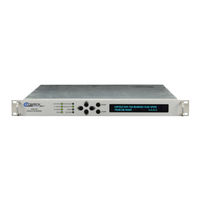
Comtech EF Data CDM-760 Installation And Operation Manual (441 pages)
Advanced High-Speed Trunking Modem
Brand:
Comtech EF Data
| Category:
Modem
| Size: 9.41 MB
Table of Contents
Table of Contents
8
F Igures
20
Tables
23
Preface
26
About this Manual
26
Conventions and References
26
Patents and Trademarks
26
Warnings, Cautions and Notes
26
Recommended Standard Designations
27
Safety and Compliance
27
Electrical Safety and Compliance
27
Electrical Installation
27
Operating Environment
28
European Union Radio Equipment and Telecommunications Terminal Equipment (R&TTE) Directive (1999/5/EC) and en 301 489-1
28
European Union Electromagnetic Compatibility (EMC) Directive (2004/108/EC)
28
European Union Low Voltage Directive (LVD) (2006/95/EC)
29
European Union Rohs Directive (2002/95/EC)
29
European Union Telecommunications Terminal Equipment Directive (91/263/EEC)
29
CE Mark
29
Product Support
30
Comtech EF Data Headquarters
30
Warranty Policy
31
Limitations of Warranty
31
Exclusive Remedies
31
Chapter 1. Introduction
32
Overview
32
Figure 1-1. CDM-760 Advanced High-Speed Trunking Modem
32
Features
34
Physical Description
34
Standard Assemblies
34
Optional Assemblies
34
Dimensional Envelope
35
Figure 1-2. CDM-760 Dimensional Envelope
35
Physical Features
36
Front Panel Features
36
Figure 1-3. CDM-760 Front Panel View
36
Rear Panel Features
37
Figure 1-4. CDM-760 Rear Panel View
37
Rear Panel Standard Features
37
Rear Panel Optional Features
38
Verification
38
On-Site Firmware Updates
39
On-Site Operational Upgrades
39
Table 1-1. FAST and FAST-Accessible Hardware Options
39
Monitor and Control Interfaces
40
Specifications
40
System Specifications
40
Environmental and Physical
41
Base Unit Connectors
41
Test Functions
41
Modulator (Dual IF)
41
Demodulator (Dual IF)
42
Figure 1-5. 70/140 Mhz Input Level Vs. Symbol Rate
43
Figure 1-6. L-Band Input Level Vs. Symbol Rate
43
Es/No Performance
44
Adaptive Coding and Modulation (ACM)
46
Doubletalk ® Carrier-In-Carrier ® (Cnc)
47
Regulatory Compliance
47
Chapter 2. Installation
48
Unpack and Inspect the Equipment
48
Figure 2-1. Unpack and Inspect the Shipment
48
Install the Unit into a Rack Enclosure
49
Figure 2-2. Install the Unit into a Rack Enclosure
50
Install the Optional Rear Support Brackets Kit
51
Figure 2-3. Install the Optional Rear Support Brackets Kit
51
Install the Optional Bearingless Rack Slide Set
53
Figure 2-4. Install the Optional Bearingless Rack Slide Set
53
Chapter 3. Rear Panel Connections
54
Cabling Connection Types
54
Coaxial Cable Connections
54
Figure 3-1. Coaxial Connector Examples
54
Type 'BNC
55
Type 'F
55
Type 'N
55
Type 'SMA' (Subminiature Version 'A')
55
Type 'TNC
55
Cable Connections
56
D-Subminiature Cable Connections
56
Figure 3-2. D-Subminiature Connector Examples
56
Table 3-1. CDM-760 Rear Panel Connectors
57
IF Connector Group
58
Rx Connectors
58
Tx Connectors
58
J10 | TX MON Connector, Type 'SMA
58
Utility Connector Group
59
J1 | ALARM Connector, DB-15M
59
J2 | REDUNDANCY Connector, DB-9F
60
J3 | REMOTE Connector, DB-9M
60
J4 | MGMT Connector, RJ-45F
61
J8 | EXT REF (External Reference) Connector, BNC
61
Terrestrial Data Connector Group
62
J5 | DATA, J6 | DATA Connections, RJ-45F
62
J7 | OPTICAL Connection, 1000Base-SX Cage
63
Figure 3-4. Typical SFP Module Installation
63
Optional Optical Gigabit Ethernet Interface (P/N IC-0000058)
63
Optional PIIC Data Interface Slots
64
Figure 3-5. PIIC Data Interface Slots
64
Figure 3-6 Install a PIIC Data Module
64
Install an Optional PIIC Data Module
64
Optional High-Speed Packet Processor Connections
65
Cabling Connections
57
Figure 3-3. CDM-760 Cabling Connections
57
Figure 3-7. Optional High-Speed Packet Processor
57
Ground and Power Connections
66
Chassis Ground Interface
66
Figure 3-8. Chassis Ground Interface
66
230V Alternating Current (AC) Power Interface (Standard)
67
AC Operation - Apply Power
67
Figure 3-9. AC Power Interface
67
Figure 3-10. Apply AC Power to the Unit
67
AC Operation - Replace the Fuses
68
Figure 3-11. Replace the AC Fuses
68
Direct Current (DC) Power Interface (Optional)
69
DC Operation - Apply Power
69
DC Operation - Replace the Fuses
70
Chapter 4. Updating Firmware
72
Overview
72
Important Considerations before Proceeding
72
About Firmware File Acquisition and Modem Update
73
Get Started: Prepare for the Firmware Download
74
Required User-Supplied Items
74
To PC Connections
74
Configure the Terminal Emulator Program
74
Get the CDM-760 Management IP Address and Firmware Information
75
Make a Temporary Folder (Subdirectory) on the User PC
76
Use Windows Desktop to Make a Folder
76
Use the Run and Browse Windows to Make a Folder
77
Use Windows Explorer to Make a Folder
77
Use Windows Command-Line or Command Prompt to Make a Folder
78
Download and Extract the Firmware Update Files
78
Use Windows Desktop to View Folder Contents
80
Use Windows Command-Line to View Folder Contents
80
Upload the Firmware Files and Update the CDM-760 Unit
81
Important Considerations
81
Use Windows Command-Line to FTP Upload the Firmware Files (Ethernet-Based Firmware Update Procedure)
81
Use the HTTP Interface to Perform the Ethernet FTP Upload Procedure
83
Select the Updated Firmware for Modem Operation
84
Reboot the Modem
85
Chapter 5. Fast Activation Procedure
86
FAST Overview
86
About FAST Options
87
FAST Activation Procedure
87
FAST Activation Using the CDM-760 Front Panel
87
FAST Activation Using the CDM-760 HTTP (Web Server) Interface
88
Chapter 6. Front Panel Operation
90
Overview
90
LED Indicators
91
Table 6-1. LED Function
91
Keypad
92
Vacuum Fluorescent Display (VFD)
92
Opening Screen
93
Screen Saver
93
Cursor Behavior
93
Front Panel Menus
94
Table 6-2. CDM-760 Front Panel Menus
94
SELECT: (Main) Menu
95
SELECT: Configuration
95
CONFIG: Netspec) Network Spec
96
CONFIG: Netspec) Operating Mode
96
CONFIG:) Netspec
96
CONFIG: Tx) Mod
97
CONFIG:) Tx
97
CONFIG: Tx) Data
99
Table 6-3. DVB-S2 Symbol Rate / Data Rate Range for Standard Fecframe
101
Table 6-4. DVB-S2-EB1/EB2 Symbol Rate / Data Rate Range for Standard Fecframe
102
Table 6-5. DVB-S2X Symbol Rate / Data Rate Range for Standard Fecframe
103
CONFIG: Tx) Freq (Frequency)
104
CONFIG: Tx) Power
105
CONFIG: Tx) ACM (Adaptive Coding and Modulation)
108
CONFIG: Tx) Wanbuff
111
CONFIG: Rx) Mod
112
CONFIG:) Rx
112
CONFIG: Rx) Data
113
CONFIG: Rx) Freq (Frequency)
114
CONFIG: Intf (Configure Interface)
115
CONFIG: Rx) Esno
115
Table 6-6. Config: Intf Screen
116
Single Stream Mode or Multistream Mode Operation
117
Config: Intf) (Gbeix)
119
MAC Learning Operational States
120
Figure 6-2. MAC Learning Operations
121
CONFIG: INTF) (Optical)
122
Config:) Intf (Piic1 / Piic2)
122
Config:) Intf (Piicx=G703)
122
Config:) Intf (Piicx=Oc3/Stm1)
125
Config:) Intf (Piicx=Asi)
127
CONFIG: INTF) (PIICX=ASI) Rxmode
128
CONFIG: INTF) (PIICX=ASI) Txmode
128
CONFIG: INTF) (PIICX=ASI) Bufsize (Rx Buffer Size)
129
CONFIG: INTF) (PIICX=ASI) Mask
129
CONFIG: Cnc) Mode
130
CONFIG: INTF) (PIICX=ASI) Center (Rx Buffer Re-Center)
130
CONFIG: INTF) Packetprocessor
130
CONFIG:) Cnc (Carrier-In-Carrier)
130
CONFIG: Cnc) Min / Max Search Delay
131
CONFIG: Comp
131
CONFIG: Comp) Compression
131
CONFIG: Comp) Decompression
132
CONFIG: DPD) Min / Max Search Delay
132
CONFIG: DPD) Mode
132
Config:) Dpd (Dynamic Predistortion)
132
CONFIG: Remote) Remote Control
133
CONFIG:) Comp
133
CONFIG:) Remote
133
CONFIG: Remote) Inband
134
CONFIG: IP) Addresses
135
Config:) Ip
135
Config: Ip) Snmp
136
CONFIG:) Mask
138
CONFIG: Ref) Internal Ref Fine Adjust
139
CONFIG: Ref) Modem Reference
139
CONFIG:) Ref
139
CONFIG:) MEO (Medium Earth Orbit)
140
SELECT: Monitor
141
Monitor: Live-Alarms) Unit, Transmit, or Receive
141
Monitor:) Live-Alarms
141
Monitor: Stored-Events) Event
143
Monitor:) Stored-Events
143
Monitor: Stored-Events) Clr (Clear Event Log Buffer)
144
Monitor:) ACM (Adaptive Coding and Modulation Parameters)
144
Monitor:) Rx-Params (Rx Parameters)
144
Monitor: Stats) IP
145
Monitor:) Cnc (Carrier-In-Carrier Parameters)
145
Monitor:) Stats (Statistics)
145
Monitor: Stats) Basebandframing
147
Monitor: Stats) Compression
150
Monitor:) Buffer
151
Monitor:) DPD (Dynamic Predistortion Parameters)
152
Monitor:) MEO (Medium Earth Orbit)
152
SELECT: Test
153
TEST:) Mode
153
Figure 6-3. Loopback Test Modes
154
Test:) Bert
155
TEST:) Comp
155
Test:) Led
156
SELECT: Store/Ld (Store/Load)
156
Store/Load Override
156
SELECT: Utility
157
Utility: CID
157
Utility:) Display-Brightness
157
Utility:) Eventlog
157
Utility:) Set-RTC
157
Utility:) 1:1
158
Utility:) Circuit ID
159
Utility: Firmware Images) Info
160
Utility: Firmware Images) Select
160
Utility:) Firmware
160
ODU: Buc:pwrsupply+Ref) PSU-And-10Mhz
161
ODU: Lnb:pwrsupply+Ref) PSU-And-10Mhz
162
ODU: Lnb:pwrsupply+Ref) Psumonitor
162
Chapter 7. Ethernet Interface Operation
168
Introduction
168
Ethernet Management Interface Protocols
168
SNMP Interface
169
Management Information Base (MIB) Files
169
SNMP Community Strings
169
SNMP Traps
170
Telnet Interface
171
Using Hyperterminal for Telnet Remote Control Operation
171
Configure Hyperterminal for Telnet Remote Control Operation
172
HTTP (Web Server) Interface
173
User Login
173
HTTP Interface - Operational Features
174
Navigation
174
Page Sections
174
Action Buttons
174
Drop-Down Lists
175
Text or Data Entry
175
HTTP Interface - Menu Tree
176
Conditional Access to High-Speed Packet Processor
177
HTTP Interface
178
Home
178
Home | Home
178
Home | Contact
179
Admin (Administration)
180
Admin | Access
180
Admin | SNMP
182
Admin | Upgrade
183
Admin | FAST
184
Configuration
185
Configuration | Modem
185
Configuration | Interface Pages
186
Configuration | Interface | Ethernet
187
Port Configuration
189
Configuration | Interface | PIIC
190
Figure 7-13. Configuration | Interface | PIIC Page
191
Configuration | ARP (Address Resolution Protocol)
194
Configuration | Routing
196
Configuration | Routing | DHCP
198
Configuration | Routing | DNS
199
Configuration | WAN
200
Configuration | WAN | Qos Page
200
Configuration | WAN | Qos Page - Max/Priority, Min/Max Modes
201
Configuration | WAN | Qos Page - Diffserv Mode
205
Configuration | WAN | Header Compression
207
Configuration | WAN | Encryption (FUTURE)
208
Configuration | Utilities
209
Configuration | Mask
210
Configuration | Test
212
Configuration | LNB (Low Noise Block down Converter)
213
Configuration: CID (Carrier ID)
214
Configuration: MEO (MID-Earth Orbit)
215
Status
216
Status | Status
216
Status | Logs
217
Status | Logs | Modem Log
217
Status | Logs | PP Log
218
Status | Info
219
Status | Firmware
220
Status | ACM
221
Status | Traffic Statistics
222
Status | Traffic Statistics | Ethernet
222
Figure 7-35. Status | Traffic Statistics | Ethernet Page (Packet Processor Installed/Enabled)
223
Status | Traffic Statistics | MAC Table
225
Status | Traffic Statistics | Packet Flows
226
Status | Traffic Statistics | Router
227
Status | Traffic Statistics | Mgmtsw (Managed Switch)
229
Status | Traffic Statistics | WAN
230
Status | Traffic Statistics | Header Comp (Header Compression)
231
Status | Traffic Statistics | Payld Comp (Payload Compression)
232
Status | Traffic Statistics | Qos
233
Status | Traffic Statistics | Clear Counters
234
Status | BB Statistics
235
Status | Performance
236
Status | Performance | Iqmon
236
Status | Performance | Txgraph
237
Status | Performance | Rxgraph
240
Status | Performance | CPU Usage
242
Chapter 8. Serial Interface Operation
244
Introduction
244
Eia-485
245
Remote Commands and Queries Overview
246
Basic Protocol
246
Packet Structure
246
Start of Packet
247
Target Address
247
Address Delimiter
247
Instruction Code
248
Instruction Code Qualifier
248
Controller-To-Target Instruction Code Qualifiers
248
Target-To-Controller Instruction Code Qualifiers
248
Optional Message Arguments
250
End of Packet
250
Remote Commands and Queries
251
Tx Parameters
254
Rx Parameters
257
IP Packet Parameters
260
Unit Parameters
262
ACM Parameters
270
AUPC Parameters
271
PIIC Interface Parameters
272
Bulk Configuration Strings
276
ODU Parameters
279
Modem Information
280
Modem Performance Indication
284
Redundancy Control
288
Carrier ID
289
Dynamic Predistortion (DPD)
290
Appendix A. Obsolete Firmware Ftp Update Procedures
292
Overview
292
A.1 Overview
292
FW Vers. 1.3.1 / 1.2.1 Ethernet FTP Upload Procedure
293
Prerequisites
293
Procedure
293
Select the Updated Firmware for Modem Operation
295
Reboot the Modem
296
FW Ver. 1.1.1 Ethernet FTP Upload Procedure
297
Prerequisites
297
Install and Configure the Filezilla FTP Utility on the User PC
298
Performing the Filezilla-Based FTP Update Procedure
300
Appendix B. Es/No Measurement
304
Table B-1. DVBS2, Normal Block, Pilot ON, QEF
306
Table B-2. DVB-S2-EB2/EB-1, Normal Block, Pilot ON, QEF
307
Appendix C. Optional Piic (Plug-In Interface Card) Modules
310
Overview
310
C.1 Overview
310
C.1.1 PIIC Conditional Availability
311
Typical PIIC Module Installation
311
Optional PIIC Modules
312
G.703 E3/T3/STS-1 PIIC Module (CEFD P/N PL-0000795
312
G.703 E3/T3/STS-1 PIIC Module - Specifications
313
General Specifications
313
Interface Specifications
313
Single/Multi Mode PIIC Module Kits (CEFD P/N KT-0000256/257
314
Single/Multi Mode PIIC Module - Summary of Specifications
315
Copper PIIC Module Kit (CEFD P/N KT-0000255
316
Copper PIIC Module - Summary of Specifications
317
C.2.3.1 STM-1 Copper PIIC Module – Summary of Specifications
317
DVB ASI (Asynchronous Serial Interface) PIIC Module (CEFD P/N PL-0022015
318
DVB ASI (Asynchronous Serial Interface) PIIC Module - Summary of Specifications
319
Appendix D. Ethernet Network Configuration
320
Overview
320
Ethernet Routers and Switches
320
D.1 Overview
320
Ethernet Configuration Examples
321
Ethernet Network Overview
321
Ethernet Overview
322
Ethernet Interfaces
322
D.4 CDM-760 Ethernet Overview
322
Figure D-3. CDM-760 Switching – Inband "Disabled"
323
Ethernet Overhead
324
Data Flow Diagram
326
E.2 Data Flow Diagram
326
Figure E-1. CDM-760 Data Flow Diagram
327
E.3 Statistics Items
328
ACM Demodulator Status
329
ACM Modulator Status
329
BER Testing
329
Cnc Status
329
Status Items
329
Appendix E. Ethernet Statistics and Status Reporting
326
Overview
326
Appendix F. Optional High-Speed Packet Processor
330
High-Speed Packet Processor - Introduction
330
High-Speed Packet Processor - Operational Requirements
330
Major Assemblies
330
Limitations and Interoperability/Compatibility Considerations
331
High-Speed Packet Processor Field Upgrade
331
Field Upgrade Overview
331
Requirements for Field Upgrade
331
Field Upgrade Procedure
332
High-Speed Packet Processor Configuration and Operation
338
Operational Overview
338
Use the CDM-760 Front Panel to Enable Packet Processor Operation
339
F.2.3 CDM-760 Configuration – HTTP (Web Server) Interface
341
F.2.3.1 Conditional Access to High-Speed Packet Processor
342
High-Speed Packet Processor Features
344
Modes of Operation
344
Static Route Configuration
344
Figure F-6. Point-To-Point Network Example
346
Quality of Service (Qos
347
Header Compression
348
FAST Options
348
Appendix G. Adaptive Coding and Modulation (Acm) Option
350
Overview
350
G.1 Overview
350
Background
351
Table G-1. ACM Example for Standard Fecframe (64,800 Bits
351
G.2 Background
351
Table G-2. Modcod Comparison: ACM Vs. CCM
352
ACM Operational Link Example
353
Table G-3. Turning Margin into Additional Capacity
354
Figure G-2. User Throughput Vs. Time and Fades
354
ACM System Description
355
Figure G-3. ACM-Over-Satellite – Generic Example
356
ACM Scheme
358
Target Es/No Margin
358
G.4 CDM-760 ACM Scheme
358
Distortion Adaptation / Modulation Type Impairment
359
Table G-4. Modulation Type Impairment
359
Pilots
360
Long and Short Frames
360
Monotonic Vs. Non-Monotonic Operation
360
Modcod Selection
360
Table G-5. DVB-S2 Symbol Rate and Data Rate by Modcod in ACM Mode
361
Table G-6. DVB-S2-EB1 Symbol Rate and Data Rate by Modcod in ACM Mode
362
Table G-7. DVB-S2X Symbol Rate and Data Rate by Modcod in ACM Mode
363
Figure G-5. DVB-S2 Spectral Efficiency Vs. Es/No (Pilot On, 64K Block Size)
364
Figure G-7. Spectral Efficiency Vs. Modem Es/No @ QEF (Pruned Modcods)
365
ACM Congestion Control
366
Notes and Recommendations
367
ACM Configuration and Operation
368
Operational Overview
368
G.5 CDM-760 ACM Configuration and Operation
368
ACM Operation Using the CDM-760 Front Panel
369
Configure ACM Operation
369
Monitor ACM Performance and Operation
370
ACM Operation Using the CDM-760 HTTP (Web Server) Interface
371
Access the CDM-760 HTTP Interface
372
Configure ACM Operation
373
G.5.3.2.2 Monitor ACM Performance and Statistics
374
Figure G-13. Status | Status Page
375
Figure G-15. Configuration | Test Page
376
G.5.4 ACM Operation Using the CDM-760 Serial Remote Control Interface
378
ACM Configuration and Operation Using Serial Remote Control Commands/Queries
379
ACM Summary of Specifications
380
Appendix H. Carrier ID (Dvb-CID Metacarrier
382
Overview
382
About Metacarrier
382
H.1 Overview
382
Functional Description
383
Carrier ID Operation
384
Operational Overview
384
H.2 CDM-760 Carrier ID Operation
384
CID Configuration - Front Panel Operation
385
CID Configuration - HTTP (Web Server) Interface
388
H.2.4 CDM-760 CID Configuration – Serial Remote Control
391
Appendix J. Doubletalk Carrier-In-Carrier (Cnc) Option
394
Overview
394
What Is Doubletalk Carrier-In-Carrier
394
J.1 Overview
394
Application Requirements
395
J.2 Application Requirements
395
J.3 Operational Details
396
Operational Details
396
System Functionality and Operational Considerations
397
Doubletalk Carrier-In-Carrier Cancellation Process
399
Table J-1. Spectral Efficiency Using Doubletalk Carrier-In-Carrier
399
Margin Requirements
401
Carrier-In-Carrier Latency
401
Carrier-In-Carrier and Adaptive Coding and Modulation (ACM
401
Carrier-In-Carrier Link Design
401
J.4.6 Symmetric Data Rate Link
402
Symmetric Data Rate Link
404
Asymmetric Data Rate Link
404
J.4.6.2 Power Limited Links
405
Commissioning and Deploying Carrier-In-Carrier
407
Operational References
408
Calculating a Carrier-In-Carrier Link Budget
408
J.5 Operational References
408
J.5.2 Estimating / Calculating Cnc Ratio
409
Calculating Cnc Ratio from Carrier to Noise Ratio (C/N) on a Spectrum Analyzer
410
Calculating Cnc Ratio and PSD Ratio from Satmaster
411
Doubletalk Carrier-In-Carrier Specifications
411
Carrier-In-Carrier Summary
411
Glossary
412
J.8 Glossary
412
Appendix K. Quality of Service (Qos
416
Overview
416
Qos Characteristics
416
Traffic Filtering
416
Traffic Shaping
416
K.1 Overview
416
Table K-1. Rule Preference and Classification
417
Max/Priority Mode
418
Traffic Shaping Functionality (Qos
417
Classification
417
Drain
417
Table K-2. Rule Priorities
418
K.3.2 Prioritization
418
Min/Max Mode
419
Diffserv Mode
420
Weighting
420
Overview
420
Weights
420
Order of Scheduling
420
K.3.3.3 Diffserv Mode
420
Weighted Scheduling
421
K.4.2.2 Weighted Scheduling
421
Operational Examples
422
Example 1
422
K.4.2.3 Operational Examples
422
Example 2
423
Example 3
425
Example 4
426
Appendix L. Dynamic Predistortion (Dpd) Option
428
Overview
428
What Is Dynamic Predistortion (DPD
429
L.1.2 Predistortion
430
Crest Factor Reduction (CFR
432
DPD - Operational Requirements
433
DPD - Operational Recommendations
434
DPD Link Design
434
Commissioning and Deployment
435
Local DPD Commissioning and Deployment
435
Remote DPD Commissioning and Deployment
436
Example Results
437
DPD - Specifications
438
Other Considerations
439
DPD and Doubletalk Carrier-In-Carrier
439
DPD and Adaptive Coding and Modulation (ACM
439
DPD and Automatic Uplink Power Control (AUPC
439
DPD Latency
439
Advertisement
Advertisement
Related Products
Comtech EF Data CDM-700
Comtech EF Data CDM-710
Comtech EF Data CDM-710L
Comtech EF Data CDM-710G
Comtech EF Data CDM-740
Comtech EF Data CDM-750
Comtech EF Data cdm-570a
Comtech EF Data CDMR-570AL
Comtech EF Data CDM-570AL
Comtech EF Data CDM-550T
Comtech EF Data Categories
Modem
Switch
Amplifier
Network Router
Media Converter
More Comtech EF Data Manuals
Login
Sign In
OR
Sign in with Facebook
Sign in with Google
Upload manual
Upload from disk
Upload from URL