Sign In
Upload
Manuals
Brands
Comtech EF Data Manuals
Modem
CDM-750
Comtech EF Data CDM-750 Manuals
Manuals and User Guides for Comtech EF Data CDM-750. We have
2
Comtech EF Data CDM-750 manuals available for free PDF download: Installation And Operation Manual
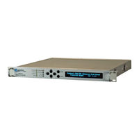
Comtech EF Data CDM-750 Installation And Operation Manual (300 pages)
Advanced High-Speed Trunking Modem
Brand:
Comtech EF Data
| Category:
Modem
| Size: 8.98 MB
Table of Contents
Table of Contents
3
Tables
12
Figures
13
Preface
15
About this Manual
15
Reporting Comments or Suggestions Concerning this Manual
15
Conventions and References
15
Patents and Trademarks
15
Warnings, Cautions, and Notes
15
Examples of Multi-Hazard Notices
16
Recommended Standard Designations
16
Metric Conversion
16
Safety and Compliance
16
Electrical Safety and Compliance
16
Electrical Installation
17
Operating Environment
17
European Union Radio Equipment and Telecommunications Terminal Equipment (R&TTE) Directive (1999/5/EC) and en 301 489-1
17
European Union Electromagnetic Compatibility (EMC) Directive (2004/108/EC)
17
European Union Low Voltage Directive (LVD) (2006/95/EC)
18
European Union Rohs Directive (2002/95/EC)
18
European Union Telecommunications Terminal Equipment Directive (91/263/EEC)
19
CE Mark
19
Warranty Policy
19
Limitations of Warranty
19
Exclusive Remedies
20
Getting Help
21
Contacting Comtech EF Data
21
Returning a Product for Upgrade or Repair
22
Functional Description
23
Figure 1-1. CDM-750 Advanced High-Speed Trunking Modem
23
Chapter 1. INTRODUCTION
23
Overview
23
Appendix H. Fec (Forward Error Correction
25
Table 1-1. FAST and FAST-Accessible Hardware Options
26
Features
27
Physical Description
28
Dimensional Envelope
29
Figure 1-2. CDM-750 Dimensional Envelope
29
External Physical Features
30
Front Panel
30
Figure 1-3. CDM-750 Front Panel View
30
Rear Panel
31
Figure 1-4. CDM-750 Rear Panel View
31
Rear Panel Standard Features
31
Rear Panel Optional Features
32
Specifications
33
System Specifications
33
Environmental and Physical
33
Base Unit Connectors
34
Test Functions
34
Modulator (Dual IF)
34
Demodulator (Dual IF)
35
Figure 1-5. 70/140 Mhz Input Level Vs. Symbol Rate
35
Adaptive Coding and Modulation (ACM)
36
Figure 1-6. L-Band Input Level Vs. Symbol Rate
36
(Cnc)
37
Regulatory Compliance
37
Standard Assemblies
37
Optional Assemblies
38
Chapter 2. INSTALLATION
39
Unpacking and Inspecting the Shipment
39
Figure 2-1. Unpacking and Inspecting the Shipment
39
Installing into a Rack Enclosure
40
Figure 2-2. Installing into a Rack Enclosure
41
Installing the Optional Rear-Mounting Support Brackets Kit
42
Figure 2-3. Installing the Optional Rear-Mounting Support Brackets Kit
42
Installing the Optional Bearingless Rack Slide Set
44
Figure 2-4. Installing the Optional Bearingless Rack Slide Set
44
Chapter 3. REAR PANEL CONNECTIONS
45
Cabling Connection Types
45
Coaxial Cable Connections
45
Figure 3-1. Coaxial Connector Examples
45
Type 'BNC
46
Type 'N
46
Type 'TNC
46
Type 'F
47
Type 'SMA' (Subminiature Version 'A')
47
D-Subminiature Cable Connections
47
Figure 3-2. D-Subminiature Connector Examples
47
Circular Cable Connections
48
Cable Connections
48
Cabling Connections
49
Figure 3-3. CDM-750 Cabling Connections
49
Table 3-1. CDM-750 Rear Panel Connectors
50
IF Connector Group
51
J10 | TX MON Connector, Type 'SMA
51
Rx Connectors
51
Tx Connectors
51
Utility Connector Group
52
J1 | ALARM Connector, DB-15M
52
J2 | REDUNDANCY Connector, DB-9F
53
J3 | REMOTE Connector, DB-9M
53
J4 | MGMT Connector, RJ-45F
54
J8 | EXT REF Connector, BNC
54
Terrestrial Data Connector Group
55
J5 | DATA, J6 | DATA Connections, RJ-45F
55
Figure 3-4. Typical SFP Module Installation
56
J7 | OPTICAL Connection, 1000Base-SX Cage
56
Optional Optical Gigabit Ethernet Interface (CEFD P/N IC-0000058)
56
PIIC Data Interface Slots
57
Ground and Power Connections
58
Chassis Ground Interface
58
Figure 3-6. CDM-750 Chassis Ground Interface
58
230V Alternating Current (AC) Power Interface (Standard)
59
AC Operation - Applying Power
59
Figure 3-7. CDM-750 AC Power Interface
59
Figure 3-8. Applying AC Power to the CDM-750
59
AC Operation - Replacing Fuses
60
Figure 3-9. Replacing CDM-750 AC Fuses
60
Direct Current (DC) Power Interface (Optional)(FUTURE)
61
Figure 3-10. CDM-750 DC Power Interface
61
DC Operation - Applying Power
62
Figure 3-11. Applying DC Power to the CDM-750
62
DC Operation - Replacing Fuses
63
Figure 3-12. Replacing CDM-750 DC Fuses
63
Chapter 4. UPDATING FIRMWARE
65
Updating Firmware Via the Internet
65
Getting Started: Preparing for the Firmware Download
66
Downloading and Extracting the Firmware Update
70
Performing the Ethernet FTP Upload Procedure
72
Chapter 5. FRONT PANEL OPERATION
77
Introduction
77
Figure 5-1. CDM-750 Front Panel View
77
LED Indicators
78
Keypad
79
Vacuum Fluorescent Display (VFD)
80
Opening Screen
80
Screen Saver
80
Front Panel Menus
81
Table 5-1. CDM-750 Front Panel Menu Matrix
81
SELECT: (Main) Menu
82
SELECT: Configuration
82
CONFIG: Intf (Configure Interface)
83
Single Stream Mode Vs. Multistream Mode Operation
84
(Config: Intf) Piicx (G703)
86
(Config: Intf) Piicx (Oc3)
90
(Config: Intf) Gbeix
93
Figure 5-2. MAC Learning Operations
95
CONFIG) INTF: Optical
96
CONFIG) Tx: Freq (Frequency)
96
CONFIG) Tx: if
96
CONFIG: Tx
96
CONFIG) Tx: Frame
97
CONFIG) Tx: Power
97
(CONFIG) Tx: Data
98
CONFIG) Tx: Mod (Modulation)
98
(CONFIG) Tx: Pilot
100
Table 5-2. Symbol Rate / Data Rate Range for Standard Fecframe (DVB-S2 Standard Fecframe = 64,800 Bits)
101
CONFIG) Rx: Frame
102
CONFIG) Rx: Freq (Frequency)
102
CONFIG) Rx: if
102
CONFIG: Rx
102
(CONFIG) Rx: Data
103
CONFIG) Rx: Mod (Modulation)
103
CONFIG) Rx: Pilot
103
CONFIG) Rx: Esno
104
CONFIG) Clocking: Freq-Ref
105
CONFIG) Clocking: Int-Ref-Adjust
105
CONFIG: Clocks
105
CONFIG) ACM Config: Min/Max-Modcod
106
CONFIG) ACM Config: Unlock-Action
106
CONFIG: ACM (Adaptive Coding and Modulation)
106
CONFIG) ACM Config: Degradation
107
CONFIG) ACM Config: Target-Es/No-Margin
107
CONFIG) Carrier-In-Carrier: Mode
109
CONFIG) Carrier-In-Carrier: Search-Delay
109
CONFIG: Cnc
109
CONFIG: Mask
110
CONFIG) Remote Control: Serial or Ser+Ethernet
111
CONFIG: Remote (Remote Control)
111
CONFIG) Remote Control: Inband
112
(CONFIG) IP Config: Addresses
113
Config: Ip
113
(CONFIG) IP Config: SNMP
114
CONFIG: Comp
116
SELECT: Test
117
Test: Bert
117
TEST: Mode
117
Figure 5-3. Loopback Test Modes
118
TEST: BERT Config
119
TEST: BERT Monitor
119
TEST: Comp
120
SELECT: Monitor
121
Monitor: Live-Alarms
121
Monitor: ACM
122
Monitor: Rx-Params (Rx Parameters)
122
Monitor: Stored-Events
122
Monitor: Cnc (Carrier-In-Carrier Parameters)
123
Monitor: Stats IP
123
Monitor: Stats (Statistics)
123
Monitor: Stats Compression
126
Monitor: Buffer
127
SELECT: Info (Information)
128
Info: ID
128
Info: Intf
128
Info: Rx
129
Info: Tx
129
Info: ACM
130
Info: Clocks
130
Info: Cnc
130
Info: Misc
130
Info: Comp
131
Info: Remote
131
SELECT: Store/Ld (Store/Load)
132
SELECT: Utility
133
Utility: Display-Brightness
133
Utility: LED
133
Utility: Set-RTC
133
Utility: 1:1
134
Utility: 1:N
134
Utility: Circuit ID
135
Utility: Firmware
135
UTILITY) Firmware Images: Select
136
SELECT: ODU (Outdoor Unit)
136
ODU) Lnb:pwrsupply+Ref: PSU-And-10Mhz
136
ODU: Lnb:pwrsupply+Ref
136
ODU) Lnb:pwrsupply+Ref: Psumonitor
137
Select: Fast
138
FAST: Options
138
FAST) FAST Options: Set
139
FAST) FAST Options: View
139
FAST: Demo-Mode
139
FAST: Cnc
140
Chapter 6. Ethernet-Based Remote Product Management
143
Introduction
143
Ethernet Management Interface Protocols
144
SNMP Interface
144
Management Information Base (MIB) Files
145
SNMP Community Strings
145
SNMP Traps
146
Telnet Interface
147
Telnet Operation Via Hyperterminal
147
Web Server (HTTP) Interface
149
User Login
149
Web Server Interface - Operational Features
150
Navigation
150
Page Sections
150
Action Buttons
150
Drop-Down Lists
150
Text or Data Entry
151
Web Server Interface - Menu Tree
151
Home | Home
152
Home | Contact and Home | Support
153
Admin | Access
154
Figure 6-3. Admin | Access Page
154
Admin | SNMP
156
Configuration | Modem
157
Configuration | Utilities
158
Configuration | Test
159
Configuration: LNB (Low Noise Block down Converter)
160
Status | Status
161
Status | Logs
162
Status | Info
163
Status | Firmware
164
Status | ACM
165
Status | IP Statistics
166
Status | BB Statistics
167
Interfaces | Ethernet
169
Interfaces | PIIC (Plug-In Interface Card)
170
Txgraph Pages (Minutes / Hours / Days)
172
Figure 6-18. Txgraph Pages (Txhours Page Shown)
172
Rxgraph Pages (Minutes / Hours / Days)
175
Figure 6-19. Rxgraph Pages (Rxhours Page Shown)
175
Chapter 7. SERIAL-BASED REMOTE PRODUCT MANAGEMENT
179
Introduction
179
Remote Commands and Queries Overview
181
Basic Protocol
181
Packet Structure
181
Target Address
182
Address Delimiter
183
Instruction Code
183
Instruction Code Qualifier
183
Optional Message Arguments
184
End of Packet
184
Remote Commands and Queries
185
Tx Parameters
188
Rx Parameters
191
IP Packet Parameters
194
Unit Parameters
196
ACM Parameters
204
PIIC Interface Parameters
205
Bulk Configuration Strings
208
ODU Parameters
210
Modem Information
211
Modem Performance Indication
215
Redundancy Control
220
Appendix A. Fast Options and Activation Procedure
221
FAST System Overview
221
FAST Activation Procedure
222
Appendix B. PIIC (PLUG-IN INTERFACE CARD) MODULES
225
Introduction
225
Typical PIIC Module Installation
226
Figure 3-5. Typical PIIC Module Installation
226
Optional PIIC Modules
228
G.703 E3/T3/STS-1 PIIC Module (CEFD P/N PL-0000795)
228
B.2.1.1.1 General Specifications
229
B.2.1.1.2 Interface Specifications
229
Copper PIIC Module Kit (CEFD P/N KT-0000255)
230
Single/Multi Mode PIIC Module Kits (CEFD P/N KT-000025X)
232
B.2.3.1 OC-3 Single/Multi Mode PIIC Module Summary of Specifications
233
Appendix C. ADAPTIVE CODING and MODULATION (ACM) OPTION
235
Introduction
235
Background
236
Table C-1. ACM Example for Standard Fecframe (64,800 Bits)
236
Table C-2. Modcod Comparison: ACM Vs. CCM
237
ACM Operational Link Example
238
Table C-3. Turning Margin into Additional Capacity
239
ACM System Description
240
ACM Scheme
242
Target Es/No Margin
242
Distortion Adaptation / Modulation Type Impairment
243
Pilots
244
Long and Short Frames
244
Monotonic Operation
244
Table C-4. Modulation Type Impairment
244
Table C-5. Spectral Efficiency and Ideal Es/No by Modcod
245
Modcod Selection
246
Configuring ACM in the CDM-750
248
Table C-6. Data Rate by Option Symbol Rate
249
ACM Configuration Via the Front Panel
250
ACM Configuration Via the CDM-750 Web Server Interface
251
Monitoring ACM Performance and Statistics
252
ACM Congestion Control
253
Notes and Recommendations
254
ACM - Summary of Specifications
255
Appendix D.Doubletalk Carrier-In-Carrier (Cnc) Option
257
Introduction
257
What Is Doubletalk Carrier-In-Carrier
257
Application Requirements
258
Operational Details
260
System Functionality and Operational Considerations
261
Table D-1. Spectral Efficiency Using Doubletalk Carrier-In-Carrier
263
Doubletalk Carrier-In-Carrier Cancellation Process
264
Margin Requirements
265
Carrier-In-Carrier Latency
265
Carrier-In-Carrier and Adaptive Coding and Modulation (ACM)
266
Carrier-In-Carrier Link Design
266
Symmetric Data Rate Link
267
Commissioning and Deploying Carrier-In-Carrier
272
Operational References
273
Calculating a Carrier-In-Carrier Link Budget
273
Estimating / Calculating Cnc Ratio
274
Calculating Cnc Ratio and PSD Ratio from Satmaster
276
Doubletalk Carrier-In-Carrier Specifications
276
Carrier-In-Carrier Summary
276
Glossary
277
Appendix E. Es/No MEASUREMENT
281
Table E-1. CDM-750 Co+No/No to C/N (Es/No) and Eb/No (Db) for DVB-S2 QPSK and 8PSK
283
Table E-2. CDM-750 Co+No/No to C/N (Es/No) and Eb/No (Db) for DVB-S2 16APSK and 32APSK
284
Appendix F. ETHERNET NETWORK CONFIGURATION
285
Introduction
285
Ethernet Routers and Switches
285
Ethernet Configuration Examples
286
Ethernet Network Overview
286
Ethernet Overview
287
Ethernet Interfaces
287
Ethernet Overhead
288
Appendix G. ETHERNET STATISTICS and STATUS REPORTING
289
Introduction
289
Data Flow Diagram
289
Statistics Items
291
Ethernet Data Statistics
291
Framing and Baseband Statistics
291
Status Items
292
BER Testing
292
ACM Modulator Status
292
ACM Demodulator Status
292
Cnc Status
292
Introduction
293
DVB-S2: LDPC and BCH
293
Range of Data Rates
294
BER, QEF, Eb/No, Es/No Spectral Efficiency, and Occupied Bandwidth
294
Advertisement
Comtech EF Data CDM-750 Installation And Operation Manual (232 pages)
Advanced High-Speed Trunking Modem
Brand:
Comtech EF Data
| Category:
Modem
| Size: 4.67 MB
Table of Contents
Table of Contents
5
Preface
15
About this Manual
15
Reporting Comments or Suggestions Concerning this Manual
15
Conventions and References
15
Metric Conversion
15
Recommended Standard Designations
15
Trademarks
15
Cautions and Warnings
16
Electrical Safety and Compliance
16
Fuses
16
Low Voltage Directive (LVD)
16
International Symbols
17
Installation
17
Environmental
17
Telecommunications Terminal Equipment Directive
17
CE Mark
17
Rohs Compliance
18
EMC (Electromagnetic Compatibility) Compliance
18
Warranty Policy
19
Limitations of Warranty
19
Exclusive Remedies
20
Customer Support
21
Online Customer Support
21
Chapter 1. INTRODUCTION
23
Overview
23
Figure 1-1. CDM-750 Advanced High-Speed Trunking Modem
23
Functional Description
24
Features
25
Physical Description
25
Major Assemblies
26
Standard Assemblies
26
Optional Assemblies
26
Dimensional Envelope
27
Figure 1-2. CDM-750 Dimensional Envelope
27
Physical Features
28
Front Panel
28
Rear Panel
28
Figure 1-3. CDM-750 Front Panel View
28
Figure 1-4. CDM-750 Rear Panel Views
28
Hardware Options
29
Standard Hardware
29
Optional Hardware
29
Data Interfaces
29
Verification
29
Flash Upgrading Modem Firmware
30
Fully Accessible System Topology (FAST)
30
Supporting Hardware and Software
31
Table 1-1. FAST and FAST-Accessible Hardware Options
31
Summary of Specifications
32
System Specifications
32
Environmental and Physical
32
Base Unit Connectors
33
Test Functions
33
Modulator (Dual IF)
33
Demodulator (Dual IF)
34
Figure 1-5. 70/140 Mhz Input Level Vs Symbol Rate
34
Adaptive Coding and Modulation (ACM)
35
Figure 1-6. L-Band Input Level Vs Symbol Rate
35
Doubletalk Carrier-In-Carrier (Cnc)
36
Approvals
36
Chapter 2. INSTALLATION
37
Unpacking and Inspection
37
Mounting
38
Method A: Optional Rear-Mounting Support Bracket Kit (KT-0000168)
38
Method B: Optional Bearingless Side-Railing Set (FP/SL0006)
39
Figure 2-1. Optional Rear-Mounting Support Bracket Kit (KT-0000168) Installation
39
Figure 2-2. Optional Bearingless Side-Railing Set (FP/SL0006) Installation
40
Figure 3-1. CDM-750 Rear Panel Views
41
Chapter 3. Rear Panel Connectors and Pinouts
42
Table 3-1. CDM-750 Rear Panel Connectors
42
J10 | TX MON Connector, Type 'SMA' ............................................................................................ 3–3
42
IF Connections
43
Rx Connectors
43
Tx Connectors
43
J10 | TX MON Connector, Type 'SMA
43
Utility Connections
44
J1 | ALARM Connector, DB-15M
44
J2 | REDUNDANCY Connector, DB-9F
44
J3 | REMOTE Connector, DB-9M
45
J4 | MGMT Connector, RJ-45F
45
J8 | EXT REF Connector, BNC
46
Terrestrial Data Connections
47
J5 | DATA, J6 | DATA Connections, RJ-45F
47
J7 | OPTICAL Connection, 1000Base-SX Cage
48
Optional Optical Gigabit Ethernet Interface (CEFD P/N IC-0000058)
48
PIIC Data Interfaces
49
E3/T3 PIIC Data Interface
49
Power / Ground Connections
50
Alternating Current Power Connector
50
Direct Current Power Connector (FUTURE)
50
Chassis Ground Connector
50
Chapter 4. FLASH UPGRADING
51
Flash Updating Via Internet
51
Figure 4-1. Flash Update Via Internet
51
Ethernet FTP Upload Procedure
52
Chapter 5. FRONT PANEL OPERATION
55
Introduction
55
Figure 5-1. CDM-750 Front Panel View
55
LED Indicators
56
Keypad
57
Vacuum Fluorescent Display (VFD)
57
Front Panel Menus
58
Opening Screen
58
Table 5-1. CDM-750 Front Panel Menu Matrix
58
Select: (Main) Menu
59
Select: Configuration
60
Config) Intf: Piicx = G703
61
CONFIG: Intf (Configure Interface)
61
Config) Intf: Gbeix
64
CONFIG) INTF: Optinst
65
CONFIG) Tx : if
66
CONFIG) Tx: Freq (Frequency)
66
CONFIG: Tx
66
CONFIG) Tx: Data
67
CONFIG) Tx: Frame
67
CONFIG) Tx: Mod (Modulation)
67
CONFIG) Tx: Power
67
CONFIG) Tx: Pilot
69
Table 5-2. Symbol Rate / Data Rate Range for Standard Fecframe (DVB-S2 Standard Fecframe = 64,800 Bits)
70
CONFIG) Rx: if
71
CONFIG: Rx
71
CONFIG) Rx: Freq (Frequency)
71
CONFIG) Rx: Frame
71
CONFIG) Rx: Mod (Modulation)
72
CONFIG) Rx: Data
72
CONFIG) Rx: Pilot
72
CONFIG) Rx: Esno
73
CONFIG: Clocks
73
CONFIG) Clocking: Freq-Ref
73
CONFIG) Clocking: Int-Ref-Adjust
73
CONFIG: ACM (Adaptive Coding and Modulation)
74
CONFIG) ACM Config: Min/Max-Modcod
74
CONFIG) ACM Config: Unlock-Action
75
CONFIG) ACM Config: Target-Es/No-Margin
75
CONFIG) ACM Config: Degradation
76
CONFIG: Cnc
76
CONFIG) Carrier-In-Carrier: Mode
76
CONFIG) Carrier-In-Carrier: Search-Delay
77
CONFIG: Mask
77
CONFIG: Remote (Remote Control)
78
CONFIG) Remote Control: Serial or Ser+Ethernet
78
CONFIG) Remote Control: Inband
79
Config: Ip
79
CONFIG) IP Config: Addresses
79
CONFIG) IP Config: SNMP
80
Snmp Communities
80
CONFIG: Comp
82
Select: Test
83
TEST: Mode
83
Test: Bert
83
Figure 5-2. Loopback Test Modes
84
TEST: BERT Config
85
TEST: BERT Monitor
85
TEST: Comp
85
Select: Monitor
86
Monitor: Live-Alarms
86
Monitor: Stored-Events
87
Monitor: ACM
87
Monitor: Rx-Params (Rx Parameters)
87
Monitor: Cnc (Carrier-In-Carrier Parameters)
88
Monitor: Stats (Statistics)
88
Monitor: Stats IP
88
Monitor: Buffer
92
Select: Info (Information)
92
Info: ID
92
Info: Intf
92
Info: Tx
93
Info: Rx
93
Info: Clocks
94
Info: ACM
94
Info: Cnc
94
Info: Misc
94
Info: Remote
94
Info: Comp
95
Select: Store/Ld (Store/Load)
95
Select: Utility
95
Utility: 1:1
96
Utility: Display-Brightness
96
Utility: LED
96
Utility: Set-RTC
96
UTILITY) Firmware Images: Info
97
Utility: Circuit ID
97
Utility: Firmware
97
FAST: Options
98
Select: FAST
98
UTILITY) Firmware Images: Select
98
FAST) FAST Options: Set
99
FAST) FAST Options: View
99
FAST: Demo-Mode
99
FAST: Cnc
100
Chapter 6. ETHERNET MANAGEMENT
101
Introduction
101
Ethernet Management Interface Protocols
101
SNMP Interface
101
Management Information Base (MIB) Files
101
SNMP Community Strings
102
SNMP Traps
102
Telnet Interface
103
Web Server (HTTP) Interface
105
Interface Introduction
105
Interface Access
105
Interface Menu Tree
106
Home | Home .............................................................................................................. 6–7
106
Web Server Interface
107
Home
107
Figure 6-1. CDM-750 Home Page
107
Home | Home
107
Figure 6-2. Home | Contact Information Page
108
Home | Contact
108
Figure 6-3. Home | Customer Support Page
109
Home | Support
109
Admin (Administration)
110
Admin | Access
110
Figure 6-4. Admin | Access Page
110
Admin | SNMP
112
Figure 6-5. Admin | SNMP Page
112
Configuration
113
Configuration | Modem
113
Figure 6-6. Configuration | Modem Page
113
Configuration | Utilities
114
Figure 6-7. Configuration | Utilities Page
114
Status
116
Figure 6-8. Status | Status Page
116
Status | Status
116
Figure 6-9. Status | Logs Page
117
Status | Logs
117
Figure 6-10. Status | Info Page
118
Status | Info
118
Figure 6-11. Status | Firmware Info Page
119
Status | Firmware
119
Figure 6-12. Status | ACM Status Page
120
Status | ACM
120
Figure 6-13. Status | IP Statistics Page
121
Status | IP Statistics
121
Figure 6-14. Status | BB Statistics Page
122
Status | BB Statistics
122
Interfaces Page
123
Figure 6-15. Interfaces Page
123
Txgraph Pages (Minutes / Hours / Days)
125
CDM-750 Advanced High-Speed Trunking Modem Revision
125
Rxgraph Pages (Minutes / Hours / Days)
128
Figure 6-17. Rxgraph Pages (Rxhours Page Shown)
128
Chapter 7. ADAPTIVE CODING and MODULATION (ACM) OPTION
131
Introduction
131
Background
132
Table 7-1. ACM Example for Standard Fecframe (64,800 Bits)
132
Example of ACM Operational Link
133
Table 7-2. Modcod Comparison: ACM Vs. CCM
133
Figure 7-1. Downlink Margin Vs. Average Link Availability
134
ACM System Description
135
Table 7-3. Turning Margin into Additional Capacity
135
Figure 7-3. ACM-Over-Satellite – Generic Example
136
ACM Scheme
137
Target Es/No Margin
137
Distortion Adaptation / Modulation Type Impairment
138
Table 7-4. Modulation Type Impairment
138
Pilots
139
Long and Short Frames
139
Monotonic Operation
140
Table 7-5. Spectral Efficiency and Ideal Es/No by Modcod
140
Modcod Selection
141
Figure 7-5. Spectral Efficiency Vs. Ideal Es/No @ QEF
141
Figure 7-6. Spectral Efficiency Vs. Modem Es/No @ QEF (Pruned Modcods)
142
Configuring ACM in the CDM-750
143
Table 7-6. Data Rate by Option Symbol Rate
144
ACM Configuration Via the Front Panel
145
Monitoring ACM Performance and Statistics
145
ACM Congestion Control
146
Figure 7-7. CDM-750 – ACM Congestion Control
146
Notes and Recommendations
147
ACM - Summary of Specifications
148
Chapter 8. Doubletalk Carrier-In-Carrier Option
149
Introduction
149
What Is Doubletalk Carrier-In-Carrier
149
Application Requirements
150
Figure 8-1. Conceptual Block Diagram
151
Operational Details
152
System Functionality and Operational Considerations
153
Figure 8-2. Conventional FDMA Link
153
Figure 8-3. same Link Using CDM-750 and Doubletalk Carrier-In-Carrier
154
Table 8-1. Spectral Efficiency Using Doubletalk Carrier-In-Carrier
155
Doubletalk Carrier-In-Carrier Cancellation Process
156
Figure 8-5. Doubletalk Carrier-In-Carrier Signals
156
Carrier-In-Carrier and Adaptive Coding and Modulation (ACM)
157
Carrier-In-Carrier Latency
157
Figure 8-6. Carrier-In-Carrier Signal Processing Block Diagram
157
Margin Requirements
157
Carrier-In-Carrier Link Design
158
Symmetric Data Rate Link
158
Asymmetric Data Rate Link
160
Power Limited Links
161
Carrier-In-Carrier Commissioning and Deployment
162
Operational References
163
Carrier-In-Carrier Link Budget Calculation
163
Estimating / Calculating Cnc Ratio
164
Estimating Cnc Ratio from LST / EIRP
164
Calculating Cnc Ratio from Carrier to Noise Ratio (C/N) on a Spectrum Analyzer
165
Calculating Cnc Ratio and PSD Ratio from Satmaster
166
Doubletalk Carrier-In-Carrier Specifications
166
Carrier-In-Carrier Summary
166
Glossary
167
Chapter 9. ETHERNET NETWORK CONFIGURATION
171
Introduction
171
Ethernet Routers and Switches
171
Ethernet Configuration Examples
172
Ethernet Network Overview
172
Ethernet Overview
172
Ethernet Interfaces
172
Figure 9-1. Networking Loop with Switches
172
Ethernet Overhead
173
Figure 9-2. CDM-750 Ethernet Architecture Design
173
Chapter 10. FORWARD ERROR CORRECTION
175
Introduction
175
LDPC and BCH
175
Range of Data Rates
176
BER, QEF, Eb/No, Es/No Spectral Efficiency, and Occupied Bandwidth
176
Figure 10-1. DVB-S2 QPSK Packet Error Rate Versus Es/No
177
Figure 10-2. DVB-S2 8PSK Packet Error Rate Versus Es/No
178
Figure 10-3. DVB-S2 16APSK Packet Error Rate Versus Es/No
179
Figure 10-4. DVB-S2 32APSK Packet Error Rate Versus Es/No
180
Chapter 11 .G.703 E3/T3/Sts-1 Plug-In Interface Card (Piic)
181
Introduction
181
Figure 11-1. G.703 E3/T3/STS-1 Plug-In Interface Card (PIIC)
181
Physical Description
182
Figure 11-2. G.703 E3/T3/STS-1 PIIC Block Diagram
182
E3/T3/STS-1 PIIC Connectors and Pinouts
183
Installing the G.703 E3/T3/STS-1 PIIC
183
Summary of Specifications
184
General Specifications
184
Interface Specifications
184
Appendix A. Es/No MEASUREMENT
185
Table A-1. CDM-750 Co+No/No to C/N (Es/No) and Eb/No (Db) for DVB-S2 QPSK and 8PSK
187
Table A-2. CDM-750 Co+No/No to C/N (Es/No) and Eb/No (Db) for DVB-S2 16APSK and 32APSK
188
Appendix B. Ethernet Statistics and Status Reporting
189
Introduction
189
Data Flow Diagram
189
Figure B-1. CDM-750 Data Flow Diagram
190
Statistics Items
191
Ethernet Data Statistics
191
Framing and Baseband Statistics
191
Status Items
192
BER Testing
192
ACM Modulator Status
192
ACM Demodulator Status
192
Cnc Status
192
Appendix C. FAST ACTIVATION PROCEDURE
193
FAST System Overview
193
FAST Activation Procedure
194
Record Modem Serial Number
194
View Currently Installed Features
194
Order FAST Options
195
Enter FAST Access Code
195
Appendix D. REMOTE CONTROL
197
Overview
197
Basic Protocol
198
Packet Structure
199
Start of Packet
199
Target Address
199
Address Delimiter
200
Instruction Code
200
Instruction Code Qualifier
200
Optional Message Arguments
201
End of Packet
201
Remote Commands and Queries
202
Tx Parameters
203
Rx Parameters
207
IP Packet Parameters
210
Unit Parameters
212
ACM Parameters
219
Parameters
219
Bulk Configuration Strings
222
Modem Information
224
Modem Performance Information
227
Metric Conversions
231
Advertisement
Related Products
Comtech EF Data CDM-700
Comtech EF Data CDM-710
Comtech EF Data CDM-710L
Comtech EF Data CDM-710G
Comtech EF Data CDM-740
Comtech EF Data CDM-760
Comtech EF Data CDM-600
Comtech EF Data CDM-625A
Comtech EF Data CDM-2020
Comtech EF Data CDM-550T
Comtech EF Data Categories
Modem
Switch
Amplifier
Network Router
Media Converter
More Comtech EF Data Manuals
Login
Sign In
OR
Sign in with Facebook
Sign in with Google
Upload manual
Upload from disk
Upload from URL