Table of Contents
Advertisement
Quick Links
CDM-700
High Speed Satellite Modem
Installation and Operation Manual
IMPORTANT NOTE: The information contained in this document supersedes all previously published
information regarding this product. Product specifications are subject to change without prior notice.
Part Number MN/CDM700.IOM
Revision 5
Advertisement
Table of Contents

Related Manuals for Comtech EF Data CDM-700


Summary of Contents for Comtech EF Data CDM-700
-
Page 1: Installation And Operation Manual
CDM-700 High Speed Satellite Modem Installation and Operation Manual IMPORTANT NOTE: The information contained in this document supersedes all previously published information regarding this product. Product specifications are subject to change without prior notice. Part Number MN/CDM700.IOM Revision 5... - Page 3 High-Speed Satellite Modem Installation and Operation Manual Part Number MN/CDM700.IOM Revision 5 December 12, 2008 Copyright © 2008 Comtech EF Data. All rights reserved. Printed in the USA. Comtech EF Data, 2114 West 7th Street, Tempe, Arizona 85281 USA, 480.333.2200, FAX: 480.333.2161...
-
Page 5: Table Of Contents
Table of Contents PREFACE ..........................XV Customer Support ............................. xv About this Manual ........................... xvi Reporting Comments or Suggestions Concerning this Manual ............. xvi Conventions and References ........................xvi Metric Conversion ..........................xvi Cautions and Warnings .......................... xvi Recommended Standard Designations ....................xvi Electrical Safety ............................ - Page 6 CDM-700 High-Speed Satellite Modem Revision 5 Table of Contents MN/CDM700.IOM 1.6 New in This Release ........................1–6 CHAPTER 2. INSTALLATION ....................2–1 2.1 Unpacking and Inspection ......................2–1 2.2 Mounting ............................2–2 2.2.1 Method A: Optional Rear-Mounting Support Brackets ............2–2 ...
- Page 7 CDM-700 High-Speed Satellite Modem Revision 5 Table of Contents MN/CDM700.IOM 5.1.7 RS-232/485 Remote Port Connector Pinout – P2 ..............5–7 5.2 Data Interfaces ..........................5–7 CHAPTER 6. FRONT PANEL OPERATION ................. 6–1 6.1 Introduction ..........................6–1 6.1.1 Front Panel LED Indicators ....................6–2 ...
- Page 8 CDM-700 High-Speed Satellite Modem Revision 5 Table of Contents MN/CDM700.IOM Intfc1 HSSI: CTS/RTS ......................6–37 Intfc1 HSSI: Alarm ........................ 6–38 6.3.1.6.1 (CONFIG:) Intfc2 (CDI-60 HSSI Interface) ............. 6–38 6.3.1.7 (CONFIG:) Intfc1 (CDI-70 Gigabit Ethernet Interface) ..........6–38 Intfc1 Gigabit Ethernet: Tx ....................
- Page 9 CDM-700 High-Speed Satellite Modem Revision 5 Table of Contents MN/CDM700.IOM 7.3 End-to-End Processing Delay (Latency) ................... 7–3 CHAPTER 8. CLOCK MODES ..................... 8–1 8.1 Introduction ..........................8–1 8.2 CDI-10 Dual G.703 Interface ..................... 8–3 8.2.1 CDI-10 Dual G.703 Interface Transmit Clocking ..............8–3 ...
- Page 10 11.6 Remote Commands and Queries ..................... 11–6 CHAPTER 12. SNMP INTERFACE ..................12–1 12.1 SNMP Interface ......................... 12–1 12.2 CDM-700 Management Information Base (MIB) Files ............12–2 12.3 SNMP Community Strings ....................... 12–3 12.4 CDM-700 Common Private MIB ..................... 12–3 ...
- Page 11 CDM-700 High-Speed Satellite Modem Revision 5 Table of Contents MN/CDM700.IOM 12.10 CDM Redundancy Objects ....................12–5 12.11 SNMP Traps .......................... 12–5 12.12 MIB-II ............................ 12–6 CHAPTER 13. TELNET INTERFACE ................. 13–1 13.1 Telnet Interface ......................... 13–1 13.2 Caution Using Windows Telnet Client ..................13–3 ...
- Page 12 CDM-700 High-Speed Satellite Modem Revision 5 Table of Contents MN/CDM700.IOM 15.5.1 Config Mdm: Modem Page ....................15–8 15.5.2 Config Mdm: Modem Utilities Page ................... 15–9 15.5.3 Config Mdm: INTF1 (Interface 1) Page ................15–10 15.5.3.1 Config Mdm: INTF1 – E3/T3/STS1 Page ..............15–11 ...
- Page 13 CDM-700 High-Speed Satellite Modem Revision 5 Table of Contents MN/CDM700.IOM D.4 Environmental And Physical ....................D–5 D.5 Connector Pinout ........................D–6 APPENDIX E. 10/100/1000 BASE-T INTERFACE (GBEI) (CDI-70) ........E–1 E.1 Introduction ..........................E–1 E.2 Physical Description ........................E–2 E.3 ...
- Page 14 Figure 6-2. Keypad ............................ 6–3 Figure 6-3. Traffic Flow Loopback Block Diagrams ................6–59 Figure 7-1. CDM-700 Gigabit Ethernet Latency with Modem in IF Loopback .......... 7–4 Figure 7-2. CDM-700 HSSI Latency with Modem in IF Loopback ............7–4 ...
- Page 15 CDM-700 High-Speed Satellite Modem Revision 5 Table of Contents MN/CDM700.IOM Figure 15-14. Config Mdm: INTF2 GBEI Statistics Page ..............15–16 Figure 15-15. Config Mdm: INTF2 GBEI VLAN Feature Page ............15–17 Figure 15-16. Statistics: (Main) Modem Status Page ................15–18 ...
- Page 16 CDM-700 High-Speed Satellite Modem Revision 5 Table of Contents MN/CDM700.IOM Notes:...
-
Page 17: Preface
Tempe, Arizona 85281 USA 480.333.2200 (Main Comtech EF Data number) 480.333.4357 (Customer Support Desk) 480.333.2161 FAX To return a Comtech EF Data product (in-warranty and out-of-warranty) for repair or replacement: • Contact the Comtech EF Data Customer Support Department. Be prepared to supply the Customer Support representative with the model number, serial number, and a description of the problem. -
Page 18: About This Manual
MN/CDM700.IOM About this Manual This manual provides installation and operation information for the Comtech EF Data CDM-700 High Speed Satellite Modem. This is a technical document intended for earth station engineers, technicians, and operators responsible for the operation and maintenance of the CDM-700. -
Page 19: Electrical Safety
The equipment is not designed for connection to power system that has no direct connection to ground. The CDM-700 is shipped with a line inlet cable suitable for use in the country of operation. If it is necessary to replace this cable, ensure the replacement has an equivalent specification. Examples of acceptable ratings for the cable include HAR, BASEC and HOXXX-X. -
Page 20: Telecommunications Terminal Equipment Directive
In accordance with the Telecommunications Terminal Equipment Directive 91/263/EEC, this equipment should not be directly connected to the Public Telecommunications Network. CE Mark Comtech EF Data declares that the CDM-700 Modem meets the necessary requirements for the CE Mark. RoHS Compliancy This unit satisfies (with exemptions) the requirements specified in the European Union Directive on the Restriction of Hazardous Substances, Directive 2002/95/EC, (EU RoHS). - Page 21 CDM-700 High Speed Satellite Modem Revision 5 Preface MN/CDM700.IOM Additionally, the CDM-700 has been shown to comply with the following standards: EN 61000-3-2 Harmonic Currents Emission EN 61000-3-3 Voltage Fluctuations and Flicker EN 61000-4-2 ESD Immunity EN 61000-4-4 EFT Burst Immunity...
-
Page 22: Warranty Policy
During the warranty period, Comtech EF Data will, at its option, repair or replace products that prove to be defective. For equipment under warranty, the owner is responsible for freight to Comtech EF Data and all related customs, taxes, tariffs, insurance, etc. -
Page 23: Exclusive Remedies
The buyer shall pass on to any purchaser, lessee, or other user of Comtech EF Data Corporation’s products, the aforementioned warranty, and shall indemnify and hold harmless... - Page 24 CDM-700 High Speed Satellite Modem Revision 5 Preface MN/CDM700.IOM Notes: xxii...
-
Page 25: Chapter 1. Introduction
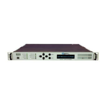
Chapter 1. INTRODUCTION Overview The Comtech EF Data CDM-700 High Speed Satellite Modem (Figure 1-1) – hereinafter referred to as “the modem” – is intended for simplex or duplex operations with a range of multi-port data interfaces. The modem operates in broadcast, circuit restoration, point-to-point and point-to-multipoint applications. -
Page 26: Standard Features
Revision 5 Introduction MN/CDM700.IOM Standard Features The CDM-700 is a high data-rate satellite modem, intended for simplex or duplex operation. The following features are available in the modem: • Compact: 1 RU, 22 inches (56 cm) deep with low power consumption •... -
Page 27: Turbo Product Coding (Tpc)
PL/11509-1 module via the Gigabit Ethernet port.) Allowable Data Interface Combinations Data interfaces are plugged into Slot 1 and Slot 2 of the CDM-700. The allowable combination of data interfaces and the data interfaces that are supported for redundancy are listed below. The... - Page 28 CDM-700 that are supported by the CRS-170A and CRS-180. First, the 1:1 switch is selected depending upon the operating frequency, and then a data interface kit for Slot 1 and Slot 2 is chosen.
-
Page 29: Fast And Hardware Options
MN/CDM700.IOM FAST and Hardware Options The CDM-700 is extremely flexible and powerful, and incorporates a large number of optional features. Comtech EF Data provides Fully Accessible System Topology (FAST), which permits the purchase and installation of options through special authorization codes, entered remotely, or through the front panel. -
Page 30: New In This Release
CDM-700 High Speed Satellite Modem Revision 5 Introduction MN/CDM700.IOM New in This Release Revision 5: • Chapter 6: Incorporated GBEI Statistics Summary, Intfc1 GBEI Negotiation added, Monitor Rx-Params updated with GBEI Frame Rate (FER1 or 2) • Chapter 10: Incorporated Power Consumption specification change •... -
Page 31: Chapter 2. Installation
Chapter 2. INSTALLATION Unpacking and Inspection The CDM-700 modem and its Installation and Operation Manual are packaged and shipped in a pre-formed, reusable cardboard carton containing foam spacing for maximum shipping protection. Do not use any cutting tool that will extend more than 1” into the container and cause damage to the unit. -
Page 32: Mounting
MN/CDM700.IOM Mounting If the CDM-700 is to be mounted in a rack, ensure that there is adequate clearance for ventilation, particularly at the sides. In rack systems where there is high heat dissipation, forced air-cooling must be provided by top or bottom mounted fans or blowers. Under no circumstance should the highest internal rack temperature be allowed to exceed 50°C (122°F). -
Page 33: Figure 2-1. Installation Of Optional Rear-Mounting Support Brackets (Kit Kt/6228-2)
CDM-700 High Speed Satellite Modem Revision 5 Installation MN/CDM700.IOM Equipment Rack Rear Mounting Rail #10 Shoulder Screw Support Bracket #10 Flat Washer #10 Flat Washer #10 Bracket Bolt #10 Split Washer #10 Hex Nut Back of unit Figure 2-1. Installation of Optional Rear-Mounting Support Brackets (Kit KT/6228-2) -
Page 34: Method B: Optional Installation Of Side-Railings
CDM-700 High Speed Satellite Modem Revision 5 Installation MN/CDM700.IOM 2.2.2 Method B: Optional Installation of Side-Railings Figure 2-2 depicts installation , of the optional side-railings (FP/SL0006), using standard shop tooling and customer-furnished standard shop hardware: Side-railings FP/SL0006 (Optional) Quantity Part Number... -
Page 35: Chapter 3. Functional Description
Chapter 3. FUNCTIONAL DESCRIPTION Description The CDM-700 has two fundamentally different types of interfaces - IF and data. • The IF interface provides interface with the satellite via the uplink and downlink equipment and will operate in full duplex or simplex modes. - Page 36 DTE equipment. Physically, the CDM-700 modem comprises several main card assemblies. Refer to Figure 3-1 for a functional block diagram. •...
-
Page 37: Interfaces Modules
1.5 to 70 CDI-70 1000 Base-T Gigabit Ethernet Interface (GbEI) 1.5 to 155.52 Figure 3-1. CDM-700 Modem Block Diagram Operating with multiple interfaces allows greater efficiency: • The transponder operates with less backoff and at higher efficiency with a single-carrier and this translates into higher throughput. -
Page 38: Data Interfaces And Data Transfer Across The Link
Simplex and Asymmetric Operation The CDM-700 is available in a full duplex or Rx only configuration, and mixing of 70/140 MHz and L-Band in the same chassis is not allowed. Most of the interfaces allow turning off the Tx or Rx side of the data interface, and this configures the disabled port to 0 Mbps. -
Page 39: Allowable Data Interfaces In Slot 1 And Slot 2
CDM-700 High Speed Satellite Modem Revision 5 Functional Description MN/CDM700.IOM Allowable Data Interfaces In Slot 1 and Slot 2 Interfaces are allowed in Slot 1 and Slot 2 as follows: Slot 1 Slot 2 CDI-10 Dual G.703 None CDI-10 Dual G.703 CDI-10 (Dual G.703) - Page 40 CDM-700 High Speed Satellite Modem Revision 5 Functional Description MN/CDM700.IOM Notes: 3–6...
-
Page 41: Chapter 4. Physical Description
DESCRIPTION Introduction The CDM-700 is constructed as a 1RU high rack-mounting chassis, which can be freestanding, if desired. Rack handles at the front facilitate removal from and placement into a rack. Figure 4-1 shows the front panel of the modem. -
Page 42: Front Panel
MN/CDM700.IOM Front Panel The CDM-700 front panel features a Vacuum Fluorescent Display (VFD), a keypad, eight Light- Emitting Diode (LED) indicators, and a Universal Serial Bus (USB) port. The user enters data via the keypad, and messages are displayed on the VFD. The LEDs indicate, in a summary fashion, the status of the unit. -
Page 43: Rear Panel
Slot 1 Chassis – Rev. A and later versions Figure 4-2. CDM-700 Rear Panel 4.3.1 External Cables External cables are attached to connectors on the rear panel of the CDM-700. These comprise: • IEC Line Input connector • Tx and Rx IF Connectors (depends upon 70/140 MHz or L-Band) •... -
Page 44: Rx And Tx If Connectors (J1 And J3)
CDM-700 High Speed Satellite Modem Revision 5 Physical Description MN/CDM700.IOM 4.3.3 Rx and Tx IF Connectors (J1 and J3) These connectors depend upon whether 70/140 or L-Band operation is chosen. Refer to Chapter 5. 4.3.4 10/100 Ethernet Remote Port Connector (J4) The Ethernet connector is a RJ45 type female. -
Page 45: Dimensional Envelope
CDM-700 High Speed Satellite Modem Revision 5 Physical Description MN/CDM700.IOM Dimensional Envelope Figure 4-3. CDM-700 Dimensional Envelope (70/140 MHz) 4–5... - Page 46 CDM-700 High Speed Satellite Modem Revision 5 Physical Description MN/CDM700.IOM Notes: 4–6...
-
Page 47: Chapter 5. Connector Pinouts
Chapter 5. CONNECTOR PINOUTS External Connections External cables are attached to connectors on the rear panel of the CDM-700. Figure 5-1 shows the CDM-700 rear panel – both current and original chassis configurations – with typical data interfaces installed in Slot 1 and Slot 2. - Page 48 CDM-700 High Speed Satellite Modem Revision 5 Connector Pinouts MN/CDM700.IOM Modem Rear Panel Connectors Table for Initially Released Chassis Version: Ref. Name Connector Type Function Des. BNC Female 70/140 MHz IF Output Tx IF Output Type N Female L-Band IF Output...
-
Page 49: 10/100 Ethernet Management Port Connector Pinout - J4
CDM-700 High Speed Satellite Modem Revision 5 Connector Pinouts MN/CDM700.IOM 5.1.1 Tx / Rx Connector Pinout – J1 / J3 The J1 (Tx) and J3 (Rx) IF interfaces are as follows: 70/140 MHz L-Band Ref. Description Des. Connector Type Connector Type... -
Page 50: Async Connector Pinout - J6 (Rev. A And Later Chassis)
CDM-700 High Speed Satellite Modem Revision 5 Connector Pinouts MN/CDM700.IOM 5.1.4 ASYNC Connector Pinout – J6 (Rev. A and Later Chassis) The J6 ASYNC Channel interface is a 9-pin, Type D female connector. Pin # Description Direction Ground RS-232 Transmit Data... -
Page 51: Alarm Connector Pinout - P1
CDM-700 High Speed Satellite Modem Revision 5 Connector Pinouts MN/CDM700.IOM 5.1.6 Alarm Connector Pinout – P1 The P1 Alarm interface is a 15-Pin type ‘D’ male connector with threaded jack nuts. The pinout depends upon whether the unit is in Normal mode, or in Redundancy mode for use with the CRS-170A (L-Band), CRS-180 (70/140 MHz), CRS-300, or CRS-700 redundancy switches. - Page 52 CDM-700 High Speed Satellite Modem Revision 5 Connector Pinouts MN/CDM700.IOM The pinout table for the P1 connector in Redundancy mode is as follows: Alarm Connector Pinout P1 – Redundancy Mode [ 1:1 (CRS-170A, CRS-180) and 1:N (CRS-300/700) ] Pin #...
-
Page 53: Rs-232/485 Remote Port Connector Pinout - P2
CDM-700 High Speed Satellite Modem Revision 5 Connector Pinouts MN/CDM700.IOM 5.1.7 RS-232/485 Remote Port Connector Pinout – P2 The P2 Remote interface is a 9-Pin type ‘D’ male connector with threaded jack nuts. Pin # Description Direction Ground RS-232 Transmit Data... - Page 54 CDM-700 High Speed Satellite Modem Revision 5 Connector Pinouts MN/CDM700.IOM Notes: 5–8...
-
Page 55: Chapter 6. Front Panel Operation
Display (VFD) Figure 6-1. Front Panel View Operators can fully control and monitor the operation of the CDM-700 from the front panel using the keypad and display. Nested menus display all available options, prompting operators to carry out a required action. -
Page 56: Front Panel Led Indicators
Front Panel Operation MN/CDM700.IOM 6.1.1 Front Panel LED Indicators The behavior of the eight front panel LEDs adjacent to the keypad indicate the operational status of the CDM-700, and are described below in Table 6-1. Table 6-1. Front Panel LED Indicators Color... -
Page 57: Front Panel Keypad
CDM-700 High Speed Satellite Modem Revision 5 Front Panel Operation MN/CDM700.IOM 6.1.2 Front Panel Keypad The front panel keypad, with its physical variations, is shown in Figure 6-2: Diamond Keypad: Button Keypad: Initially Released Chassis Rev. A or Later Chassis Figure 6-2. -
Page 58: Front Panel Vacuum Flourescent Display (Vfd)
As shown above, the ‘welcome screen’ is displayed whenever power is first applied to the unit. The top line identifies the unit model (i.e., CDM-700); the bottom line displays the CDM-700’s installed Firmware Version (version number varies). -
Page 59: Menu Matrix
CDM-700 High Speed Satellite Modem Revision 5 Front Panel Operation MN/CDM700.IOM 6.1.4 Menu Matrix Para Title Selectable Params Opening Screen SELECT: (Main) Menu Config; Monitor; Test; Info, Save/Load; Util 6.3.1 (SELECT:) Config [Configuration] Remote; Tx; Rx; Intfc1; Intfc2; Ref, AUX 6.3.1.1... -
Page 60: Opening Screen
CDM-700 High Speed Satellite Modem Revision 5 Front Panel Operation MN/CDM700.IOM Opening Screen The opening ‘welcome screen’ shown here is representative of what displays whenever power is first applied to the unit (the Firmware Version may differ). Pressing any key displays the top-level Select menu. -
Page 61: Select:) Config
CDM-700 High Speed Satellite Modem Revision 5 Front Panel Operation MN/CDM700.IOM 6.3.1 (SELECT:) CONFIG CONFIG: Remote Tx Intfc1 Intfc2 Ref Aux The submenus available are: Selection Submenu Description [Remote Control] - used to define whether the unit is controlled locally or Remote remotely. -
Page 62: Config:) Remote
CDM-700 High Speed Satellite Modem Revision 5 Front Panel Operation MN/CDM700.IOM 6.3.1.1 (CONFIG:) Remote Remote Control: Local Serial Ethernet Select Local, Serial or Ethernet by using the ◄ ► arrow keys, then press ENTER Selection Action Remote control is disabled. Remote monitoring is still possible. -
Page 63: Remote Control: Ethernet
CDM-700 High Speed Satellite Modem Revision 5 Front Panel Operation MN/CDM700.IOM If M&C Bus Interface RS232 is selected: In RS232 Mode the Bus Address is fixed at 0000 If M&C Bus Interface RS485-2W or RS485-4W is selected, further prompting occurs: RS485 Bus Address: 0001 Edit the RS485 bus address of the modem by selecting the digit to be edited, using the ◄... -
Page 64: Snmp Community
CDM-700 High Speed Satellite Modem Revision 5 Front Panel Operation MN/CDM700.IOM If Ethernet Config: Address is selected: Ethernet IP Address/Range: 010.006.030.139/16 ( The operator uses this menu to set the modem’s management IP address and subnet mask (range). This is the address used by external applications to access and control the modem using the SNMP, HTTP or Telnet interfaces. - Page 65 CDM-700 High Speed Satellite Modem Revision 5 Front Panel Operation MN/CDM700.IOM If Community Read is selected: Read Community: ( public Edit the Read Community string using the ◄ ► arrow keys. Only the bottom line (0 to 20 ▲ ▼...
-
Page 66: Config:) Tx
CDM-700 High Speed Satellite Modem Revision 5 Front Panel Operation MN/CDM700.IOM 6.3.1.2 (CONFIG:) Tx Tx: Mod Code Freq Data Sym Pwr Scram The modem symbol rate is a function of the modulation type, code rate, and data rate. If a change to one of these parameters produces a value outside the allowable symbol rate range, the invalid symbol rate is not programmed into the modem. -
Page 67: Tx: Code
CDM-700 High Speed Satellite Modem Revision 5 Front Panel Operation MN/CDM700.IOM If Tx Modulation Inv is selected: Tx Spectrum: Normal Inverted When Normal is selected the spectral sense of the carrier has the default transition to I and Q constellation points. Selecting Inverted causes the I and Q transition points to move in the opposite sense. -
Page 68: Tx: Freq
CDM-700 High Speed Satellite Modem Revision 5 Front Panel Operation MN/CDM700.IOM Freq Tx Freq: 0140.0000 MHz Edit the Tx IF Frequency by selecting the digit to be edited, using the ◄ ► arrow keys. The value of the digit is then changed using the ▲ ▼ arrow keys. Press ENTER. -
Page 69: Tx: Sym
CDM-700 High Speed Satellite Modem Revision 5 Front Panel Operation MN/CDM700.IOM Tx Sym Rate: 34.368000 Msps This is a ‘read only’ status window that displays the Symbol Rate. Refer to the detailed explanation provided under (CONFIG:) Tx Data. The symbol rate shown in this example is for a composite data rate of 34.368 Mbps (E3) when the modulation is QPSK and the code rate is 3/4. -
Page 70: Tx: Scram
CDM-700 High Speed Satellite Modem Revision 5 Front Panel Operation MN/CDM700.IOM If Tx Output State Rx-Tx_Inhibit is selected: Prevents the Tx carrier from being transmitted, until the demodulator is locked. To avoid the Tx Carrier from being turned Off when the demodulator loses Rx–Tx... -
Page 71: Config:) Rx
CDM-700 High Speed Satellite Modem Revision 5 Front Panel Operation MN/CDM700.IOM 6.3.1.3 (CONFIG:) Rx Rx: Dem Code Freq Data Sym Descrm EbNo Mask ( The modem symbol rate is a function of the modulation type, code rate, and data rate. If a change to one of these parameters produces a value outside the allowable symbol rate range, the invalid symbol rate is not programmed into the modem. - Page 72 CDM-700 High Speed Satellite Modem Revision 5 Front Panel Operation MN/CDM700.IOM If Rx Dem: Inv is selected: Rx Spectrum: Normal Inverted Select Normal or Inverted using the ◄ ► arrow keys. Press ENTER When Normal is selected, the spectral sense of the carrier has the default transition to I and Q constellation points.
-
Page 73: Rx: Code
CDM-700 High Speed Satellite Modem Revision 5 Front Panel Operation MN/CDM700.IOM Code Code Rate: 3/4 • All possible choices are presented at all times. • If an option is not installed (either Hardware or FAST) or is not valid, or if a code rate is not available for the Mode selected, the ◄... -
Page 74: Rx: Sym
CDM-700 High Speed Satellite Modem Revision 5 Front Panel Operation MN/CDM700.IOM Composite Data Rate = ∑ Port-Data Rates, where: Ports = all enabled ports for Intfc1 and Intfc2 and depends upon the interfaces installed in Slot 1 and Slot 2. - Page 75 CDM-700 High Speed Satellite Modem Revision 5 Front Panel Operation MN/CDM700.IOM If Eb/No Alarm: Threshold is selected: Eb/No Alarm Threshold: 2.0 dB ▲ ▼ E) Select a value here, and if the Eb/No falls below this value, a receive traffic fault will be generated.
-
Page 76: Config): Intfc1
6.3.1.4 (CONFIG): Intfc1 1. INFORMATION RE: ALLOWABLE INTERFACE COMBINATIONS/CONFIGURATIONS: The combination of installed data interfaces in CDM-700 Chassis Slot 1 (Intfc1) and Slot 2 (Intfc2) drive the appearance/selection of the CONFIG: Intfc1 and CONFIG: IMPORTANT Intfc2 menus. Refer to Chapter 3.3 Allowable Data Interfaces In Slot 1 and Slot 2 for a table of the available data interface combinations. -
Page 77: Intfc1 (Cdi-10 Dual G.703 Interface)
CDM-700 High Speed Satellite Modem Revision 5 Front Panel Operation MN/CDM700.IOM Intfc1 (CDI-10 Dual G.703 Interface) Interface Slot 1 Slot 2 CDI-10 Dual G.703 (E3/T3/STS1) Installed CDI-10 Dual G.703 or None Intfc1 E3/T3/STS1: Alarm Port1 Port2 Ext-Clk ◄ ► Select Alarm, Port1, Port2 or Ext-Clk using the arrow keys. - Page 78 CDM-700 High Speed Satellite Modem Revision 5 Front Panel Operation MN/CDM700.IOM Upon entering the menu, the cursor blinks below the currently active interface and its data rate is shown: Port Type Selection Data Rate 34.368 Mbps 44. 768 Mbps 51.85 Mbps...
- Page 79 CDM-700 High Speed Satellite Modem Revision 5 Front Panel Operation MN/CDM700.IOM Tx Data Alarm: Alarm Fault Mask This selection affects the event reporting status upon detection of loss of Tx Cable, and subsequently the switching logic, when the modem is in a 1:1 redundancy configuration.
- Page 80 CDM-700 High Speed Satellite Modem Revision 5 Front Panel Operation MN/CDM700.IOM Comp Tx Data/Sym Rate: 034.36800/23.484800 This display shows the Composite Tx Data Rate (Mbps) that is the sum of all enabled terrestrial ports. The Symbol Rate (Msps) is the IF Symbol Rate based on the Composite Data Rate, Overhead, Modulation, and Coding.
- Page 81 CDM-700 High Speed Satellite Modem Revision 5 Front Panel Operation MN/CDM700.IOM Buffer Slip Alarm: Alarm Fault Mask This selection will affect the event reporting status upon detection of a Buffer Slip condition, and subsequently the switching logic, when the modem is in a 1:1 redundancy configuration.
- Page 82 CDM-700 High Speed Satellite Modem Revision 5 Front Panel Operation MN/CDM700.IOM If Intfc1 Port1 Rx: Buf is selected: Intfc1 Port1 Rx Buffer: Frame-Type Size ReCenter ◄ ► Select Frame-Type, Size, or Recenter using the arrow keys. Press ENTER If Intfc1 Port1 Rx Buffer:...
- Page 83 CDM-700 High Speed Satellite Modem Revision 5 Front Panel Operation MN/CDM700.IOM If Intfc1 Port1 Rx Buffer: ReCenter is selected: Intfc1 Port1 Rx Buffer: (65%) Re-Center ◄ ► The percentage (65%) indicates the current buffer fill status. Select Re-Center, using the arrow keys, to reset the buffer to the midpoint (50%).
-
Page 84: Intfc1: Port2
ENTER 6.3.1.4.1 (CONFIG:) Intfc2 (CDI-10 Dual G.703 Interface) The CDM-700 can be configured with a second CDI-10 Dual G.703 Interface board plugged into interface Slot2 (Intfc2). The menus are identical to what is presented in 6.3.1.4 (CONFIG:) Intfc1 (CDI-10 Dual G.703 Interface) except that Intfc2, rather than Intfc1, is displayed in all menus. -
Page 85: Config:) Intfc1 (Cdi-50 Oc-3 Interface)
CDM-700 High Speed Satellite Modem Revision 5 Front Panel Operation MN/CDM700.IOM 6.3.1.5 (CONFIG:) Intfc1 (CDI-50 OC-3 Interface) The menus depicted in this section pertain to the CDI-50 OC-3 Optical and STM-1 Copper Interface. Intfc1 OC-3: Mode ( ◄ ► Select Tx, Rx or Mode using the arrow keys. -
Page 86: Intfc1 Oc-3: Rx
CDM-700 High Speed Satellite Modem Revision 5 Front Panel Operation MN/CDM700.IOM Intfc1 OC-3: Intfc1 OC-3 Rx: Data Ena/Dis ◄ ► Select Data, Buf, Clk, or Ena/Dis using the arrow keys. Press ENTER If Intfc1 OC-3 Rx: Data is selected: Intfc1 Rx Data Rate: 155.520000 Mbps... - Page 87 CDM-700 High Speed Satellite Modem Revision 5 Front Panel Operation MN/CDM700.IOM If Intfc1 Rx Buffer: ReCenter is selected: Intfc1 Buffer Fill: (046%) ReCenter ◄ ► The percentage (046%) indicates the current buffer fill status. Select Re-Center, using the arrow keys, to reset the buffer to the midpoint (50%). Press...
-
Page 88: Config:) Intfc1 (Cdi-60 Hssi Interface)
The menus depicted in this section pertain to theCDI-60 HSSI Interface installed in Slot1. The CDM-700 supports either a single HSSI Interface (Intfc1) or Dual HSSI interfaces (Intfc1 and Intfc2). The menus for Intfc2 are identical to what is presented in this section, except that Intfc2, rather than Intfc1, is displayed in all menus. -
Page 89: Intfc1 Hssi: Rx
CDM-700 High Speed Satellite Modem Revision 5 Front Panel Operation MN/CDM700.IOM If Intfc1 Tx: Clock is selected: Intfc1 Tx Clock: Normal Inverted This feature has been added for compatibility with certain older equipment. Select Normal or ◄ ► Inverted, using the arrow keys, to control clock inversion. - Page 90 CDM-700 High Speed Satellite Modem Revision 5 Front Panel Operation MN/CDM700.IOM If Intfc1 Rx Data: Invert is selected: Intfc1 Rx Data Invert: Normal Inverted This feature has been added for compatibility with certain older equipment. Select Normal or ◄ ►...
-
Page 91: Intfc1 Hssi: Cts/Rts
CDM-700 High Speed Satellite Modem Revision 5 Front Panel Operation MN/CDM700.IOM If Intfc1 Rx Clock: Source is selected: Intfc1 Rx Clock: Rx-Sat Tx-Terr Internal This selection determines which source clocks the output of the Rx Buffer for delivering data to the Rx port at the user interface. -
Page 92: Intfc1 Hssi: Alarm
ENTER 6.3.1.6.1 (CONFIG:) Intfc2 (CDI-60 HSSI Interface) The CDM-700 can be configured with a second CDI-60 HSSI interface board plugged into interface Slot2 (Intfc2). The menus are identical to what is presented in 6.3.1.6 (CONFIG:) Intfc1 (CDI-60 HSSI Interface) except that Intfc2, rather than Intfc1, is displayed in all menus. -
Page 93: Intfc1 Gigabit Ethernet: Tx
CDM-700 High Speed Satellite Modem Revision 5 Front Panel Operation MN/CDM700.IOM Intfc1 Gigabit Ethernet: Intfc1 Tx: Data Enable Alarm ( ◄ ► Select Data, Enable, or Alarm using the arrow keys. Press ENTER If Intfc1 Tx: Data is selected: Intfc1 Data Rate: Tx:075.000000 Mbps... -
Page 94: Intfc1 Gigabit Ethernet: Rx
CDM-700 High Speed Satellite Modem Revision 5 Front Panel Operation MN/CDM700.IOM Intfc1 Gigabit Ethernet: Intfc1 Rx: Data Enable ◄ ► Select Data or Enable using the arrow keys. Press ENTER If Intfc1 Rx: Data is selected: Intfc1 Data Rate: Rx:075.000000 Mbps... -
Page 95: Intfc1 Gigabit Ethernet: Man
CDM-700 High Speed Satellite Modem Revision 5 Front Panel Operation MN/CDM700.IOM Intfc1 Gigabit Ethernet: Intfc1 Management IP: 192.168.001.001/30 ( ▲ ▼ E) Edit the Gigabit Ethernet Interface Management IP Address and Mask Range by selecting the digit to be edited, using the ◄ ► arrow keys. The value of the digit is then changed using the ▲ ▼... - Page 96 CDM-700 High Speed Satellite Modem Revision 5 Front Panel Operation MN/CDM700.IOM The statistics for the Gigabit Ethernet Interface are shown in the following table: GBEI Statistics Summary Category Message Description FPGA Link Errors Indicates the number of HDLC link errors that have occurred on 1000Base-T Link the Rx WAN interface.
- Page 97 CDM-700 High Speed Satellite Modem Revision 5 Front Panel Operation MN/CDM700.IOM GBEI Statistics Summary Category Message Description WAN Good Octets (In) The sum of lengths of all good Ethernet received from the WAN 1000Base-T Link Statistics (cont) WAN Bad Octets (In)
- Page 98 CDM-700 High Speed Satellite Modem Revision 5 Front Panel Operation MN/CDM700.IOM GBEI Statistics Summary Category Message Description Mng Undersize (In) Removed, V1.3.1 and later Mng Collisions (In) The sum of collisions detected on the WAN Total frames received from the local GBEI management processor...
- Page 99 CDM-700 High Speed Satellite Modem Revision 5 Front Panel Operation MN/CDM700.IOM If Intfc1 SWOP: Learning is selected: Intfc1 Learning: Enable Disable Unit power must be cycled whenever Learning mode is enabled or disabled. IMPORTANT Learning is an Ethernet switch function that allows the LAN (user) side of the Gigabit Ethernet port to learn the MAC addresses of the equipment connected to the Gigabit port.
- Page 100 CDM-700 High Speed Satellite Modem Revision 5 Front Panel Operation MN/CDM700.IOM The following attributes are supported for association with each VLAN: VLAN Direction Comment Only one per port. Only applies to packets from the 1… 4094 N - Native LAN. Management traffic is specified by the Management Port PVID.
- Page 101 CDM-700 High Speed Satellite Modem Revision 5 Front Panel Operation MN/CDM700.IOM The following issues must be taken into consideration when editing VLAN IDs: • The NATIVE VLAN cannot be deleted from the table and the attribute cannot be edited. •...
- Page 102 CDM-700 High Speed Satellite Modem Revision 5 Front Panel Operation MN/CDM700.IOM If the VLAN PVID exists in the table, the prompt appears: Edit Existing Vlan? 0001 MNGMENT ? Yes Select Yes or No using the ◄ ► arrow keys. Press ENTER.
-
Page 103: Intfc1 Gigabit Ethernet: Negotiation
CDM-700 High Speed Satellite Modem Revision 5 Front Panel Operation MN/CDM700.IOM The prompt occurs: Delete VLAN? No 0003 TAGGED If No is selected, the VLAN will not be deleted. If Yes is selected, the VLAN will be deleted and the VLAN table updated. -
Page 104: Speed Options
Slave Master If Slave is selected, 1000 Mbps Full Duplex is supported and the CDM-700 GBEI is set as the timing slave. If Master is selected, 1000 Mbps Full Duplex is supported and the CDM-700 GBEI is set as the timing master. -
Page 105: View Negotiation
1000 FDPX 6.3.1.7.1 (CONFIG:) Intfc2 (CDI-70 Gigabit Ethernet Interface) The CDM-700 can be configured with a second CDI-70 Gigabit Ethernet interface board plugged into interface Slot2 (Intfc2). The menus are identical to what is presented in 6.3.1.7 (CONFIG:) Intfc1 (CDI-70 Gigabit Ethernet Interface) except that Intfc2, rather than Intfc1, is displayed in all menus. -
Page 106: Select:) Monitor
Monitor: Alarms The CDM-700 uses a system of Fault Prioritization. In each category of fault, only the highest priority fault is displayed. For example: If the demodulator is unlocked, it is irrelevant if there are other receive faults present. If the demodulator then locks, but there is a fault of a lower priority present, this will then be displayed. - Page 107 CDM-700 High Speed Satellite Modem Revision 5 Front Panel Operation MN/CDM700.IOM The display indicates if there are any Transmit Traffic Faults. If not, None is displayed. Press to return to the previous menu. ENTER If Live Alarms: Receive is selected:...
- Page 108 CDM-700 High Speed Satellite Modem Revision 5 Front Panel Operation MN/CDM700.IOM Tx TRAFFIC STATUS +1.5V PSU Modulator Card FPGA Load Modulator Card PLL Clock Symbol Rate Tx Synth Unlocked Tx DCM Unlocked I & Q are Inactive FPGA Temp Modulator Card...
- Page 109 CDM-700 High Speed Satellite Modem Revision 5 Front Panel Operation MN/CDM700.IOM Rx TRAFFIC STATUS 1) + 1 . 5 V P S U D e m o d u l a t o r C a 2) FPGA Load Demodulator Card...
-
Page 110: Monitor: Rx-Params
CDM-700 High Speed Satellite Modem Revision 5 Front Panel Operation MN/CDM700.IOM Monitor: Rx-Params Screen 1 (Use the arrow keys to scroll): ▲ ▼ Eb/No >19.5dB BER=1.0E-10 ΔF= +0.0k Buf=48 RSL=-39 ▼ Screen 2 (Use the arrow keys to scroll): ▲ ▼... -
Page 111: Monitor: Event-Log
CDM-700 High Speed Satellite Modem Revision 5 Front Panel Operation MN/CDM700.IOM Demod: Not Locked RSL=-+00 Press to return to the previous menu. ENTER CLEAR Monitor: Event-Log Stored Events: View Clear-All ◄ ► Select View or Clear-All using the arrow keys. Press... -
Page 112: Select:) Test
Press ENTER The CDM-700 supports many useful test modes. Not all modes are available in all configurations – they depend upon the modem configuration (Duplex, Rx-Only, Tx-Only) and the data interface(s): This clears any test modes or loopbacks and places the unit back into an Norm operational state. -
Page 113: Figure 6-3. Traffic Flow Loopback Block Diagrams
CDM-700 High Speed Satellite Modem Revision 5 Front Panel Operation MN/CDM700.IOM Figure 6-3. Traffic Flow Loopback Block Diagrams 6–59... - Page 114 CDM-700 High Speed Satellite Modem Revision 5 Front Panel Operation MN/CDM700.IOM Figure 6-3. Traffic Flow Loopback Block Diagrams (continued) 6–60...
-
Page 115: Select:) Info
CDM-700 High Speed Satellite Modem Revision 5 Front Panel Operation MN/CDM700.IOM 6.3.4 (SELECT:) Info INFO: Rem Intfc1 Intfc2 (SELECT:) Info provides the ‘read only’ status windows that display information on the current modem configurations without risking inadvertent changes. Select Rem, Tx, Rx, 1:1, Intfc1, or ◄... -
Page 116: Info: Rx
CDM-700 High Speed Satellite Modem Revision 5 Front Panel Operation MN/CDM700.IOM INFO: 0000.0000 000.000000 TUR +- 99K This display provides Rx information, similar to what is shown above. The following information is provided: Top Line: Composite Rx Data Rate Rx Frequency Data Rate... -
Page 117: Info: Intfc1 / Intfc2
CDM-700 High Speed Satellite Modem Revision 5 Front Panel Operation MN/CDM700.IOM Redundancy State: NONE INFO: Intfc1 / Intfc2 Intfc1: E3T3STS1 Interface Intfc1: OC3 Interface Intfc1: HSSI Interface This ‘read-only’ status window identifies the interface module that is installed in the designated... -
Page 118: Select:) Save/Load
CDM-700 High Speed Satellite Modem Revision 5 Front Panel Operation MN/CDM700.IOM This ‘read-only’ status window indicates if the modem is Resolved, Duplex, Speed, or Not Resolved. Status Description Displays whether Duplex and Speed has been Resolved or Not Resolved -or- Resolved. -
Page 119: Save/Load Configuration: Load
CDM-700 High Speed Satellite Modem Revision 5 Front Panel Operation MN/CDM700.IOM If the selected location does not contain a previously stored configuration, the following screen is displayed: New Config has been Saved to Loc 9 However, if the selected location does contain a previously stored configuration, the following... -
Page 120: Select:) Util
CDM-700 High Speed Satellite Modem Revision 5 Front Panel Operation MN/CDM700.IOM 6.3.6 (SELECT:) Util UTIL: RT-Clk Display Firmware FAST Select RT-Clk, Ref, ID, Display, Firmware, or FAST using the ◄ ► arrow keys. Press ENTER UTIL: Rt-Clk Edit Real-Time Clock:... -
Page 121: Util: Display
EF DATA CUSTOMER SERVICE TECHNICIANS. IMPORTANT The submenus available under UTIL: Firmware permit viewing information about the CDM-700 internal firmware. The modem stores two complete firmware images, and the user can select which image will be loaded the next time the unit reboots. - Page 122 CDM-700 High Speed Satellite Modem Revision 5 Front Panel Operation MN/CDM700.IOM If Firmware Info: Image#1 or Image#2 are selected: Image#x: Bulk Framer Demod Interfaces Note: The following information is representative. Actual status is viewed in the modem menu. Util: Firmware Images: Info...
-
Page 123: Util: Fast
FAST:Cnfg View (H/W 0.03) MainBoard S/N: 123456789 Comtech EF Data’s FAST (Fully Accessible System Topology) system permits the purchase and installation of options through special authorization codes, entered remotely or through the front panel. FAST allows immediate implementation of different options through the user interface keypad. - Page 124 CDM-700 High Speed Satellite Modem Revision 5 Front Panel Operation MN/CDM700.IOM Select Off or On using the arrow keys, then press . The display indicates the time ENTER remaining on the demo counter. The demo time may be paused by either turning demo mode off, or unplugging the unit.
- Page 125 DATA RATE RANGE NOTES: 1. The composite data rate range depends on the FAST option ordered with the CDM-700. The options are arranged in ascending tiers by symbol rate and IMPORTANT modulation type along with the corresponding data rate range.
- Page 126 CDM-700 High Speed Satellite Modem Revision 5 Front Panel Operation MN/CDM700.IOM Notes: 6–72...
-
Page 127: Introduction
Codes have been developed: Turbo Convolutional Codes (TCC), and Turbo Product Codes (TPC), a block coding technique. Comtech EF Data has chosen to implement an FEC codec based on TPC. A TPC is a 2- or 3-dimensional array of block codes. Encoding is relatively straightforward, but decoding is a very complex process requiring multiple iterations of processing for maximum performance to be achieved. -
Page 128: Range Of Data Rates
Forward Error Correction Options MN/CDM700.IOM With the CDM-700, Comtech EF Data now provides one of the best FEC technologies currently available. For high data rate operation the higher code rates are preferred to minimize the required bandwidth. This offering provides the range of TPC code rates in combination with QPSK, 8-PSK, 16-QAM and 64-QAM modulation. -
Page 129: End-To-End Processing Delay (Latency)
(12.4 dB) * The occupied bandwidth is defined at the width of the transmitted spectrum taken at the -10 dB points on the plot of power spectral density. This equates to 1.15 x symbol rate for the CDM-700 transmit filtering. -
Page 130: Figure 7-1. Cdm-700 Gigabit Ethernet Latency With Modem In If Loopback
CDM-700 Gigabit Ethernet Latency (vs) Data Rate Rate 7/8 TPC Rate 3/4 TPC 1000 Modem Data Rate (Mbps) Figure 7-1. CDM-700 Gigabit Ethernet Latency with Modem in IF Loopback CDM-700 HSSI Latency (vs) Data Rate Rate 7/8 TPC Rate 3/4 TPC Modem Data Rate (Mbps) Figure 7-2. -
Page 131: Figure 7-3. Rate 3/4 Tpc Qpsk, 8-Psk, 16-Qam, 64-Qam
CDM-700 High Speed Satellite Modem Revision 5 Forward Error Correction Options MN/CDM700.IOM 1.0E-04 Rate 3/4 TPC QPSK, 8PSK, 16-QAM, 64-QAM Spec Limit Spec Limit Spec Limit Spec Limit QPSK 3/4 8PSK 3/4 16-QAM 3/4 64-QAM 3/4 1.0E-05 1.0E-06 1.0E-07 Typical... -
Page 132: Figure 7-4. Rate 7/8 Tpc Qpsk, 8-Psk, 16-Qam, 64-Qam
CDM-700 High Speed Satellite Modem Revision 5 Forward Error Correction Options MN/CDM700.IOM 1.0E-04 Rate 7/8 TPC QPSK, 8PSK, 16-QAM, 64-QAM Spec Limit Spec Limit Spec Limit Spec Limit QPSK 7/8 8PSK 7/8 16-QAM 7/8 64-QAM 7/8 1.0E-05 1.0E-06 1.0E-07 Typical... -
Page 133: Chapter 8. Clock Modes
When dealing with satellite modems, the subject of clocking often becomes a complex issue. This section describes the various clocking options that are available with the CDM-700. Refer to the interface appendix in the manual for further information about the interface. -
Page 134: Figure 8-1. Typical Data Interface (Features Vary By Interface)
CDM-700 High Speed Satellite Modem Revision 5 Clock Modes MN/CDM700.IOM Rx-Sat is the clock derived from the signal received from the satellite. It is the signal sent from the distant end plus Doppler induced by the motion of the satellite. -
Page 135: Dual G.703 Interface
CDM-700 High Speed Satellite Modem Revision 5 Clock Modes MN/CDM700.IOM CDI-10 Dual G.703 Interface The CDI-10 Dual G.703 interface has two ports that operate independently at an E3, T3, or STS-1 data rate. A port is a Tx/Rx pair. Figure 8-2 shows the interface. -
Page 136: Oc-3 / Stm-1 (Optical / Coaxial) 155.52 Mbps Interface
CDM-700 High Speed Satellite Modem Revision 5 Clock Modes MN/CDM700.IOM CDI-50 OC-3 / STM-1 (Optical / Coaxial) 155.52 Mbps Interface The CDI-50 OC-3 / STM-1 interface has one optical port and one coaxial (copper) port. Only one of the ports is active at a time, and the selected port operates at 155.52 Mbps. Figure 8-3 shows the interface. -
Page 137: Hssi Interface
CDM-700 High Speed Satellite Modem Revision 5 Clock Modes MN/CDM700.IOM CDI-60 HSSI Interface The CDI-60 HSSI Interface has a single rate programmable port. Figure 8-4 shows the interface. Tx Clock Input (External) Tx Data Processor Processor Mux / Mux /... -
Page 138: 10/100/1000 Gigabit Ethernet Interface
CDM-700 High Speed Satellite Modem Revision 5 Clock Modes MN/CDM700.IOM When the Rx Buffer is enabled the Rx clock selections are as follows: Effectively disables the Rx Buffer because the input and output clocks are the same. Normally, the Rx Buffer is set for minimum Rx-Sat (default) when Rx-Sat is selected. -
Page 139: Chapter 9. Flash Upgrading
• New firmware can be downloaded via the Internet to an external PC. • The upgrade can be performed without opening the CDM-700 by simply connecting the unit to the serial port of a computer. • The firmware update is transferred, via File Transfer Protocol (FTP), to the CDM-700. -
Page 140: Base Modem Ftp Upload Procedure
F10236K V123 111607* (*Note: Choices shown are representative of upgrades available via the Web as of 4/2008. These selections are updated periodically. Contact Comtech EF Data Customer Support for questions regarding the availability of support files for your specific product.) 9–2... - Page 141 FW10236x.txt, where "x" is the version (history notes). c. README.TXT installation notes. 5. Connect the client PC to the CDM-700 modem 10/100 Ethernet M&C via a hub or a switch, or directly to a PC with a crossover cable.
- Page 142 CDM-700 High Speed Satellite Modem Revision 5 Flash Upgrading MN/CDM700.IOM 7. Transfer the files. Type "put FW10236*.bin bulk:" to begin the file transfers. The destination “bulk:” must be all lower-case. It will take approximately one minute to transfer the file.
-
Page 143: Chapter 10. Summary Of Specifications
Chapter 10. SUMMARY OF SPECIFICATIONS 10.1 Summary of Specifications Table 10-1. Summary of Specifications Item Requirement Data Rate Range Up to155 Mbps within symbol rate range in 1 bps steps, depending on data interface (Refer to 10.2) Symbol Rate Range 1 to 64Msps Data Rate Programmable At Data Interface... -
Page 144: Table 10-1. Summary Of Specifications
CDM-700 High Speed Satellite Modem Revision 5 Summary of Specifications MN/CDM700.IOM Relative power (dB) Figure 10-1. Spectral Mask Table 10-2. Definition of Points For Spectral Mask Frequency Frequency Relative power Point Group delay for ∝=0,35 for ∝ =0,25 (dB) 0,0 f... -
Page 145: Data Rate Range
CDM-700 High Speed Satellite Modem Revision 5 Summary of Specifications MN/CDM700.IOM 10.2 Data Rate Range CDM-700 Symbol / Data Rate Ranges By Tier: CDM-700 Tier Range (See Notes) Composite Data Rate (Mbps) (Rounded) Tier Symbol Rate Modulation Code Rate Symbol Rate... -
Page 146: 70/ 140 Mhz Modulator
CDM-700 High Speed Satellite Modem Revision 5 Summary of Specifications MN/CDM700.IOM 10.3 70/ 140 MHz Modulator Item Requirement 52 to 88MHz / 104 to 176MHz (100Hz steps). Bandwidth of spectrum is IF Frequency contained within IF frequency range. 50 / 75 Ω programmable... -
Page 147: 140 Mhz Demodulator
CDM-700 High Speed Satellite Modem Revision 5 Summary of Specifications MN/CDM700.IOM Amplitude Imbalance (I, Q) 0.2 dB maximum Combined Amplitude Imbalance and Single sideband test with suppressed sideband 35 dB minimum Quadrature Phase Error below unmodulated carrier. Carrier Null 35 dB minimum below an unmodulated carrier. -
Page 148: Figure 10-2. 70/140 Mhz And L-Band Carrier Input Level Versus Symbol Rate
CDM-700 High Speed Satellite Modem Revision 5 Summary of Specifications MN/CDM700.IOM Carrier Input Level (vs) Symbol Rate Maximum Level Minimum Level Symbol Rate (Msps) Figure 10-2. 70/140 MHz and L-Band Carrier Input Level versus Symbol Rate 10–6... -
Page 149: Ber Performance
CDM-700 High Speed Satellite Modem Revision 5 Summary of Specifications MN/CDM700.IOM 10.7 BER Performance For Turbo coding and modulation types, guaranteed (typical in parenthesis): Note: Requirement Information Only Es/No = Es/No = Eb/No Eb/No Spectral Spectral Efficiency Efficiency QPSK 10-5 3.9 (3.4) -
Page 150: Data Interface (Optional)
CDM-700 High Speed Satellite Modem Revision 5 Summary of Specifications MN/CDM700.IOM 10.8 Data Interface (Optional) Note: Additional information about the data interfaces is available in the applicable appendix. Interface Type Description 2 independent G.703 interfaces at 75Ω unbalanced each programmable to CDI-10 E3/T3/STS-1 34.368/44.736/51.84 Mbps. -
Page 151: Chapter 11. Remote Control
11.1 Introduction This section describes the protocol and message command set for remote monitor and control of the CDM-700 Modem. The electrical interface is either an RS-485 multi-drop bus (for the control of many devices) or an RS-232 connection (for the control of a single device), and data is transmitted in asynchronous serial form, using ASCII characters. -
Page 152: Basic Protocol
CDM-700 High Speed Satellite Modem Revision 5 Remote Control MN/CDM700.IOM RS 485 (full duplex) summary: • Two differential pairs - one pair for controller to target, one pair for target to controller. • Controller-to-target pair has one line driver (controller), and all targets have line-receivers. -
Page 153: Packet Structure
CDM-700 High Speed Satellite Modem Revision 5 Remote Control MN/CDM700.IOM 11.5 Packet Structure Controller-to-target: Address Instruction Code Optional Start of Packet Target Address End of Packet De-limiter Code Qualifier Arguments < = or ? Carriage Return ASCII code 60 ASCII code 47... -
Page 154: Instruction Code
CDM-700 High Speed Satellite Modem Revision 5 Remote Control MN/CDM700.IOM 11.5.3 Instruction Code This is a three-character alphabetic sequence which identifies the subject of the message. Wherever possible, the instruction codes have been chosen to have some significance. For example: TFQ for transmit frequency, RMD for receive modulation type, etc. -
Page 155: Message Arguments
CDM-700 High Speed Satellite Modem Revision 5 Remote Control MN/CDM700.IOM • The ‘=’ code (target to controller) is used in two ways: First, if the controller has sent a query code to a target – for example, x?, meaning ‘what’s the Transmit frequency?’, the target would respond with TFQ=xxxx.xxxx, where xxxx.xxxx represents the frequency in question. -
Page 156: Remote Commands And Queries
CDM-700 High Speed Satellite Modem Revision 5 Remote Control MN/CDM700.IOM 11.6 Remote Commands and Queries Where Column ‘C’ = Command; Column ‘Q’ = Query: Columns marked ( ) indicate Command only, Query only, or Command/Query for Instruction Code. Instr Inst... - Page 157 CDM-700 High Speed Satellite Modem Revision 5 Remote Control MN/CDM700.IOM Priority System = ITF (Highest priority) , TFT, TMD, and TCR (Lowest Priority), indicated by shading. Any change to a higher priority parameter can override any of the parameters of lower priority.
- Page 158 CDM-700 High Speed Satellite Modem Revision 5 Remote Control MN/CDM700.IOM Command Arguments Query Parameter (Instruction for Command Response to (Instruction Description of Arguments Response to Query Type Code and or Response Command Code and Qualifier) to Query Qualifier) Tx Frequency...
- Page 159 CDM-700 High Speed Satellite Modem Revision 5 Remote Control MN/CDM700.IOM Command Arguments Query Parameter (Instruction for Command Response to (Instruction Description of Arguments Response to Query Type Code and or Response Command Code and Qualifier) to Query Qualifier) Tx Alpha...
- Page 160 CDM-700 High Speed Satellite Modem Revision 5 Remote Control MN/CDM700.IOM Command Arguments Query Parameter (Instruction for Command Response to (Instruction Description of Arguments Response to Query Type Code and or Response Command Code and Qualifier) to Query Qualifier) Tx Interface...
- Page 161 CDM-700 High Speed Satellite Modem Revision 5 Remote Control MN/CDM700.IOM Command Arguments Query Parameter (Instruction for Command Response to (Instruction Description of Arguments Response to Query Type Code and or Response Command Code and Qualifier) to Query Qualifier) Tx Clock...
- Page 162 CDM-700 High Speed Satellite Modem Revision 5 Remote Control MN/CDM700.IOM Command Arguments Query Parameter (Instruction for Command Response to (Instruction Description of Arguments Response to Query Type Code and or Response Command Code and Qualifier) to Query Qualifier) Interface Rx...
- Page 163 CDM-700 High Speed Satellite Modem Revision 5 Remote Control MN/CDM700.IOM Priority System = ITF (Highest priority), RFT, RMD, and RCR (Lowest Priority), indicated by shading. Any change to a higher priority parameter can override any of the parameters of lower priority.
- Page 164 CDM-700 High Speed Satellite Modem Revision 5 Remote Control MN/CDM700.IOM Command Arguments Query Parameter (Instruction for Command Response to (Instruction Description of Arguments Response to Query Type Code and or Response Command Code and Qualifier) to Query Qualifier) Rx Spectrum...
- Page 165 CDM-700 High Speed Satellite Modem Revision 5 Remote Control MN/CDM700.IOM Command Arguments Query Parameter (Instruction for Command Response to (Instruction Description of Arguments Response to Query Type Code and or Response Command Code and Qualifier) to Query Qualifier) Rx Interface...
- Page 166 CDM-700 High Speed Satellite Modem Revision 5 Remote Control MN/CDM700.IOM Command Arguments Query Parameter (Instruction for Command Response to (Instruction Description of Arguments Response to Query Type Code and or Response Command Code and Qualifier) to Query Qualifier) Rx Buffer Size...
- Page 167 CDM-700 High Speed Satellite Modem Revision 5 Remote Control MN/CDM700.IOM Command Arguments Query Parameter (Instruction for Command Response to (Instruction Description of Arguments Response to Query Type Code and or Response Command Code and Qualifier) to Query Qualifier) IP Address...
- Page 168 CDM-700 High Speed Satellite Modem Revision 5 Remote Control MN/CDM700.IOM Command Arguments Query Parameter (Instruction for Command Response to (Instruction Description of Arguments Response to Query Type Code and or Response Command Code and Qualifier) to Query Qualifier) Interface IAM= 7 bytes Command or Query.
- Page 169 CDM-700 High Speed Satellite Modem Revision 5 Remote Control MN/CDM700.IOM Command Arguments Query Parameter (Instruction for Command Response to (Instruction Description of Arguments Response to Query Type Code and or Response Command Code and Qualifier) to Query Qualifier) OC3 Interface...
- Page 170 CDM-700 High Speed Satellite Modem Revision 5 Remote Control MN/CDM700.IOM Command Arguments Query Parameter (Instruction for Command Response to (Instruction Description of Arguments Response to Query Type Code and or Response Command Code and Qualifier) to Query Qualifier) Configuration CLD= 1 byte Command only.
- Page 171 CDM-700 High Speed Satellite Modem Revision 5 Remote Control MN/CDM700.IOM Command Arguments Query Parameter (Instruction for Command Response to (Instruction Description of Arguments Response to Query Type Code and or Response Command Code and Qualifier) to Query Qualifier) Retrieve next 5 80 bytes Query only.
- Page 172 CDM-700 High Speed Satellite Modem Revision 5 Remote Control MN/CDM700.IOM Command Arguments Query Parameter (Instruction for Command Response to (Instruction Description of Arguments Response to Query Type Code and or Response Command Code and Qualifier) to Query Qualifier) Rx Signal 3 bytes Query only.
- Page 173 CDM-700 High Speed Satellite Modem Revision 5 Remote Control MN/CDM700.IOM Command Arguments Query Parameter (Instruction for Command Response to (Instruction Description of Arguments Response to Query Type Code and or Response Command Code and Qualifier) to Query Qualifier) Frame Error 9bytes Query only.
- Page 174 CDM-700 High Speed Satellite Modem Revision 5 Remote Control MN/CDM700.IOM Command Arguments Query Parameter (Instruction for Command Response to (Instruction Description of Arguments Response to Query Type Code and or Response Command Code and Qualifier) to Query Qualifier) Serial Number 9 bytes Query only.
- Page 175 CDM-700 High Speed Satellite Modem Revision 5 Remote Control MN/CDM700.IOM Command Arguments Query Parameter (Instruction for Command Response to (Instruction Description of Arguments Response to Query Type Code and or Response Command Code and Qualifier) to Query Qualifier) Command or Query.
- Page 176 CDM-700 High Speed Satellite Modem Revision 5 Remote Control MN/CDM700.IOM Command Arguments Query Parameter (Instruction for Command Response to (Instruction Description of Arguments Response to Query Type Code and or Response Command Code and Qualifier) to Query Qualifier) Command or Query.
- Page 177 CDM-700 High Speed Satellite Modem Revision 5 Remote Control MN/CDM700.IOM Command Arguments Query Parameter (Instruction for Command Response to (Instruction Description of Arguments Response to Query Type Code and or Response Command Code and Qualifier) to Query Qualifier) Command or Query.
- Page 178 #2 status: 0=E3/T3/STS-1 Card Installed, 1-2=Reserved, 3=OC3 Card Installed, 4=Gigabit Ethernet Card Installed, 5=HSSI Card Installed, 6-E=Reserved, F=Not Installed Example: EID=700155111100 is a CDM-700 modem with Turbo installed, using QPSK or capable of transmitting and receiving up to 64.0 Msps 8PSK with both interface slots filled with E3/T3/STS-1 cards.
- Page 179 CDM-700 High Speed Satellite Modem Revision 5 Remote Control MN/CDM700.IOM Command Arguments Query Parameter (Instruction for Command Response to (Instruction Description of Arguments Response to Query Type Code and or Response Command Code and Qualifier) to Query Qualifier) VLAN SVC= 8Bytes Command only.
- Page 180 CDM-700 High Speed Satellite Modem Revision 5 Remote Control MN/CDM700.IOM Command Arguments Query Parameter (Instruction for Command Response to (Instruction Description of Arguments Response to Query Type Code and or Response Command Code and Qualifier) to Query Qualifier) Query only.
- Page 181 CDM-700 High Speed Satellite Modem Revision 5 Remote Control MN/CDM700.IOM Command Arguments Query Parameter (Instruction for Command Response to (Instruction Description of Arguments Response to Query Type Code and or Response Command Code and Qualifier) to Query Qualifier) cc = Rx Faults:...
- Page 182 CDM-700 High Speed Satellite Modem Revision 5 Remote Control MN/CDM700.IOM Command Arguments Query Parameter (Instruction for Command Response to (Instruction Description of Arguments Response to Query Type Code and or Response Command Code and Qualifier) to Query Qualifier) Gigabit Query Only...
-
Page 183: Chapter 12. Snmp Interface
The CDM-700 SNMP agent supports both SNMPv1 and v2c. For proper SNMP operation, the CDM-700 MIB files must be used with the associated version of the CDM-700 modem M&C Software. Please refer to... -
Page 184: Management Information Base (Mib) Files
The following MIB files are associated with the CDM-700: MIB File/Name Description Fw12051-2-.mib ComtechEFData MIB file gives the root tree for ALL Comtech EF Data products and consists of only the following OID: ComtechEFData MIB file Name: comtechEFData Type: MODULE-IDENTITY OID: 1.3.6.1.4.1.6247... -
Page 185: Snmp Community Strings
MN/CDM700.IOM 12.3 SNMP Community Strings The CDM-700 uses community strings as a password scheme that provides authentication before gaining access to the CDM-700 agent’s MIBs. In SNMP v1/v2c, the community string is sent unencrypted in the SNMP packets. Caution must be taken by the network administrator to ensure that SNMP packets travel only over a secure and private network if security is a concern. -
Page 186: Modem Reference Group
The CDM-700 Demodulator Group holds all unit parameters associated with the Demodulator. For detailed OID information, refer to the actual MIB file. 12.8 Interface Group The CDM-700 Interface Group holds all groups associated with the various Interface boards. For detailed OID information, refer to the actual MIB file. 12–4... -
Page 187: E3T3Sts1 Group
The CDM-700 has the ability to send out SNMP traps when certain events occur in the modem. For example: When the CDM-700 boots, it sends out a coldstart trap and three linkup traps – one for each interface that is brought up. -
Page 188: Mib-Ii
CDM-700 MIB2 SNMPv1 traps: Cold Start 1 CDM-700 MIB2 SNMPv2 notifications: Cold Start 1.3.6.1.6.3.1.1.5.1 The following tables are the Alarms and Faults v1 traps / v2 notifications that the CDM-700 supports. CDM-700 Alarms and Faults SNMPv1 traps: cdm700UnitAlarm 6247321 cdm700RxTrafficAlarm 6247322... -
Page 189: Chapter 13. Telnet Interface
Chapter 13. TELNET INTERFACE 13.1 Telnet Interface The modem provides a Telnet interface for two primary functions: • Equipment M&C via the standard equipment Remote Control protocol. • Equipment M&C via Comtech Monitor and Control System (CMCS) application. The login process is shown in the following screen captures: 13–1... - Page 190 CDM-700 High Speed Satellite Modem Revision 5 Telnet Interface MN/CDM700.IOM The Telnet interface requires user login at the Administrator level and Read/Write level. Once logged into the Telnet interface as the Administrator, the User can access the standard remote control interface, defined in Chapter 11 as shown in the following example:...
-
Page 191: Caution Using Windows Telnet Client
CDM-700 High Speed Satellite Modem Revision 5 Telnet Interface MN/CDM700.IOM 13.2 Caution Using Windows Telnet Client There is a disadvantage when using Windows DOS as Telnet Client. Since Windows DOS cannot translate a ‘\r’ to a ‘\r\n’ for the messages coming from Telnet Server, the multi-line command response (for example, FRW? response) will be displayed as one line, with the latter lines overwriting the previous lines. -
Page 192: Using Telnet
CDM-700 High Speed Satellite Modem Revision 5 Telnet Interface MN/CDM700.IOM 13.3 Using Telnet Please refer to the Remote Control section of the manual for the syntax and list of commands and status for the modem. Telnet is implemented in the modem Ethernet M&C in a "Telnet wrapper". When the user Telnets to the modem, it emulates a local RS-232 (RS-485) serial connection to the modem. -
Page 193: Introduction
For operations requiring Ethernet-based terrestrial data handling, it is important to emphasize the need for Users to avoid Ethernet looping connection problems – with or without use of the CDM-700 in redundancy. These issues are specifically addressed with a CDM-700 redundancy configuration that uses Comtech EF Data’s CRS-300 1:10 Redundancy Switch. -
Page 194: Ethernet Configuration Examples
CDM-700 High Speed Satellite Modem Revision 5 Ethernet Network Configurations MN/CDM700.IOM 14.3 Ethernet Configuration Examples This section explains the problems with Ethernet Networking Loops, and how to properly design applications architecture for handling Standard traffic and Split-path traffic. Standard traffic is defined as Rx and Tx Ethernet traffic using the same port on the same router or switch, whereas split-path traffic is Rx and Tx Ethernet traffic using different ports of the same router or switch. -
Page 195: Ethernet Redundancy With Crs-300
This redundancy approach is not recommended. IMPORTANT The wired-around Ethernet connection is used with the CDM-700 modem and CRS-300 1:10 Redundancy Switch, where both modem data interface slots are needed; e.g., where one slot is HSSI or G.703 and the other slot is GigE. With the Ethernet slot configured for the wired-around method, this gives full redundancy capability to both data slots. -
Page 196: Hub-To-Hub With Standard Traffic Using Switches
CDM-700 High Speed Satellite Modem Revision 5 Ethernet Network Configurations MN/CDM700.IOM 14.3.3 Hub-to-Hub with Standard Traffic using Switches When connecting two or more “hub-sites” where there are multi-paths between each site, care must be taken to ensure no network loops occur. Figure 14-2 depicts two hub-sites connected with two or more modems where all the traffic being transmitted and received is on the same LAN/VLAN. - Page 197 CDM-700 High Speed Satellite Modem Revision 5 Ethernet Network Configurations MN/CDM700.IOM This page is intentionally blank. 14–5...
-
Page 198: Hub-To-Hub With Standard Traffic Using Routers
Ethernet connection is properly rerouted within the CRS-300 from the Traffic Modem to the Redundant Modem. A wired-around Ethernet redundancy example is shown for the CDM-700 User in Figure 14-6. When the CRS-300 1:10 Redundancy Switch backs-up a faulted Traffic Modem, the physical port on the router needs to change from the Traffic Modem port to the Redundant Modem port. -
Page 199: Figure 14-5. Wired-Thru For Hub-To-Hub With Standard Traffic Using Routers
CDM-700 High Speed Satellite Modem Revision 5 Ethernet Network Configurations MN/CDM700.IOM Figure 14-5. Wired-thru for Hub-to-Hub with Standard Traffic using Routers Figure 14-6. Wired-around for Hub-to-Hub with Standard Traffic using Routers 14–7... -
Page 200: Hub-To-Remotes With Standard Traffic Using Routers Or Switches
Ethernet connection is properly rerouted within the CRS-300 from the Traffic Modem to the Redundant Modem. A wired-around Ethernet redundancy example for the CDM-700 User is shown Figure 14-9. When the CRS-300 1:10 Redundancy Switch backs-up a faulted Traffic Modem, the Dwitch will learn the new MAC address of the redundant unit and traffic will be passed again. -
Page 201: Figure 14-8. Wired-Thru For Hub-To-Remotes With Standard Traffic Using Routers Or Switches
CDM-700 High Speed Satellite Modem Revision 5 Ethernet Network Configurations MN/CDM700.IOM Figure 14-8. Wired-thru for Hub-to-Remotes with Standard Traffic using Routers or Switches Figure 14-9. Wired-around for Hub-to-Remotes with Standard Traffic using Routers or Switches 14–9... -
Page 202: Hub-To-Remotes, Split-Path Traffic Using Routers (Point-To-Multipoint)
Ethernet connection is properly rerouted within the CRS-300 from the Traffic Modem to the Redundant Modem. A wired-around Ethernet redundancy example is shown for the CDM-700 User in Figure 14-12. When the CRS-300 1:10 Redundancy Switch backs-up a faulted Traffic Modem, the physical port on the router needs to change from the Traffic Modem port to the Redundant Modem port. -
Page 203: Figure 14-11. Wired-Thru For Point-To-Multipoint With Routers
CDM-700 High Speed Satellite Modem Revision 5 Ethernet Network Configurations MN/CDM700.IOM Figure 14-11. Wired-thru for Point-to-Multipoint with Routers Figure 14-12. Wired-around for Point-to-Multipoint with Routers 14–11... -
Page 204: Hub-To-Remotes, Split-Path Traffic Using Switches (Point-To-Multipoint)
Ethernet connection is properly rerouted within the CRS-300 from the Traffic Modem to the Redundant Modem. A wired-around Ethernet redundancy example is shown for the CDM-700 User in Figure 14-15. When the CRS-300 1:10 Redundancy Switch backs-up a faulted Traffic Modem, the Switch will learn the new MAC address of the redundant unit and traffic will be passed again. -
Page 205: Figure 14-14. Wired-Thru, Hub-To-Remotes, Split-Path Traffic Using Switches (Point-To-Multipoint)
CDM-700 High Speed Satellite Modem Revision 5 Ethernet Network Configurations MN/CDM700.IOM Figure 14-14. Wired-thru, Hub-to-Remotes, Split-path Traffic using Switches (Point-to-Multipoint) Figure 14-15. Wired-around, Hub-to-Remotes, Split-path Traffic using Switches (Point-to-Multipoint) 14–13... - Page 206 CDM-700 High Speed Satellite Modem Revision 5 Ethernet Network Configurations MN/CDM700.IOM Notes: 14–14...
-
Page 207: Chapter 15. Web Server
The embedded Web Server application provides the user with an easy to use interface to configure and monitor all aspects of the CDM-700. These Web pages have been designed for optimal performance when using Microsoft’s Internet Explorer 5.5 or higher. -
Page 208: Web Server Menu Tree
CDM-700 High Speed Satellite Modem Revision 5 Web Server Pages MN/CDM700.IOM HTTP Login Access Levels are defined as follows: User Login Access Level User Interface Admin User Read/Write User Read Only User No Access to Admin or No Access to Admin or... -
Page 209: Home
CDM-700 High Speed Satellite Modem Revision 5 Web Server Pages MN/CDM700.IOM 15.3 Home Pages 15.3.1 Home Page Hyperlinks Navigation tabs Figure 15-1. CDM-700 Home Page The User is greeted with this top-level Web page upon entering the IP Module IP Address. This page serves to idenitify the modem for which this Web Interface is established, and the version number for this Web Interface. -
Page 210: Home: Contact Page
Web Server Pages MN/CDM700.IOM 15.3.2 Home: Contact Page Figure 15-2. Home: Contact Information Page As shown in Figure 15-2, this page provides basic contact information to reach Comtech EF Data Sales and Customer Support via phone or automated e-mail links. 15–4... -
Page 211: Home: Support Page
Home: Support Page Figure 15-3. Home: Customer Support Page The CDM-700 Support Web Page allows the User to compose an e-mail message for questions or problems with the modem. The Problem Report area of the display allows up to 256 characters maximum. -
Page 212: Admin
Web Server Pages MN/CDM700.IOM 15.4 Admin Pages The ‘Admin’ pages provide the means to set up access parameters required to facilitate communication with the CDM-700 Web Server. 15.4.1 Admin: Access Page Figure 15-4. Admin: Access Page The ‘Admin: Access’ page, shown in Figure 15-4, provides the means to set up User names, passwords, the e-mail server, and the host IP addresses to facilitate communication with the CDM-700 Web Server. -
Page 213: Admin: Remote Page
Figure 15-5. Admin: Remote Page The ‘Admin: Remote’ page, shown here in Figure 15-5, sets and returns administration information for the CDM-700 Simple Network Management Protocol (SNMP) feature. For details pertaining to the configuration parameters available on this page, refer to Chapter 6. -
Page 214: Config Mdm (Modem Configuration)
CDM-700 High Speed Satellite Modem Revision 5 Web Server Pages MN/CDM700.IOM 15.5 Config Mdm (Modem Configuration) Pages From this main page, the User may select from the Modem, Modem Utilities, INTF1 and INTF2 pages. As shown in Figure 15-6, the ‘Config Mdm’ pages are used to configure the Modulator, Demolator, and installed Interfaces (including E3/T3/STS1, OC3, HSSI, and Gigabit Ethernet). -
Page 215: Config Mdm: Modem Utilities Page
CDM-700 High Speed Satellite Modem Revision 5 Web Server Pages MN/CDM700.IOM 15.5.2 Config Mdm: Modem Utilities Page Figure 15-7. Config Mdm: Modem Utilities Page The ‘Config Mdm: Modem Utilities’ page is used to set Modem Utilities such as Date and Time;... -
Page 216: Config Mdm: Intf1 (Interface 1) Page
The ‘Config Mdm: INTF1’ page displays the configuration parameters for the Interface module installed in Slot 1, located on the rear panel of the CDM-700 chassis. If there is no interface module present, as shown in Figure 15-8 the page header reads “Slot Empty”... -
Page 217: Config Mdm: Intf1 - E3/T3/Sts1 Page
Slot 1. As shown in Figure 15-9, the CDI-10 E3/T3/STS1 (Dual G.703) Interface Module is installed in the Slot 1 position in the CDM-700 chassis. For details on the configuration parameters available for this interface, refer to Chapter 6. -
Page 218: Config Mdm: Intf1 - Oc3 (Optical) Page
CDM-700 High Speed Satellite Modem Revision 5 Web Server Pages MN/CDM700.IOM 15.5.3.2 Config Mdm: INTF1 – OC3 (Optical) Page Figure 15-10. Config Mdm: INTF1 – OC3 Page Typically, the configuration interface window on the ‘Config Mdm: INTF1’ page identifies, in the upper lefthand corner, the interface module type installed into Slot 1. -
Page 219: Config Mdm: Intf1 - Hssi Page
CDM-700 High Speed Satellite Modem Revision 5 Web Server Pages MN/CDM700.IOM 15.5.3.3 Config Mdm: INTF1 – HSSI Page Figure 15-11. Config Mdm: INTF1 – HSSI Page As shown in Figure 15-11, the CDI-60 HSSI Interface Module is installed in the Slot 1 position in the CDM-700 chassis. -
Page 220: Config Mdm: Intf2 (Interface 2) Page
CDM-700 High Speed Satellite Modem Revision 5 Web Server Pages MN/CDM700.IOM 15.5.4 Config Mdm: INTF2 (Interface 2) Page Figure 15-12. Config Mdm: INTF2 page (Default – no module installed) As with the ‘Config Mdm: INTF1’ page, the ‘Config Mdm: INTF2’ page displays the configuration parameters for the Interface module installed in Slot 2, located on the rear panel of the CDM-700 chassis. -
Page 221: Config Mdm: Intf2 - Gbei (Gigabit Ethernet) Main Page
Figure 15-13. Config Mdm: INTF2 – GBEI Main Page As shown in Figure 15-13, the CDI-70 Gigabit Ethernet Interface (GBEI) Module is installed in the Slot 2 position in the CDM-700 chassis. Two nested pages are available for viewing GBEI statistics, or setting up VLAN operation when SWOP (Switch Operation) is enabled. -
Page 222: Gbei: Statistics Page
CDM-700 High Speed Satellite Modem Revision 5 Web Server Pages MN/CDM700.IOM 15.5.4.1.1 GBEI: Statistics Page Figure 15-14. Config Mdm: INTF2 GBEI Statistics Page Clicking the Statistics button on the GBEI main Web page (Figure 15-13) allows the User to view the GBEI Statistics Log. -
Page 223: Gbei: Vlan Feature Page
CDM-700 High Speed Satellite Modem Revision 5 Web Server Pages MN/CDM700.IOM 15.5.4.1.2 GBEI: VLAN Feature Page Figure 15-15. Config Mdm: INTF2 GBEI VLAN Feature Page Clicking the VLAN button on the GBEI Main Web page (Figure 15-13) allows the User to set up VLAN operation when SWOP (Switch Operation) is enabled.. -
Page 224: Figure 15-16. Statistics: (Main) Modem Status Page
CDM-700 High Speed Satellite Modem Revision 5 Web Server Pages MN/CDM700.IOM 15.6 Stats (Statistics) Pages 15.6.1 Stats: Modem Status Page Figure 15-16. Statistics: (Main) Modem Status Page The Stats (Statistics) pages provide the User with ‘read only’ status window: General operating and configuration information about the modem;... -
Page 225: Figure 15-17. Statistics: Modem Logs Page
CDM-700 High Speed Satellite Modem Revision 5 Web Server Pages MN/CDM700.IOM 15.6.2 Stats: Modem Logs Page Figure 15-17. Statistics: Modem Logs Page The Stats: Modem Logs page, shown in Figure 15-17, provides the User with contol over how Faults and Alarms are proceesed by the unit. For details on the configuration parameters available for this page, refer to Chapter 6. -
Page 226: Figure 15-18. Maintenance: (Main) Unit Information Page
CDM-700 High Speed Satellite Modem Revision 5 Web Server Pages MN/CDM700.IOM 15.7 Maint (Maintenance) Page: Unit Information Figure 15-18. Maintenance: (Main) Unit Information Page The Maint: Unit Info page, shown in Figure 15-18, provides the User a scrollable ‘read-only’ status window containing the unit’s firmware information for Boot, Active and Inactive Bulks. -
Page 227: Appendix A. Fast Activation Procedure
These techniques allow the use of a unique access code to enable configuration of the available hardware. The access code can be purchased at any time from Comtech EF Data. Once obtained, the access code is loaded into the unit through the front panel keyboard. -
Page 228: Activation Procedure
Installed’. Any that are ‘Not Installed’ may be purchased as a FAST upgrade. Contact a Comtech EF Data sales representative to order features. You will be asked to provide the Modem Serial Number. Comtech EF Data Customer Support personnel will verify the order and provide an invoice and instructions, including a 20-character configuration code. -
Page 229: Introduction
The Dual E3/T3/STS-1 Interface (CDI-10) data interface is a plug-in module that inserts into the rear of the CDM-700 series modem chassis. It provides physical and electrical connection between the external terrestrial device and the internal circuitry of the modulator or demodulator. -
Page 230: Figure B-1. Block Diagram Of Dual E3/T3/Sts-1 Data Interface Module
CDM-700 High Speed Satellite Modem Revision 5 Dual E3/T3/STS-1 Interface (CDI-10) MN/CDM700.IOM Port 1 G.703 G.703 UNBAL UNBAL E1/T1 Processor UNBAL E1/T1 Processor E3/T3/STS-1 E2/T2 E2/T2 Loopback Mux / Mux / BNC Female 5 Places Demux Demux & Data PLLs... -
Page 231: Summary Of Specifications
CDM-700 High Speed Satellite Modem Revision 5 Dual E3/T3/STS-1 Interface (CDI-10) MN/CDM700.IOM Summary of Specifications Item Requirements 2 each Independent G.703 ports, E3, T3, and STS-1 Interfaces Note: Selection of a port requires TX and RX having the same data rate. -
Page 232: Connector Pinouts
CDM-700 High Speed Satellite Modem Revision 5 Dual E3/T3/STS-1 Interface (CDI-10) MN/CDM700.IOM Connector Pinouts Port Description Direction Connector Tx-Data Rx-Data Tx-Data BNC, Female Rx-Data Ext-Clk B–4... -
Page 233: Introduction
INTERFACE (CDI-50) Introduction The CDI-50 data interface is a plug-in module that inserts into the rear of the CDM-700 series modem chassis. It provides physical and electrical connection between the external terrestrial device and the internal circuitry of the modulator or demodulator. By convention, a modem is Data Communications Equipment (DCE) where Tx data enters the data interface and Rx data exits. -
Page 234: Figure C-1. Optical / Coaxial Interface Block Diagram
CDM-700 High Speed Satellite Modem Revision 5 OC-3 / STM-1 Interface (CDI-50) MN/CDM700.IOM Single Mode Processor Processor Optical Optical Multi-Mode Transceiver Mux / Transceiver Mux / Interface & Demux Demux Data Modem PLLs PLLs Interface Loopback μC Buffers Buffers Coaxial... -
Page 235: General Specifications
CDM-700 High Speed Satellite Modem Revision 5 OC-3 / STM-1 Interface (CDI-50) MN/CDM700.IOM General Specifications The interface operates to the specifications described in Table C-1. Table C-1. Interface Specifications Item Requirements 155.52 Mbps ± 20 ppm Data Rate SONET OC-3... -
Page 236: Connector Pinout
CDM-700 High Speed Satellite Modem Revision 5 OC-3 / STM-1 Interface (CDI-50) MN/CDM700.IOM Connector Pinout The interface connector pinouts are as follows: Interface Description Optical SC Connector with Tx on the left and Rx on the right when viewed from the rear of the chassis... -
Page 237: Appendix D. Hssi Interface (Cdi-60)
(CDI-60) Introduction The CDI-60 HSSI data interface is a plug-in module that inserts into the rear of the CDM-700 series modem chassis. It provides physical and electrical connection between the external terrestrial device and the internal circuitry of the modulator or demodulator. By convention, a modem is Data Communications Equipment (DCE) where Tx data enters the data interface and Rx data exits. -
Page 238: Figure D-1. Hssi Interface Block Diagram
CDM-700 High Speed Satellite Modem Revision 5 HSSI Interface (CDI-60) MN/CDM700.IOM Tx Clock Input (External) Tx Data Processor Processor Mux / Mux / Output Clock (Rate Programmable) Demux & Demux Data Modem (RTS) Interface μC Buffer Buffer (CTS) Interface Interface... -
Page 239: Physical Description
CDM-700 High Speed Satellite Modem Revision 5 HSSI Interface (CDI-60) MN/CDM700.IOM Physical Description The HSSI data interface is implemented on a 3.95 x 7.022 inch (10.03 x 17.83 cm) PCB. Connection to the modem is provided when the 96-pin DIN connector is engaged into the modem slot. -
Page 240: General Specifications
CDM-700 High Speed Satellite Modem Revision 5 HSSI Interface (CDI-60) MN/CDM700.IOM General Specifications Table D-1. Interface Specifications Item Requirement Data Rate Range 1 to 70 Mbps Interfaces Per Module One HSSI Signals Supported ST, TT (or external) , SD, TA, CA, RT, RD, SG... -
Page 241: Environmental And Physical
Environmental And Physical Item Requirement Operating Temperature 0 to 50ºC (32 to 122ºF) Storage Temperature -40 to +70ºC (-40 to 158ºF) Humidity 95% maximum, non-condensing Mechanical Compatible with CDM-700 / 800 slots Agency Approval CE in conjunction with the modem D–5... -
Page 242: Connector Pinout
CDM-700 High Speed Satellite Modem Revision 5 HSSI Interface (CDI-60) MN/CDM700.IOM Connector Pinout The CDI-60 HSSI data interface has a 50-pin female SCSI-2 (mini-D) connector; the pinout is shown in Table D-2. Table D-2. Connector Pinout HSSI/EIA-613 Interface Connector Pinout... -
Page 243: Appendix E. 10/100/1000 Base-Tinterface (Gbei) (Cdi-70)
Appendix E. 10/100/1000 BASE-T INTERFACE (GBEI) (CDI-70) Introduction The CDI-70 10/100/1000 Base-T Ethernet Interface, or GBEI, acts as an Ethernet bridge for data traffic. Monitor and Control (M&C) information is not supported on the GBEI but available through the 10/100 Base-T remote port of the modem. The GBEI provides 10/100/1000 Base-T connectivity and supports data rates from 1 Mbps to 155 Mbps. -
Page 244: Physical Description
The GBEI is implemented on a 3.95 x 7.022 inch (10.03 x 17.83 cm) PCB. Connectivity to the CDM-700 will be implemented with a 96-pin DIN receptacle, and the LAN interface consists of an RJ-45 connector with link status and link activity Light-Emitting Diode (LED) indicators (at minimum). -
Page 245: Connector Pinout
CDM-700 High Speed Satellite Modem Revision 5 Gigabit Ethernet Interface (GbEI) (CDI-70) MN/CDM700.IOM Management Management Packet Packet Processor Processor & Data Ethernet RJ-45 Layer 2 Packet RJ-45 Layer 2 Packet Modem Interface Switch Processor Switch Processor Interface μC Memory Memory Gigabit Ethernet Card Figure E-2. -
Page 246: Gbei Software Upload Procedure
MN/CDM700.IOM GBEI Software Upload Procedure The CDM-700’s CDI-70 GBEI module contains its own processor and memory. On occasion, CEFD may release new software to fix anomalies or add functionality to this interface board. The GBEI board uses ‘flash memory’ technology internally. This makes software upgrading very simple, and updates can now be obtained via the Internet (Figure E-3), e-mail, or on CD. -
Page 247: Upgrading The Gigabit Ethernet Interface Card Firmware
Connect the client PC to the Gigabit Ethernet Interface Card via an Ethernet hub or a switch, or directly to a PC with a crossover cable. b. Enable the GBEI on the CDM-700/700L to enable the PHY interface on the GBEI. 3. Reflash the Unit a. - Page 248 DO NOT REBOOT MODEM. g. When it is finished, you will see 'Successful!' in the / status line. h. Cycle power to the CDM-700/700L to have the new firmware loaded on the GBEI. Verify the version update using the front panel menu.
-
Page 249: Gbei Operational Setups
MN/CDM700.IOM GBEI Operational Setups The CDM-700 GBEI operates as a bridge device and passes traffic between hosts at different geographic locations on a common Local Area Network (LAN). The GBEI operates like a network hub device which means it acts like a “direct wire” connection and passes all Ethernet traffic and broadcasts. - Page 250 CDM-700 High Speed Satellite Modem Revision 5 Gigabit Ethernet Interface (GbEI) (CDI-70) MN/CDM700.IOM Ethernet M&C Port Ethernet M&C Port 172.17.10.20/24 172.17.10.10/24 L2 Switch L2 Switch GBEI Traffic Port GBEI Traffic Port 172.17.10.11/24 172.17.10.21/24 172.17.10.100/24 172.17.10.200/24 172.17.10.101/24 172.17.10.102/24 172.17.10.103/24 172.17.10.201/24 172.17.10.202/24 172.17.10.203/24 Figure E-4.
-
Page 251: Appendix F. E B /Nmeasurement
Appendix F. E MEASUREMENT Although the CDM-700 calculates and displays the value of receive E on the front panel of the unit, it is sometimes useful to measure the value using a spectrum analyzer, if one is available. The idea is to accurately measure the value of (Co+No)/No, (Carrier density + Noise density/Noise density). - Page 252 CDM-700 High Speed Satellite Modem Revision 5 Eb/No Measurement MN/CDM700.IOM • Use video filtering and/or video averaging to reduce the variance in the displayed trace to a low enough level that the difference can be measured to within 0.2dB. •...
- Page 253 CDM-700 High Speed Satellite Modem Revision 5 Eb/No Measurement MN/CDM700.IOM CDM-700 Co+No/No to C/N (Es/No) and Eb/No (dB) Code Rate QPSK 8-PSK 16-QAM 64-QAM (Co+No)/No C/N = Es/No -0.8 -1.5 -2.1 -2.7 -3.8 -4.5 -0.1 -0.7 -1.3 -2.0 -3.1 -3.7 -0.6...
- Page 254 CDM-700 High Speed Satellite Modem Revision 5 Eb/No Measurement MN/CDM700.IOM This page is intentionally blank. F–4...
-
Page 255: Metric Conversions
METRIC CONVERSIONS Units of Length Unit Centimeter Inch Foot Yard Mile Meter Kilometer Millimeter 1 centimeter — 0.3937 0.03281 0.01094 6.214 x 10 0.01 — — 1 inch 2.540 — 0.08333 0.2778 1.578 x 10 0.254 — 25.4 1 foot 30.480 12.0 —... - Page 256 2114 85281 WEST TH STREET TEMPE ARIZONA 480 • 333 • 2200 PHONE 480 • 333 • 2161...