Table of Contents
Advertisement
Quick Links
Advertisement
Table of Contents

Related Manuals for Agilent Technologies 66111A


Summary of Contents for Agilent Technologies 66111A
- Page 1 USER’S GUIDE Agilent Model 66111A Fast Transient DC Source Agilent Model 66311B/D, 66309B/D Mobile Communications DC Source NOTE: Refer to page 23 for a brief description of the model differences. Agilent Part No. 5964-8125 Microfiche No. 5964-8126 Printed in USA: June 2000...
-
Page 2: Warranty Information
If Agilent Technologies is unable, within a reasonable time to repair or replace any product to condition as warranted, the Customer shall be entitled to a refund of the purchase price upon return of the product to Agilent Technologies. LIMITATION OF WARRANTY... -
Page 3: Safety Summary
Failure to comply with these precautions or with specific warnings elsewhere in this manual violates safety standards of design, manufacture, and intended use of the instrument. Agilent Technologies assumes no liability for the customer’s failure to comply with these requirements. - Page 4 SAFETY SYMBOLS Direct current Alternating current Both direct and alternating current Three-phase alternating current Earth (ground) terminal Protective earth (ground) terminal Frame or chassis terminal Terminal is at earth potential. Used for measurement and control circuits designed to be operated with one terminal at earth potential. Terminal for Neutral conductor on permanently installed equipment Terminal for Line conductor on permanently installed equipment On (supply)
-
Page 5: Declaration Of Conformity
73/23/EEC//93/68/EEC and the EMC Directive 89/336/EEC and carries the CE-marking accordingly. New Jersey December 1, 1998 ______ Location Date Bruce Krueger / Quality Manager European Contact: Your local Agilent Technologies Sales and Service Office or Agilent Technologies GmbH, Department TRE, Herrenberger Strasse 130, D-71034 Boeblingen (FAX:+49-7031-14-3143) - Page 6 73/23/EEC//93/68/EEC and the EMC Directive 89/336/EEC and carries the CE-marking accordingly. New Jersey February, 1999 ______ Location Date Bruce Krueger / Quality Manager European Contact: Your local Agilent Technologies Sales and Service Office or Agilent Technologies GmbH, Department TRE, Herrenberger Strasse 130, D-71034 Boeblingen (FAX:+49-7031-14-3143)
-
Page 7: Acoustic Noise Information
This document contains proprietary information protected by copyright. All rights are reserved. No part of this document may be photocopied, reproduced, or translated into another language without the prior consent of Agilent Technologies. The information contained in this document is subject to change without notice. -
Page 8: Table Of Contents
Table of Contents Warranty Information Safety Summary Declaration Page Acoustic Noise Information Printing History Table of Contents 1 - QUICK REFERENCE The Front Panel - At a Glance The Rear Panel - At a Glance Instrument Configuration Front Panel Number Entry Front Panel Annunciators Immediate Action Keys Front Panel Menus - At a Glance... - Page 9 DVM Connections Measuring Circuits that are Not Powered by the Main Output Measuring Circuits that are Floating with Respect to the Main Output External Protection Connections Digital I/O Connections Computer Connections GPIB Interface RS-232 Interface 4 - TURN-ON CHECKOUT Checkout Procedure In Case of Trouble Selftest Error Messages Runtime Error Messages...
- Page 10 Including Common Commands Using Queries Types of SCPI Messages The Message Unit Headers Query Indicator Message Unit Separator Root Specifier Message Terminator SCPI Data Formats Numerical Data Formats Suffixes and Multipliers Response Data Types SCPI Command Completion Using Device Clear SCPI Conformance Information SCPI Conformed Commands Non-SCPI Commands...
- Page 11 Questionable Status Group Standard Event Status Group Status Byte Register Determining the Cause of a Service Interrupt Servicing Operation Status and Questionable Status Events Monitoring Both Phases of a Status Transition Inhibit/Fault Indicator Remote Inhibit (RI) Discrete Fault Indicator (DFI) Using the Inhibit/Fault Port as a Digital I/O 8 - LANGUAGE DICTIONARY Introduction...
- Page 12 SENSe:CURRent:DETector SENSe:CURRent:RANGe SENSe:FUNCtion SENSe:PROTection:STATe SENSe:SWEep:OFFSet:POINts SENSe:SWEep:POINts SENSe:SWEep:TINTerval SENSe:WINDow Output Commands INSTrument:COUPle:OUTPut:STATe OUTPut[1 | 2] OUTPut[1 | 2]:RELay:MODE OUTPut:DFI OUTPut:DFI:SOURce OUTPut:PON:STATe OUTPut:PROTection:CLEar OUTPut:PROTection:DELay OUTPut:RI:MODE OUTPut:TYPE [SOURce:]CURRent [SOURce:]CURRent2 [SOURce:]CURRent:PROTection:STATe [SOURce:]CURRent:TRIGger [SOURce:]CURRent2:TRIGger [SOURce:]DIGital:DATA [SOURce:]DIGital:FUNCtion [SOURce:]VOLTage [SOURce:]VOLTage2 [SOURce:]VOLTage:PROTection [SOURce:]VOLTage:PROTection:STATe [SOURce:]VOLTage:TRIGger [SOURce:]VOLTage2:TRIGger Status Commands STATus:PRESet STATus:OPERation? STATus:OPERation:CONDition? STATus:OPERation:ENABle...
- Page 13 TRIGger:SEQuence2:HYSTeresis:DVM TRIGger:ACQuire:HYSTeresis:DVM TRIGger:SEQuence2:HYSTeresis:VOLTage TRIGger:ACQuire:HYSTeresis:VOLTage TRIGger:SEQuence2:LEVel:CURRent TRIGger:ACQuire:LEVel:CURRent TRIGger:SEQuence2:LEVel:DVM TRIGger:ACQuire:LEVel:DVM TRIGger:SEQuence2:LEVel:VOLTage TRIGger:ACQuire:LEVel:VOLTage TRIGger:SEQuence2:SLOPe:CURRent TRIGger:ACQuire:SLOPe:CURRent TRIGger:SEQuence2:SLOPe:DVM TRIGger:ACQuire:SLOPe:DVM TRIGger:SEQuence2:SLOPe:VOLTage TRIGger:ACQuire:SLOPe:VOLTage TRIGger:SEQuence2:SOURce TRIGger:ACQuire:SOURce TRIGger:SEQuence1:DEFine TRIGger:SEQuence2:DEFine Common Commands *CLS *ESE *ESR? *IDN? *OPC *OPT? *PSC *RCL *RST *SAV *SRE *STB? *TRG *TST? *WAI Additional Commands INSTrument:STATe OUTPut:PROTection:TRIPped? CURRent:LIMit:HIGH? CURRent:LIMit:LOW?
- Page 14 C - ERROR MESSAGES Error Number List D - EXAMPLE PROGRAMS Introduction Assigning the GPIB Address in Programs National Instruments GPIB Driver BASIC Pulse Measurements DFI Programming Example E - LINE VOLTAGE CONVERSION Open the Unit Configure the Power Transformer Install the Correct Line Fuse Close the Unit F - COMPATIBILITY LANGUAGE...
-
Page 15: Quick Reference
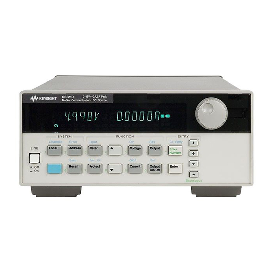
Quick Reference The Front Panel - At a Glance 14-character display Annunciators indicate Rotary control sets voltage, shows output measurements operating modes and status current, and menu parameters. Æ Ç and programmed values. conditions. to set the resolution; then adjust the value with the knob. -
Page 16: The Rear Panel - At A Glance
INH/FLT (remote Connector plug is interface connector. display connector. INHibit / internal FauLT) removable. RS-232 interface for connector. Connector plug Agilent 66111A, is removable. 66311B/D only. WARNING: NO OPERATOR SERVICEABLE PARTS REFER SERVICING TO SERVICE TRAINED OUTPUT 2 OUTPUT 1 0 - 12V / 0 - 1.5A... -
Page 17: Front Panel Number Entry
Quick Reference - 1 Front Panel Number Entry Enter numbers from the front panel using one the following methods: Use the arrow keys and knob to change voltage or current settings NOTE: The output must be ON to see the displayed values change in Meter mode. With the output enabled, this method changes the output voltage or current immediately. -
Page 18: Front Panel Annunciators
1 - Quick Reference Front Panel Annunciators Output 1 or output 2 is operating in constant voltage mode. Output 1 or output 2 is operating in constant current mode. Output 1 or output 2 is unregulated. The output is OFF. Press the Output On/Off key to turn the output on. The over-current protection state is ON. -
Page 19: Front Panel Menus - At A Glance
Accesses calibration menu (See Appendix B). Shift É È to select parameters (table shows factory defaults). to exit any menu. Meter Not valid for Agilent Model 66309B Not valid for Agilent Model 66111A Only valid for Agilent Model 66309B/D Only valid for Agilent Model 66311D/66309D... -
Page 20: Scpi Programming Commands - At A Glance
:PROTection :CLEar :SEQuence2 :DEFine ACQuire :DELay <n> :RELay :MODE DD | HD | DH | HH Not valid for Agilent 66111A :RI :MODE LATCHing | LIVE | OFF Only valid for Agilent 66309B/D :TYPE [:CAPacitance] HIGH | H2 | LOW... -
Page 21: General Information
General Information Document Orientation This manual describes the operation of the Agilent Model 66111A Fast Transient, the Agilent Model 66311B/D Mobile Communications, and the Agilent Model 66309B/D Dual Output DC Source. Agilent Models 66311D and 66309D have an additional DVM measurement input on the rear panel. Unless otherwise noted, these models will be referred to by the description "dc source"... -
Page 22: Safety Considerations
2 - General Information Safety Considerations This dc source is a Safety Class 1 instrument, which means it has a protective earth terminal. That terminal must be connected to earth ground through a power source equipped with a ground receptacle. Refer to the Safety Summary page at the beginning of this guide for general safety information. -
Page 23: Description And Model Differences
General Information - 2 Description and Model Differences The Agilent 66111A Fast Transient DC Source is a high performance dc power source that provides peak current sourcing and rapid, basic measurements in a compact, half-rack box. It is designed to simplify the testing of digital wireless communications products. -
Page 24: Common Capabilities
Enter language setting is saved in non-volatile memory. The dc source may be remotely programmed via the GPIB bus, and on Agilent 66111A and 66311B/D units, from an RS-232 serial port. GPIB programming is with SCPI commands (Standard Commands for Programmable Instruments), which make dc source programs compatible with those of other GPIB instruments. -
Page 25: Output 1 Characteristic
General Information - 2 Output 1 Characteristic The dc source’s main output (output 1) characteristic is shown in the following figure. The main output of the dc source may be adjusted to any value within the boundaries shown. Output Voltage ISET -1.2A VSET... -
Page 26: Output 2 Characteristic
2 - General Information Figure 2-1 also shows a single range − two quadrant capability. This means that the dc source is capable of sourcing as well as sinking current over the output voltage range from zero volts to the rated voltage. This negative current sinking capability provides fast downprogramming of the output of the dc source. -
Page 27: Option 521 Description (Agilent 66309B/D Only)
General Information - 2 Option 521 Description (Agilent 66309B/D only) Option 521 consists of the following enhancements to the output capabilities of Agilent models 66309B/66309D: ♦ Solid-state relays to connect and disconnect the output of the dc source. The relays are available on the output and sense terminals of outputs 1 and 2. When the solid state relays are open, the output impedance is effectively raised to about 500k ohms for output 1, and about 200k ohms for output 2. -
Page 29: Installation
Installation Installation and Operation Checklist Check the Output Compensation Check that the output compensation of the dc source is appropriate for your application. Refer to “Output Compensation” in this chapter. High mode provides the best transient response and can be used with phones having input capacitances from 5 to 12000µF. -
Page 30: Inspection
3 - Installation Inspection Damage When you receive your dc source, inspect it for any obvious damage that may have occurred during shipment. If there is damage, notify the shipping carrier and the nearest Agilent Sales and Support Office immediately. The list of Agilent Sales and Support Offices is at the back of this guide. Warranty information is printed in the front of this guide. -
Page 31: Bench Operation
Installation - 3 NOTE: This dc source generates magnetic fields that may affect the operation of other instruments. If your instrument is susceptible to operating magnetic fields, do not locate it in the immediate vicinity of the dc source. Typically, at three inches from the dc source, the electromagnetic field is less than 5 gauss. -
Page 32: Output Connections
3 - Installation Output Connections Turn the unit off before connecting any wires. Output 1 The main output connector (output 1) has a termination for the + and − output, the + and − sense terminals, and an earth ground terminal. The 5-pin connector is removable and accepts wires sizes from AWG 22 to AWG 12. -
Page 33: Remote Sense Connections
Installation - 3 The maximum allowable value of load lead resistance is 4 ohms total (2 ohms per side). This may be further limited to a lower value, based on peak current loading, by the maximum allowable dc voltage drop of 8 volts total (4 volts per side) as specified for remote sense operation. To illustrate, for up to 2 amps peak, the maximum allowable resistance is 4 ohms total, resulting in a maximum voltage drop of up to 8 volts. - Page 34 3 - Installation The sense leads are part of the dc source’s feedback path and must be kept at a low resistance (less than several ohms) to maintain optimal performance. Connect the sense leads carefully so that they do not become open-circuited.
-
Page 35: Load Regulation And Voltage Drop In The Remote Sense Leads
Installation - 3 OUTPUT 1/OUTPUT 2 CONNECTOR TWIST LEADS LENGTH MUST BE UNDER 20 INCHES TWIST PAIR LOAD WIRE RESISTANCE FIXTURE CONNECTIONS Figure 3-4. Remote Sense Connections with Test Fixture Load Regulation and Voltage Drop in the Remote Sense Leads The sense leads are part of the dc source’s feedback path and must be kept at a low resistance to maintain optimal performance. -
Page 36: Open Sense Lead Protection
3 - Installation Open Sense Lead Protection The main output (output 1) of the dc source has built-in open sense protection circuitry that detects if there is an open in either the positive or the negative remote sense lead or load lead path. For battery powered devices, undetected open sense connections can cause incorrect battery charger calibration, incorrect test results due to erroneous voltage settings, and low voltage phone shutdown due to a large transient voltage drop. -
Page 37: Local Sensing
Installation - 3 If the open sense lead protection circuit detects an open sense lead, the Prot annunciator on the front panel turns on and the output turns off. Bit 5 in the Questionable Status Registers is also set (see chapter 7 under "Programming the Status Registers"). -
Page 38: Output Compensation
3 - Installation Output Compensation High bandwidth performance and stability are achieved by using a software-switchable output compensation circuit. This compensation circuit has two bandwidth positions to optimize the response for two different ranges of phone capacitance. The compensation function is set using either the front panel TYPE:CAP command located in the Output menu (see chapter 5), or the OUTput:TYPE[:CAPacitance] SCPI command as explained in chapter 8. -
Page 39: Ovp Considerations
Installation - 3 OVP Considerations CAUTION: Disabling the OVP protection circuit may cause excessive output voltages, such as can occur if the remote sense leads are shorted, to damage the equipment under test. The dc source is shipped from the factory with its overvoltage protection circuit enabled. You can disable the OVP circuit using either the front panel VOLT PROT command located in the OV menu, or the VOLTage:PROTection:STATe SCPI command as explained in chapter 8. -
Page 40: Measuring Circuits That Are Not Powered By The Main Output
3 - Installation NOTE: The DVM is not designed to measure voltages that are greater than +25 Vdc or less than −4.5 Vdc with respect to the negative terminal of the main output. The following sections discuss restrictions that apply when using the DVM to measure voltages on circuits that are not powered by the main output, or that are floating with respect to the main output. -
Page 41: Measuring Circuits That Are Floating With Respect To The Main Output
Installation - 3 ♦ You cannot measure voltages greater than +25 Vdc with respect to the negative terminal of the main output. A situation where this could occur is illustrated by R1 in figure 3-8, which has only a 12 Vdc drop across it but is 36 Vdc + Vlead with respect to the negative terminal of the main output. -
Page 42: External Protection Connections
3 - Installation External Protection Connections This rear panel connector, has a fault output port and an inhibit input port. The fault (FLT) output, also referred to as the DFI (discrete fault indicator) signal in the front panel and SCPI commands, is an open collector circuit that pulls the positive output low with respect to the negative (chassis-referenced) common. -
Page 43: Digital I/O Connections
Figure 3- . Digital I/O Examples Computer Connections The dc source can be controlled through an GPIB interface. Agilent 66111A and 66311B/D units can also be controlled through an RS-232 interface. GPIB Interface Follow the GPIB card manufacturer’s directions for card installation and software driver setup. -
Page 44: Rs-232 Interface
Make sure all connectors are fully seated and the lock screws are firmly finger-tightened. RS-232 Interface Agilent 66111A and 66311B/D dc sources have an RS-232 programming interface, which is activated by commands located in the front panel menu. All applicable SCPI and COMPatibility commands Address are available through RS-232 programming. -
Page 45: Turn-On Checkout
Turn-On Checkout Checkout Procedure Successful tests in this chapter provide a high degree of confidence that your unit is operating properly. For verification tests, see appendix B. Complete performance tests are given in the Service Guide. NOTE: To perform the checkout procedure, you will need a wire for shorting the output terminals together. - Page 46 4 - Turn-On Checkout Procedure Display Explanation Plug the output connector Restores the output sense connections. The Prot back into the unit. annunciator is still on. Press Shift, Prot Clear NO FAULT Clears the protection condition. Prot is off; CV is on. Press Voltage VOLT 0.000 Display shows the output voltage setting of the unit.
-
Page 47: In Case Of Trouble
Turn-On Checkout - 4 Only perform steps 23 to 33 if you are verifying an Agilent 66309B or 66309D unit. Procedure Display Explanation Shift Channel toggles between channel 1 and channel Turn the unit on. Wait for 0.025V 0.0002A selftest to complete and 2. -
Page 48: Runtime Error Messages
4 - Turn-On Checkout Table 4-1. Power-On Selftest Errors Error No. Failed Test Error 0 No error Error 1 Non-volatile RAM RD0 section checksum failed Error 2 Non-volatile RAM CONFIG section checksum failed Error 3 Non-volatile RAM CAL section checksum failed Error 4 Non-volatile RAM STATE section checksum failed Error 5... -
Page 49: Front Panel Operation
Front panel Operation Introduction Here is what you will find in this chapter: ♦ a complete description of the front panel controls ♦ front panel programming examples NOTE: The dc source must be in set to Local mode to use the front panel controls. Press the key on the front panel to put the unit in local mode. - Page 50 5 – Front Panel Operation 14-character vacuum fluorescent display for showing output measurements and Display programmed values. Annunciators light to indicate operating modes and status conditions: Annunciators CV The dc source output is in constant-voltage mode. CC The dc source output is in constant-current mode. Unr The dc source output is in an unregulated state.
-
Page 51: System Keys
Front Panel Operation - 5 System Keys Refer to the examples later in this chapter for more details on the use of these keys. SYSTEM Channel Error Local Address Save Recall Figure 5-2. System Keys This is the blue, unlabeled key, which is also shown as Shift in this guide. -
Page 52: Function Keys
5 – Front Panel Operation Function Keys Refer to the examples later in this chapter for more details on the use of these keys. FUNCTION Input Meter Voltage Output Prot Cir Current Protect Output On/Off Figure 5-3. Function Keys Immediate Action Keys Immediate action keys immediately execute their corresponding function when pressed. -
Page 53: Metering Keys
Sets the # of points in front panel measurement buffer ( 1, 2, 4, 8, 16, 32, 64, 128, 256, 512, 1024, 2048) Notes: not valid for Agilent 66111A only valid for Agilent 66311D/66309D reading = the returned measurement value = a numeric value char = a character string parameter to scroll through the menu commands. -
Page 54: Output Control Keys
5 – Front Panel Operation Output Control Keys Output control keys control the output functions of the dc source. Voltage Press this key to access the voltage menu. Display Command Function VOLT <value> Sets the voltage of output 1 (the main output of all models) VOLT <value>... -
Page 55: Entry Keys
Front Panel Operation - 5 Entry Keys Refer to the examples later in this chapter for more details on the use of these keys. ENTRY Cir Entry Enter Number Enter Backspace Figure 5-4. Entry Keys È É These keys let you scroll through choices in a parameter list that apply to a specific command. -
Page 56: Examples Of Front Panel Programming
5 – Front Panel Operation Examples of Front Panel Programming You will find these examples on the following pages: Using the front panel display Setting the output voltage, current, and compensation Setting the output 2 voltage and current Querying and clearing output protection Making basic front panel measurements Making enhanced front panel measurements Making DVM measurements... -
Page 57: Setting The Output Voltage, Current, Compensation, And Relay Mode
Front Panel Operation - 5 2 - Setting the Output Voltage, Current, Compensation, and Relay Mode This example shows you how to set the output voltage and current. It also shows you how to set the compensation circuit for either high or low capacitance cellular phones. Relay mode only applies to Agilent models 66309B/D units that have Option 521 installed. -
Page 58: Setting The Output 2 Voltage And Current (Agilent 66309B/D Only)
5 – Front Panel Operation Setting the relay mode (Agilent 66309B/D with Option 521 only) Action Display Use Output ON/OFF to make sure that the output of the selected channel is off. The output must be turned off before any relay settings take effect. If the Dis annunciator is lit, the output is off. -
Page 59: Querying And Clearing Output Protection And Errors
Front Panel Operation - 5 To make minor changes to an existing value: On the Function keypad, press Current. CURR 0.500 On the Entry keypad, press Æ or Ç to select the digit in the numeric field that you wish to change. -
Page 60: Making Basic Front Panel Measurements
5 – Front Panel Operation 5 – Making Basic Front Panel Measurements As shipped from the factory, front panel measurements for the main output (output 1) are calculated from a total of 2048 readings taken at a 46.8 microsecond sampling rate. The unit alternates between voltage and current measurements. -
Page 61: Making Enhanced Front Panel Measurements
Figure 5-5. Default Front Panel Measurement Parameters All models except the Agilent 66111A have two current measurement ranges that can be selected in the Input menu. A high current range is available for measuring output currents of up to 7 amperes. A low current range is available for improved resolution when measuring output currents below 20 milliamperes. -
Page 62: Making Dvm Measurements (Agilent 66311D/66309D Only)
5 – Front Panel Operation To change the front panel time interval and buffer size for output waveform TINT 0.002 measurements, press Shift, Input. Then press q until you obtain the TINT command. Use the Entry keys to enter a value from 15.6 microseconds to 1 second in seconds. -
Page 63: Programming External Protection And The Digital Port Functions
Front Panel Operation - 5 8 - Programming External Protection and the Digital Port Functions Your dc source is shipped with the output port function set to RIDFI mode. In this mode the port functions as a remote inhibit input with a discrete fault indicator output signal. You can also configure the port to act as a Digital Input/Output device. -
Page 64: 10 - Storing And Recalling Instrument States
5 – Front Panel Operation Set the Language as follows: (not valid for Agilent 66309B/D) Action Display On the System keypad, press Address. ADDRESS 5 Scroll through the Address menu by pressing q. The LANG command lets you LANG:SCPI access the programming language. The È... -
Page 65: Introduction To Programming
Introduction to Programming External References GPIB References The most important GPIB documents are your controller programming manuals - BASIC, GPIB Command Library for MS DOS, etc. Refer to these for all non-SCPI commands (for example: Local Lockout). The following are two formal documents concerning the GPIB interface: ♦... -
Page 66: Vxiplug&Play Power Products Instrument Drivers
VXIplug&play instrument drivers for Microsoft Windows 95 and Windows NT are now available on the Web at http://www.agilent.com/find/drivers. These instrument drivers provide a high-level programming interface to your Agilent Technologies instrument. VXIplug&play instrument drivers are an alternative to programming your instrument with SCPI command strings. Because the instrument driver’s function calls work together on top of the VISA I/O library, a single instrument driver can be... -
Page 67: Accessing Online Help
Enter a value to set the GPIB Address RS-232 Capabilities of the DC Source Agilent 66111A and 66311B/D dc sources provide an RS-232 programming interface, which is activated by commands located under the front panel Address key. All SCPI and COMPatibility commands are available through RS-232 programming. -
Page 68: Rs-232 Flow Control
6 - Introduction to Programming SPACE Seven data bits with space parity (parity is always false) NONE Eight data bits without parity Parity options are stored in non-volatile memory. Baud Rate The front panel Address key lets you select one of the following baud rates, which is stored in non- volatile memory: 1200 2400... -
Page 69: Conventions Used In This Guide
Introduction to Programming - 6 Conventions Used in This Guide Angle brackets < > Items within angle brackets are parameter abbreviations. For example, <NR1> indicates a specific form of numerical data. Vertical bar Vertical bars separate alternative parameters. For example, NORM | TEXT indicates that either "TEXT"... -
Page 70: Multiple Commands In A Message
6 - Introduction to Programming Multiple Commands in a Message Multiple SCPI commands can be combined and sent as a single message with one message terminator. There are two important considerations when sending several commands within a single message: ♦ Use a semicolon to separate commands within a message. ♦... -
Page 71: Using Queries
Introduction to Programming - 6 Using Queries Observe the following precautions with queries: ♦ Set up the proper number of variables for the returned data. ♦ Read back all the results of a query before sending another command to the dc source. Otherwise a Query Interrupted error will occur and the unreturned data will be lost. -
Page 72: Query Indicator
6 - Introduction to Programming Query Indicator Following a header with a question mark turns it into a query (VOLTage?, VOLTage:PROTection?). If a query contains a parameter, place the query indicator at the end of the last header. VOLTage:PROTection? MAX Message Unit Separator When two or more message units are combined into a compound message, separate the units with a semicolon. -
Page 73: Suffixes And Multipliers
Introduction to Programming - 6 Suffixes and Multipliers Class Suffix Unit Unit with Multiplier Current ampere MA (milliampere) Amplitude volt MV (millivolt) Time second MS (millisecond) Common Multipliers kilo 1E-3 milli 1E-6 micro Response Data Types Character strings returned by query statements may take either of the following forms, depending on the length of the returned string: <CRD>... -
Page 74: Using Device Clear
The following statement shows how to send a device clear over the GPIB interface using the GPIB command library for C or QuickBASIC: IOCLEAR (705) SCPI Conformance Information SCPI Conformed Commands The Agilent 66111A, 66311B/D, and 66309B/D conform to SCPI Version 1995.0. ABOR OUTP:PROT:DEL STAT:QUES:ENAB CAL:DATA... -
Page 75: Programming The Dc Source
Programming the DC Source Introduction This chapter contains examples on how to program your dc source. Simple examples show you how to program: u output functions such as voltage and current u internal and external triggers u measurement functions u the status and protection functions NOTE: The examples in this chapter show which commands are used to perform a particular function, but do not show the commands being used in any particular programming... -
Page 76: Output Voltage
7 - Programming the DC Source Output Voltage The output voltage is controlled with the VOLTage command. To set the output voltage to 5 volts, use: VOLT for models that have a second output VOLT2 5 Maximum Voltage The maximum output voltage that can be programmed can be queried with: VOLT? MAX Overvoltage Protection The dc source can be programmed to turn off its output if the output voltage exceeds a preset peak... -
Page 77: Triggering Output Changes
Programming the DC Source - 7 Triggering Output Changes The dc source has two independent trigger systems. One is used for synchronizing output changes, and the other is used for synchronizing measurements. This section describes the output trigger system. The measurement trigger system is described under "Triggering Measurements". -
Page 78: Enabling The Output Trigger System
7 - Programming the DC Source Enabling the Output Trigger System When the dc source is turned on, the trigger subsystem is in the idle state. In this state, the trigger subsystem is disabled, ignoring all triggers. Sending the following commands at any time returns the trigger system to the idle state: ABOR *RST... -
Page 79: Making Basic Measurements
Programming the DC Source - 7 Making Basic Measurements All dc sources have excellent output voltage and current measurement capability. NOTE: There is only one measurement system in the dc source. Therefore, you can perform only one measurement function (voltage, current, or DVM) at a time. All measurements are performed by digitizing the instantaneous output voltage or current for a defined number of samples and sample interval, storing the results in a buffer, and then calculating the measured result. -
Page 80: Window Functions
7 - Programming the DC Source When the instrument is turned on and at *RST, the output voltage or current sampling rate is 15.6 microseconds, and the sweep size is set to 2048 data points. This means that it takes about 32 milliseconds to fill up 2048 data points in the data buffer. -
Page 81: Current Ranges And Measurement Detector
Programming the DC Source - 7 There are two ways to make enhanced measurements: ♦ Use the MEASure queries to immediately start acquiring new voltage or current data, and return measurement calculations from this data as soon as the buffer is full. This is the easiest way to make measurements, since it requires no explicit trigger programming. -
Page 82: Pulse Measurements
7 - Programming the DC Source Pulse Measurements After pulse data has been acquired, use FETCh queries to return measurement data in the shortest time. FETCh queries do not trigger the acquisition of new measurement data, but return different calculations from the data that was acquired. -
Page 83: Returning All Measurement Data From The Data Buffer
Programming the DC Source - 7 Returning All Measurement Data From the Data Buffer The MEASure:ARRay and FETCh:ARRay queries return all data values of the instantaneous voltage or current buffer. No weighting function is applied, returning only raw data from the buffer. The commands are: MEAS:ARR:CURR? MEAS:ARR:VOLT? -
Page 84: Triggered Measurements
7 - Programming the DC Source Triggered Measurements Use the measurement trigger system to synchronize the acquisition of measurements with either a BUS or internal trigger. You can trigger voltage and current measurements on the main output (output 1) and on the DVM. -
Page 85: Enabling The Measurement Trigger System
Programming the DC Source - 7 Enabling the Measurement Trigger System When the dc source is turned on, the trigger system is in the idle state. In this state, the trigger system is disabled and it ignores all triggers. Sending the following commands at any time returns the trigger system to the idle state: ABORt *RST... -
Page 86: Generating Measurement Triggers
7 - Programming the DC Source Generating Measurement Triggers Single Triggers After you specify the appropriate trigger source and sensing function, generate triggers as follows: GPIB Triggers Send one of the following commands over the GPIB: TRIG:IMM (not affected by the trigger source setting) *TRG an IEEE-488 Group Execute Trigger bus command To trigger off of the output signal, you must specify the output level that... - Page 87 Programming the DC Source - 7 One way to wait for results without tying up the computer is to use the SCPI command completion commands. For example, you can send the *OPC command after INITialize, then occasionally poll the OPC status bit in the standard event status register for status completion while doing other tasks. You can also set up an SRQ condition on the OPC status bit going true and do other tasks until the SRQ interrupts.
-
Page 88: Pre-Trigger And Post-Trigger Data Acquisition
7 - Programming the DC Source Pre-trigger and Post-trigger Data Acquisition The measurement system lets you capture data before, after, or at the trigger signal. When a measurement is initiated, the dc source continuously samples the instantaneous signal level of the sensing function. As shown in figure 7-7, you can move the block of data being read into the acquisition buffer with reference to the acquisition trigger. -
Page 89: Power-On Conditions
Programming the DC Source - 7 Power-On Conditions Refer to the *RST command description in chapter 8 for the power-on conditions of the status registers. QUESTIONABLE STATUS CONDITION PTR/NTR EVENT ENABLE N.U. N.U. LOGICAL UNR2 1024 1024 1024 1024 OUTPut:DFI N.U. -
Page 90: Operation Status Group
7 - Programming the DC Source Table 7-1. Bit Configurations of Status Registers Signal Meaning Operation Status Group The dc source is computing new calibration constants The dc source is waiting for a trigger The dc source is in constant voltage mode Output 2 is operating in constant voltage mode The dc source is in constant current mode The dc source is in negative constant current mode... -
Page 91: Questionable Status Group
Programming the DC Source - 7 Questionable Status Group The Questionable Status registers record signals that indicate abnormal operation of the dc source. As shown in figure 7-7, the group consists of the same type of registers as the Status Operation group. The outputs of the Questionable Status group are logically-ORed into the QUEStionable summary bit (3) of the Status Byte register. -
Page 92: Determining The Cause Of A Service Interrupt
7 - Programming the DC Source The MSS Bit This is a real-time (unlatched) summary of all Status Byte register bits that are enabled by the Service Request Enable register. MSS is set whenever the dc source has one or more reasons for requesting service. -
Page 93: Monitoring Both Phases Of A Status Transition
Programming the DC Source - 7 Step 1 Program the Operation Status PTR register to allow a positive transition at bit 10 to be latched into the Operation Status Event register, and allow the latched event to be summed into the Operation summary bit. Use: STAT:OPER:PTR 1024;ENAB 1024 Step 2 Program the Questionable Status PTR register to allow a positive transition at bits 0,... -
Page 94: Discrete Fault Indicator (Dfi)
7 - Programming the DC Source Discrete Fault Indicator (DFI) The discrete fault indicator is an open-collector logic signal connected to the rear panel FLT connection that can be used to signal external devices when a fault condition is detected. To select the internal fault source that drives this signal, use: OUTPut:DFI:SOURce QUEStionable | OPERation | ESB | RQS | OFF To enable or disable the DFI output, use:... -
Page 95: Language Dictionary
Language Dictionary Introduction This section gives the syntax and parameters for all the IEEE 488.2 SCPI commands and the Common commands used by the dc source. It is assumed that you are familiar with the material in chapter 6, which explains the terms, symbols, and syntactical structures used here and gives an introduction to programming. - Page 96 8 – Language Dictionary Table 8-1. Subsystem Commands Syntax ABORt Resets the trigger system to the Idle state CALibrate :CURRent [:SOURce] [:DC] [:POSitive] Calibrate positive output current and high current measurement range :MEASure [:DC] :LOWRange Calibrate low current measurement range Calibrate ac current measurement circuits :CURRent2 Calibrate output2 current...
- Page 97 Language Dictionary - 8 Table 8-1. Subsystem Commands Syntax (continued) :DVM [:DC]? Returns DVM dc voltage measurement Returns DVM rms voltage measurement :ACDC? :VOLTage [:DC]? Returns dc voltage Returns the total rms voltage (ac+dc) :ACDC? :HIGH? Returns the HIGH level of a voltage pulse :LOW? Returns the LOW level of a voltage pulse :MAX?
- Page 98 8 – Language Dictionary Table 8-1. Subsystem Commands Syntax (continued) :PROTection [:LEVel] <n> Sets the overvoltage protection threshold :STATe <bool> Enables/disables overvoltage protection VOLTage2 [:LEVel] Sets the output2 voltage level [:IMMediate][:AMPLitude] <n> :TRIGgered [:AMPLitude] <n> Sets the triggered output2 voltage level STATus Presets all enable and transition registers to power-on :PRESet...
-
Page 99: Common Commands
[SOUR:]VOLT:PROT[:LEV] MAX 22 V *RST OVP Value OUTP:PROT:DEL MAX 2,147,483.647 *RST Protection Delay Value 0.08 seconds Low range = 0 − 20 mA (not valid for Agilent SENS:CURR:RANG High Range = 20 mA − MAX 66111A) *RST Current Range Value MAX... -
Page 100: Calibration Commands
8 – Language Dictionary Calibration Commands Calibration commands let you enable and disable the calibration mode, change the calibration password, calibrate current and voltage programming, and store new calibration constants in nonvolatile memory. NOTE: If calibration mode has not been enabled with CALibrate:STATe, programming the calibration commands will generate an error. -
Page 101: Calibrate:data
Language Dictionary - 8 CALibrate:DATA This command enters a calibration value that you obtain by reading an external meter. You must first select a calibration level (with CALibrate:LEVel) for the value being entered. Command Syntax CALibrate:DATA<NRf> Parameters <external reading> Unit A (amperes) Examples CAL:DATA 3222.3 MA CAL:DATA 5.000 Related Commands CAL:STAT... -
Page 102: Calibrate:save
8 – Language Dictionary CALibrate:SAVE This command saves any new calibration constants after a calibration procedure has been completed in nonvolatile memory. If CALibrate:STATe OFF is programmed without a CALibrate:SAVE, the previous calibration constants are restored.. Command Syntax CALibrate:SAVE Parameters None Examples CAL:SAVE Related Commands CAL:PASS CAL:STAT... -
Page 103: Display Commands
Language Dictionary - 8 Display Commands Display commands control the front panel display of the dc source. Annunciators are not affected. DISPlay This command turns the front panel display on or off. When off, the front panel display is blank. Command Syntax DISPlay[:WINDow][:STATe] <bool>... -
Page 104: Measurement Commands
8 – Language Dictionary Measurement Commands Measurement commands consist of format, measure, and sense commands. Format commands specify the data formatting of all array queries. You can specify the data type, type length, and byte order. Measure commands measure the output voltage or current. Measurements are performed by digitizing the instantaneous output voltage or current for a specified number of samples, storing the results in a buffer, and calculating the measured result. -
Page 105: Format:border
Language Dictionary - 8 FORMat:BORDer This command selects whether the binary data is transferred in normal or swapped byte order. When NORMal is selected, the first byte sent is the sign bit and seven most significant bits of the exponent, and the last byte sent is the least significant byte of the mantissa. -
Page 106: Measure:current? Fetch:current
8 – Language Dictionary MEASure:CURRent? FETCh:CURRent? These queries return the dc output current. Query Syntax MEASure[:SCALar]:CURRent[:DC]? FETCh[:SCALar]:CURRent[:DC]? Parameters None Examples MEAS:CURR? FETC:CURR:DC? Returned Parameters <NR3> Related Commands MEAS:VOLT? MEASure:CURRent2? Agilent 66309B/D only This query measures the output current at the auxiliary output. Output 2 measurements are calculated from a total of 2048 readings taken at a 15.6 microsecond sampling rate. -
Page 107: Measure:current:high? Fetch:current:high
Language Dictionary - 8 MEASure:CURRent:HIGH? FETCh:CURRent:HIGH? Agilent 66311B/D, 66309B/D only These queries return the High level current of a current pulse waveform. The instrument first measures the minimum and maximum data points of the pulse waveform. It then generates a histogram of the pulse waveform using 16 bins between the maximum and minimum data points. -
Page 108: Measure:current:minimum? Fetch:current:minimum
8 – Language Dictionary MEASure:CURRent:MINimum? FETCh:CURRent:MINimum? Agilent 66311B/D, 66309B/D only These queries return the minimum output current. Query Syntax MEASure[:SCALar]:CURRent:MINimum? FETCh[:SCALar]:CURRent:MINimum? Parameters None Examples MEAS:CURR:MIN? FETC:CURR:MIN? Returned Parameters <NR3> Related Commands MEAS:CURR:MAX? MEASure:DVM? FETCh:DVM? Agilent 66311D/66309D only These queries measure dc voltage. Query Syntax MEASure[:SCALar]:DVM[:DC]? FETCh[:SCALar]:DVM[:DC]? Parameters None... -
Page 109: Measure:voltage2
Language Dictionary - 8 MEASure:VOLTage2 Agilent 66309B/D only This query measures the output voltage at the auxiliary output. Output 2 measurements are calculated from a total of 2048 readings taken at a 15.6 microsecond sampling rate. These parameters are fixed. Query Syntax MEASure[:SCALar]:VOLTage2[:DC]? Parameters None Examples MEAS:VOLT2? -
Page 110: Measure:voltage:low? Fetch:voltage:low
8 – Language Dictionary MEASure:VOLTage:LOW? FETCh:VOLTage:LOW? Agilent 66311B/D, 66309B/D only These queries return the Low level voltage of a voltage pulse waveform. The instrument first measures the minimum and maximum data points of the pulse waveform. It then generates a histogram of the pulse waveform using 16 bins between the maximum and minimum data points. -
Page 111: Sense:current:detector
Language Dictionary - 8 SENSe:CURRent:DETector Agilent 66311B/D, 66309B/D only This command lets you select the type of detector used for output current measurements. Two choices for detecting current measurements are available: This is the preferred choice for all dynamic current measurements. When ACDC is selected, ACDC the measured output current includes the current that flows in the instrument’s output capacitor. -
Page 112: Sense:function
8 – Language Dictionary SENSe:FUNCtion This command configures the sensing function for triggered measurements. The dc source has up to three measurement sensors as described below. The query returns the function setting. Senses the current measurement at the main output (output 1) CURRent Senses the voltage measurement at the DVM inputs (Agilent 66311D/66309D only) -
Page 113: Sense:sweep:tinterval
Language Dictionary - 8 SENSe:SWEep:TINTerval This command defines the time period between samples. The value that you enter for the time interval will be rounded to the nearest 15.6 microsecond increment. Command Syntax SENSe:SWEep:TINTerval<NRf+> Parameters 15.6 microseconds through 31200 seconds *RST Value 15.6 microseconds Examples SENS:SWE:TINT 31.2E-6 Query Syntax SENSe:SWEep:TINTerval? -
Page 114: Output Commands
8 – Language Dictionary Output Commands Output commands consist of instrument, output and source commands. Instrument commands control the output coupling on Agilent 66309B/D units. Output commands control the output and digital port functions. Source commands program the actual voltage, current, and digital port output. INSTrument:COUPle:OUTPut:STATe Agilent 66309B/D units with firmware revision A.02.04 and up only Couples Output 1 and Output 2. -
Page 115: Output:dfi
Language Dictionary - 8 Command Syntax OUTPut[1|2]:RELay:MODE <mode> Parameters DD | DH | HD | HH (sets output 1 relay mode DH) Examples OUTP:REL:MODE DH OUTP2:REL:MODE HH (sets output 2 relay mode HH) Query Syntax OUTPut[1|2]:REL:MODE? Returned Parameters <CRD> CAUTION: Non-volatile memory has a finite maximum number of write cycles. -
Page 116: Output:protection:clear
8 – Language Dictionary OUTPut:PROTection:CLEar This command clears the latch that disables the output when an overvoltage, overcurrent, overtemperature, or remote inhibit status condition is detected. All conditions that generate the fault must be removed before the latch can be cleared. The output is then restored to the state it was in before the fault condition occurred. -
Page 117: [Source:]Current
Language Dictionary - 8 The dc source is shipped with the output compensation set LOW mode, which provides stable operation for all types of phones. The HIGH mode setting provides better transient response performance for phones that have input capacitances greater than 5 µF. In High mode, operation of the dc source will be unstable when connected to phones that have input capacitances less than 5 µF. -
Page 118: [Source:]Current:protection:state
8 – Language Dictionary [SOURce:]CURRent:PROTection:STATe This command enables or disables the overcurrent protection (OCP) function on all output channels. If the dc source overcurrent protection function is enabled and the dc source goes into constant current operation, then the output is disabled and the Questionable Condition status register OC bit is set (see chapter 7 about programming the status registers). -
Page 119: [Source:]Digital:data
Language Dictionary - 8 [SOURce:]DIGital:DATA This command programs the digital control port when the port is configured for Digital I/O operation. The port has three signal pins and a digital ground pin. Pins 1 and 2 are output pins controlled by bits 0 and 1. -
Page 120: [Source:]Voltage2
8 – Language Dictionary [SOURce:]VOLTage2 Agilent 66309B/D only This command sets the output voltage level of the auxiliary output. Command Syntax [SOURce:]VOLTage2[:LEVel][:IMMediate][:AMPLitude]<NRf+> Parameters see Table A-3 Default Suffix V (volts) *RST Value 0 Examples VOLT2 500mV !set output2 voltage to 0.5V Query Syntax [SOURce:]VOLTage2[:LEVel][:IMMediate][:AMPLitude]? Returned Parameters <NR3>... -
Page 121: [Source:]Voltage:trigger
Language Dictionary - 8 [SOURce:]VOLTage:TRIGger This command sets the pending triggered voltage level of the dc source. The pending triggered level is a stored voltage value that is transferred to the output terminals when a trigger occurs. In order for a trigger to occur, the trigger subsystem must be initiated (see the INITiate command in the trigger subsystem). -
Page 122: Status:operation
8 – Language Dictionary Table 8-4. Bit Configuration of Operation Status Registers Bit Position 15–13 Bit Name used used used Bit Weight 4096 2048 1024 CAL = The dc source is computing new calibration constants. WTG = The dc source is waiting for a trigger. CV = The dc source is operating in constant voltage mode. -
Page 123: Status:operation:ntr Status:operation:ptr
Language Dictionary - 8 STATus:OPERation:NTR STATus:OPERation:PTR These commands set or read the value of the Operation NTR (Negative-Transition) and PTR (Positive- Transition) registers. These registers serve as polarity filters between the Operation Enable and Operation Event registers to cause the following actions: u When a bit in the Operation NTR register is set to 1, then a 1-to-0 transition of the corresponding bit in the Operation Condition register causes that bit in the Operation Event register to be set. -
Page 124: Status:questionable:condition
8 – Language Dictionary STATus:QUEStionable:CONDition? This query returns the value of the Questionable Condition register. That is a read-only register, which holds the real-time (unlatched) questionable status of the dc source. Query Syntax STATus:QUEStionable:CONDition? Parameters None Examples STAT:QUES:COND? Returned Parameters <NR1> (register value) STATus:QUEStionable:ENABle This command and its query set and read the value of the Questionable Enable register. -
Page 125: System Commands
Language Dictionary - 8 System Commands System commands control system functions that are not directly related to output control or measurement functions. SYSTem:ERRor? This query returns the next error number followed by its corresponding error message string from the remote programming error queue. The queue is a FIFO (first-in, first-out) buffer that stores errors as they occur. -
Page 126: Trigger Commands
8 – Language Dictionary Trigger Commands Trigger commands consist of trigger and initiate commands. They are used to generate output transients and measurement triggers. Initiate commands initialize the trigger system. Trigger commands control the remote triggering of the dc source. Trigger commands (and Initate commands) are referenced either by name or by number. The correspondence between names and numbers is: Sequence Number Sequence Name... -
Page 127: Initiate:continuous:sequence1 Initiate:continuous:name Transient
Language Dictionary - 8 INITiate:CONTinuous:SEQuence1 INITiate:CONTinuous:NAME TRANsient These commands control the output transient trigger system. continuously initiates the output trigger system.. 1 or ON 0 or OFF turns off continuous triggering. In this state, the output trigger system must be initiated for each trigger using INITiate:SEQuence. -
Page 128: Trigger:sequence2 Trigger:acquire
8 – Language Dictionary TRIGger:SEQuence2 TRIGger:ACQuire These commands generate a BUS trigger for the measurement trigger system. When the measurement trigger system is enabled, the measurement trigger causes the dc source to measure either the voltage or current on the main output or the DVM inputs and store the results in a buffer. The SENSe:FUNCtion command selects the signal that will be measured. -
Page 129: Trigger:sequence2:Count:voltage Trigger:acquire:count:voltage
Language Dictionary - 8 TRIGger:SEQuence2:COUNt:VOLTage TRIGger:ACQuire:COUNt:VOLTage This command sets up a successive number of triggers for measuring voltage data. With this command, the trigger system needs to be initialized only once at the start of the acquisition period. After each completed measurement, the instrument waits for the next valid trigger condition to start another measurement. -
Page 130: Trigger:sequence2:Hysteresis:dvm Trigger:acquire:hysteresis:dvm
8 – Language Dictionary TRIGger:SEQuence2:HYSTeresis:DVM TRIGger:ACQuire:HYSTeresis:DVM Agilent 66311D/66309D only This command defines a band around the trigger level through which the input signal must pass before a DVM measurement can occur. The band limit above and below the trigger level is one half of the hysteresis value added to or subtracted from the trigger level. -
Page 131: Trigger:sequence2:Level:current Trigger:acquire:level:current
Language Dictionary - 8 TRIGger:SEQuence2:LEVel:CURRent TRIGger:ACQuire:LEVel:CURRent This command sets the trigger level for internally triggered current measurements. A positive current trigger occurs when the current level changes from a value less than the lower hysteresis band limit to a value greater than the upper hysteresis band limit. Similarly, a negative current trigger occurs when the current level changes from a value greater than the upper hysteresis band limit to a value less than the lower hysteresis band limit. -
Page 132: Trigger:sequence2:Level:voltage Trigger:acquire:level:voltage
8 – Language Dictionary TRIGger:SEQuence2:LEVel:VOLTage TRIGger:ACQuire:LEVel:VOLTage This command sets the trigger level for internally triggered voltage measurements. A positive voltage trigger occurs when the voltage level changes from a value less than the lower hysteresis band limit to a value greater than the upper hysteresis band limit. Similarly, a negative voltage trigger occurs when the voltage level changes from a value greater than the upper hysteresis band limit to a value less than the lower hysteresis band limit. -
Page 133: Trigger:sequence2:Slope:dvm Trigger:acquire:slope:dvm
Language Dictionary - 8 TRIGger:SEQuence2:SLOPe:DVM TRIGger:ACQuire:SLOPe:DVM Agilent 66311D/66309D only This command sets the slope of the DVM input signal. POSitive measurement triggering occurs on the rising edge. measurement triggering occurs on the falling edge. NEGative measurement triggering occurs on either edge. EITHer Command Syntax TRIGger:SEQuence2:SLOPe:DVM<slope>... -
Page 134: Trigger:sequence2:Source Trigger:acquire:source
8 – Language Dictionary TRIGger:SEQuence2:SOURce TRIGger:ACQuire:SOURce These commands select the trigger source for measurement triggers as follows: GPIB device, *TRG, or <GET> (Group Execute Trigger) trigger is generated internally when the measured waveform crosses the trigger level INTernal with the selected slope. Command Syntax TRIGger:SEQuence2:SOURce<source>... -
Page 135: Common Commands
Language Dictionary - 8 Common Commands *CLS This command causes the following actions (see chapter 7 for the descriptions of all registers): u Clears the Standard Event Status, Operation Status Event, and Questionable Status Event registers u Clears the Status Byte and the Error Queue u If *CLS immediately follows a program message terminator (<NL>), then the output queue and the MAV bit are also cleared. -
Page 136: Esr
This query requests the dc source to identify itself. It returns a string composed of four fields separated by commas. Query Syntax *IDN? Returned Parameters <AARD> Field Information Agilent Technologies Manufacturer xxxxxA model number followed by a letter suffix zero or the unit’s serial number if available <A>.xx.xx Revision levels of firmware. -
Page 137: Opt
Language Dictionary - 8 *OPT? This query requests the dc source to identify any options that are installed. Options are identified by number. A 0 indicates no options are installed. Query Syntax *OPT? Returned Parameters <AARD> *PSC This command controls the automatic clearing at power-on of the Service Request Enable and the Standard Event Status Enable registers. -
Page 138: Rst
8 – Language Dictionary *RST This command resets the dc source to a factory-defined state as defined in the following table. *RST also forces an ABORt command. Table 8-7. *RST Settings CAL:STAT [SOUR:]CURR2 10% of MAX* DIG:DATA [SOUR:]CURR2:TRIG 10% of MAX* DISP:STAT [SOUR:]CURR:PROT:STAT DISP:MODE... -
Page 139: Sre
Language Dictionary - 8 *SRE This command sets the condition of the Service Request Enable Register. This register determines which bits from the Status Byte Register (see *STB for its bit configuration) are allowed to set the Master Status Summary (MSS) bit and the Request for Service (RQS) summary bit. A 1 in any Service Request Enable Register bit position enables the corresponding Status Byte Register bit and all such enabled bits then are logically ORed to cause Bit 6 of the Status Byte Register to be set. -
Page 140: Trg
8 – Language Dictionary *TRG This common command generates a trigger when the trigger subsystem has BUS selected as its source. The command has the same affect as the Group Execute Trigger (<GET>) command. Command Syntax *TRG Parameters None Related Commands ABOR INIT TRIG[:IMM] <GET>... -
Page 141: Additional Commands
Language Dictionary - 8 Additional Commands The following commands are added to the language dictionary to provide limited Fluke PM2811 Power Supply compatibility. These comands will only work when the SYSTem LANGuage is set to SCPI. INSTrument:STATe This command enables or disables the dc source output. The state of a disabled output is a condition of zero output voltage and a model-dependent minimum source current (see *RST). -
Page 142: Current:protection:tripped
8 – Language Dictionary CURRent:PROTection:TRIPped? This query reports if the OCP (overcurrent protection) status bit is set. 0 = bit is not set; 1 = bit is set. Query Syntax [SOURce:]CURRent:PROTection:TRIPped? Returned Parameters <NR1> 0 or 1 Examples CURR:PROT:TRIP? Equivalent SCPI Command STATus:QUEStionable:CONDition? VOLTage:LIMit:HIGH? This query returns the maximum rated voltage of the instrument. -
Page 143: A - Specifications
0.05% +2.3mA when programming between zero and 0.03% of full scale current. Agilent 66111A units do not have a low current range, the dc measurement accuracy applies from 0 amperes to the rated current. Applies with current detector set to DC. ACDC mode accuracy is 0.2% + 3mA for sourcing and 0.2% + 3.6 mA for sinking. -
Page 144: Supplemental Characteristics
A - Specifications Supplemental Characteristics Table A-2 lists the supplemental characteristics, which are not warranted but are descriptions of typical performance determined either by design or type testing. Table A-2. Supplemental Characteristics Parameter Agilent 66111A Agilent Agilent 66311B/D, 66309B/D Agilent 66309B/D... - Page 145 May be reduced by changing the default conditions of 2048 data points but measurement uncertainty due to noise will increase. Compatibility language is used to program the Agilent 663xA Series power supplies. Not all Agilent 66111A/66311B capabilities are available when using the Compatibility language. Also, Compatibility language is not available for Agilent...
- Page 146 A - Specifications Table A-2. Supplemental Characteristics (continued) Parameter All Models Recommended Calibration from the date the unit is put into 1 year Interval service Regulatory Compliance Listing pending: UL 3111-1 Certified to: CSA 22.2 No. 1010.1 Conforms to: IEC 1010-1, EN 61010-1 Complies with: EMC directive 89/336/EEC (ISM Group1 Class B)
-
Page 147: Verification And Calibration
Verification and Calibration Introduction This appendix includes verification and calibration procedures for the Agilent 66111A Fast Transient DC Source, and the Agilent 66311B/D, 66309B/D Mobile Communications DC Sources. Instructions are given for performing the procedures either from the front panel or from a controller over the GPIB. -
Page 148: Performing The Verification Tests
B - Verification and Calibration NOTE: Connector NOTE: Connector is removable is removable Load Current DC ammeter DC voltmeter resistor monitor NOTE: Connector is removable External DC supply (connect only for verification) Load DC ammeter resistor 400 ohm DVM connector connect this lead only when calibrating the unit External... -
Page 149: Voltage Programming And Measurement Accuracy
Verification and Calibration - B Voltage Programming and Measurement Accuracy This test verifies the voltage programming, GPIB measurement, and front panel meter functions. Values read back over the GPIB should be the same as those displayed on the front panel. Measure the dc output voltage at the output terminals. - Page 150 B - Verification and Calibration Steps 7-11 apply to Agilent 66309B/D output 2 only Turn off the dc source and connect the DMM and current monitor to output 2 as shown in figure B-1A. Then turn on the dc source and select Output 2.
-
Page 151: Dvm Measurement Accuracy
Verification and Calibration - B DVM Measurement Accuracy This test verifies the DVM measurement accuracy. Connect all equipment as shown in figure B-1D. Action Normal Result Turn off the dc source and connect the external DMM and the external power supply to the DVM inputs as shown in figure B-1D. Connect only the negative output lead of output 1 to the DVM inputs. - Page 152 B - Verification and Calibration Table B-2. Verification Test Record for Agilent Model 66111A Model Agilent 66111A Report No.____________ Date_____________ Test Description Minimum Recorded Results Maximum Specification Specification Voltage Programming and Measurement −10 mV Low Voltage _____mV +10 mV Vlo −5 mV...
- Page 153 Verification and Calibration - B Table B-4. Verification Test Record for Agilent Model 66309B/D Model Agilent___________ Report No.____________ Date_____________ Test Description Minimum Recorded Results Maximum Specification Specification Voltage Programming and Measurement −10 mV Low Voltage _____mV +10 mV Vlo −5 mV Front Panel measurement Vfplo _____mV...
-
Page 154: Performing The Calibration Procedure
DATE <char> Displays the calibration date. (0 if none is supplied) CAL:PASS <value> Set new calibration password. not valid for Agilent 66111A Notes: value = a numeric value char = a character string parameter to scroll through the menu commands. -
Page 155: Front Panel Calibration Procedure
Verification and Calibration - B Front Panel Calibration Procedure These procedures assume you understand how to operate front panel keys (see chapter 5). Make sure the sense switch is set to Remote and the sense terminals are directly jumpered to the output terminals. Calibration procedures can only be performed with the dc source set to the SCPI programming language. - Page 156 B - Verification and Calibration Steps 11-16 apply to Agilent 66309B/D output 2 only Connect the external DMM (in voltage mode) directly to output 2. Do not connect the load resistor or current shunt. Select output 2. Press Shift Cal, scroll to CAL VOLT2, and press Enter. CAL:VOLT2 Press Shift Cal, scroll to CAL LEV, and press Enter to select the first CAL:LEV P1...
- Page 157 Verification and Calibration - B Steps 27-32 apply to Agilent 66309B/D output 2 only Connect the appropriate current monitor to output 2 as shown in figure B-1A. Connect the DMM (in voltage mode) across the current shunt. Select output 2. Press Shift Cal, scroll to CAL CURR2, and press Enter.
- Page 158 B - Verification and Calibration DVM Calibration (applies to Agilent 66311D, 66309D only) Action Display Connect the DVM inputs directly to output 1. Connect the external DMM to the DVM inputs as shown in figure B-1D. Do not connect the Agilent 3478 DMM.
-
Page 159: Calibration Error Messages
Verification and Calibration - B Calibration Error Messages Errors that can occur during calibration are shown in the following table. Table B-3. GPIB Calibration Error Messages Error Meaning CAL switch prevents calibration (This is a hardware disable, see the Service Manual.) CAL password is incorrect CAL not enabled Computed readback cal constants are incorrect... - Page 161 Error Messages Error Number List This appendix gives the error numbers and descriptions that are returned by the dc source. Error numbers are returned in two ways: ♦ Error numbers are displayed on the front panel ♦ Error numbers and messages are read back with the SYSTem:ERRor? query. SYSTem:ERRor? returns the error number into a variable and returns two parameters: an NR1 and a string.
-
Page 162: C - Error Messages
C – Error Messages Table C-1. Error Numbers (continued –131 Invalid suffix [unrecognized units, or units not appropriate] –138 Suffix not allowed –141 Invalid character data [bad character, or unrecognized] –144 Character data too long –148 Character data not allowed –150 String data error –151... - Page 163 Error Messages - C Table C-1. Error Numbers (continued Selftest Errors 0 through 99 (sets Standard Event Status Register bit #3) No error Non-volatile RAM RD0 section checksum failed Non-volatile RAM CONFIG section checksum failed Non-volatile RAM CAL section checksum failed Non-volatile RAM STATE section checksum failed Non-volatile RST section checksum failed RAM selftest...
-
Page 165: D - Example Programs
Example Programs Introduction The example programs in this section are intended to show how some of the same dc source functions can be programmed to each of the following GPIB interfaces: 1. National Instruments GPIB-PCII Interface/Handler 2. BASIC Language System Assigning the GPIB Address in Programs The dc source address cannot be set remotely. - Page 166 D – Example Programs Error Handling If there is no error-handling code in your program, undetected errors can cause unpredictable results. This includes "hanging up" the controller and forcing you to reset the system. National Instruments drivers have routines for detecting program execution errors. Error detection should be used after every call to a subroutine.
- Page 167 Example Programs - D 1225 ’ 1230 ’Clear status circuit 1235 CODES$="*CLS" :GOSUB 2000 1240 FOR I=1 TO 50 :NEXT I ’Wait for supply to clear 1245 ’ 1250 ’Disable output and save present state to location 2 1255 CODES$ = "OUTPUT OFF;*SAV 2" :GOSUB 2000 1260 1265...
-
Page 168: Basic
D – Example Programs BASIC The BASIC for controllers and BASIC for Windows both provide access to GPIB functions at the operating system level. This makes it unnecessary to have the header files required in front of DOS applications programs. Also, you do not have to be concerned about controller "hangups" as long as your program includes a timeout statement. -
Page 169: Pulse Measurements
Example Programs - D Pulse Measurements The following programs illustrate how to make a pulse measurement over the GPIB. The measurement function is set to ACDC, which gives the best results for current waveforms that have ac content. The measurement incorporates 100 readings taken at time intervals of 20 microseconds, for a total measurement time of 2 milliseconds. - Page 170 D – Example Programs OUTPUT @Ps;"FETCH:CURR:MAX?" ! Get more data from previous measurement. ENTER @Ps;Curr_max PRINT "MAX CURRENT",Curr_max OUTPUT @Ps;"FETCH:CURR:MIN?" ENTER @Ps;Curr_min PRINT "MIN CURRENT",Curr_min OUTPUT @Ps;"FETCH:CURR:HIGH?" ENTER @Ps;Curr_hi PRINT "HIGH CURRENT",Curr_hi OUTPUT @Ps;"FETCH:CURR:LOW?" ENTER @Ps;Curr_low PRINT "LOW CURRENT",Curr_low When this program runs, it returns 100 measurement data points as well as the MIN, MAX, HIGH, and LOW data in the following format: .030585 .031869...
- Page 171 Example Programs - D printf("viOpenDefaultRM error, check your hardware connections\n"); exit (-1); /* Open the instrument at address 5 for Communication */ err = viOpen(defRM, "GPIB0::5::INSTR", VI_NULL, 5000, &instrumentHandle); if (err) viClose(defRM); printf("viOpen error, check the device at address 5\n"); exit (-1);...
- Page 172 D – Example Programs /* fetch dynamic measurements from the same measurement data */ viQueryf(instrumentHandle, "FETC:VOLT?\n", "%lf", &resultDC); viQueryf(instrumentHandle, "FETC:VOLT:ACDC?\n", "%lf", &resultRMS); viQueryf(instrumentHandle, "FETC:VOLT:MAX?\n", "%lf", &resultMAX); viQueryf(instrumentHandle, "FETC:VOLT:MIN?\n", "%lf", &resultMIN); viQueryf(instrumentHandle, "FETC:VOLT:HIGH?\n", "%lf", &resultHIGH); viQueryf(instrumentHandle, "FETC:VOLT:LOW?\n", "%lf", &resultLOW); /* display measurement results */ printf("Dynamic voltage measurements:\n");...
-
Page 173: Dfi Programming Example
Example Programs - D When this program runs, it returns the DC, RMS, MIN, MAX, HIGH, and LOW data in 10 measurement data points in the following format: Output Voltage = 1.999860; Output Current = -0.000043 Arm acquisition system... Pre-trigger delay... Trigger acquisition... -
Page 175: E - Line Voltage Conversion
Line Voltage Conversion WARNING: Shock Hazard. Operating personnel must not remove instrument covers. Component replacement and internal adjustments must be made only by qualified service personnel. Open the Unit ♦ Turn off ac power and disconnect the power cord from the unit. ♦... - Page 176 E – Line Voltage Conversion ♦ Replace the two screws on the bottom of the unit using a #15 Torx drive. Remember to replace the foot if you previously removed it to access the screw. ♦ Reconnect the power cord and turn on the unit. grey white/red/grey orange...
-
Page 177: Introduction
Compatibility Language Introduction The Agilent 66111A and 66311B dc sources are programmatically compatible with the HP/Agilent 6632A, 6633A, and 6634A dc power supplies. This means that by using COMPatibility language mode you can program the Agilent 66111A/66311B over the GPIB using COMPatibility commands. -
Page 178: F - Compatibility Language
F – Compatibility Language Table F-2. COMPatibility Commands Compatibility Description Similar SCPI Command Command ASTS? This command reads the contents of the accumulated status STAT:OPER? register, which stores any bit condition entered in the status STAT:QUES? register since the accumulated status register was last read, *ESE? regardless of whether the condition still exists. - Page 179 Compatibility Language - F Table F-2. COMPatibility Commands (continued) Compatibility Description Similar SCPI Command Command OVSET <n> This command programs the overvoltage protection. See Table VOLT:PROT 8-3 for the programming range of this command. Initial condition: MAX POL 0 | 1 Only applies to units with Option 760.
- Page 180 F – Compatibility Language Table F-2. COMPatibility Commands (continued) Compatibility Description Similar SCPI Command Command TEST? This command causes the dc source to run selftest and report *TST? any detected failures. Data Representation: ZZZZD UNMASK These commands determine the conditions that will set bits in STAT:OPER:ENAB the fault register, allowing the operator to define the conditions STAT:QUES:ENAB...
- Page 181 OT = The over-temperature protection circuit has tripped. OC = The overcurrent protection circuit has tripped. OS = Open sense lead detected (Agilent 66111A, 66311B/D) ERR = A programming error has occurred. Use ERR? to clear. -CC = The unit is operating in negative constant current mode.
-
Page 183: Index
Index password, 159 peak current, 157 — — saving, 158 setup, 147 -- -- -- -- --, 53, 60, 61, 62 voltage measurement, 155 - sense open, 36 voltage programming, 155 calibration commands, 100 —+— CAL CURR, 100 CAL CURR MEAS AC, 100 + sense open, 36 CAL CURR MEAS LOWR, 100 +/- sense open, 36... - Page 184 Index Æ *TST, 140 entry keys, 55 *WAI, 140 , 55 common mode voltage, 39 0 ... 9, 55 compatibility Backspace, 55 commands, 178 Clear Entry, 55 errors, 180 Enter Number, 55 Fluke PM2811, 141 error handling, 166 language, 177 error messages, 47 power-on settings, 177 error numbers, 161...
- Page 185 Index address, 63, 67 location, 30 address in programs, 165 Low measurements, 82 capabilities of the dc source, 67 command library for MS DOS, 65 —M— connections, 43 controller programming, 65 making measurements, 60, 61, 62, 79, 80, 83 IEEE Std for standard codes, 65 manuals, 30 IEEE Std for standard digital interface, 65 MAV bit, 92...
- Page 186 Index operation status group, 90 OC, 59 option 521 OT, 59 description, 27 OV, 59 optional header RI, 59 example, 70 pulse measurement example, 169, 170, 173 options, 22 pulse measurement queries, 82 OT, 59 output —Q— characteristic, 25 compensation, 57 queries, 71 connections, 32 query...
- Page 187 Index data format, 72 STAT OPER?, 122 device clear, 74 STAT PRES, 121 header path, 70 STAT QUES COND?, 124 message structure, 71 STAT QUES ENAB, 124 message types, 71 STAT QUES NTR, 124 message unit, 71 STAT QUES PTR, 124 multiple commands, 70 STAT QUES?, 123 non-conformance, 74...
- Page 188 Index triggers test record, 154 multiple, 78, 87 voltage measurement accuracy, 149, 155, 158 single, 78, 86 voltage programming, 149, 155, 158 turn-on checkout, 148 voltage, 76 TYPE maximum, 76 CAP, 54 voltage deviation with open sense, 36 types of SCPI commands, 69 VXIplug&play, 21 —U—...
- Page 189 Agilent Sales and Support Office For more information about Agilent Technologies test and measurement products, applications, services, and for a current sales office listing, visit our web site: http://www.agilent.com/find/tmdir You can also contact one of the following centers and ask for a test and measurement sales representative.
- Page 190 Manual Updates The following updates have been made to this manual since its publication. 7/22/99 Additional information about CV mode operation has been added to pages 25 and 26. The sampling rate for output 2 has been corrected on pages 106 and 109. The option number referred to under Output Type has been corrected on page 116.