HP EVA P6000 User Manual
Enterprise virtual array
Hide thumbs
Also See for EVA P6000:
- Software manual (76 pages) ,
- Specification (47 pages) ,
- Reference (40 pages)
Table of Contents
Troubleshooting

Related Manuals for HP EVA P6000


Summary of Contents for HP EVA P6000
- Page 1 HP P6300/P6500 Enterprise Virtual Array User Guide Abstract This document describes the hardware and general operation of the P6300/P6500 EVA. HP Part Number: 5697- 1 170 Published: September 201 1 Edition: 3...
- Page 2 © Copyright 201 1 Hewlett-Packard Development Company, L.P. The information contained herein is subject to change without notice. The only warranties for HP products and services are set forth in the express warranty statements accompanying such products and services. Nothing herein should be construed as constituting an additional warranty. HP shall not be liable for technical or editorial errors or omissions contained herein.
-
Page 3: Table Of Contents
Contents 1 P6300/P6500 EVA hardware..............13 SAS disk enclosures........................13 Small Form Factor disk enclosure chassis................13 Front view........................13 Rear view........................13 Drive bay numbering.....................13 Large Form Factor disk enclosure chassis................14 Front view........................14 Rear view........................14 Drive bay numbering.....................14 Disk drives........................15 Disk drive LEDs......................15 Disk drive blanks......................15 Front status and UID module....................16 Front UID module LEDs....................16 Unit identification (UID) button..................17... - Page 4 Recovery CD........................38 Adding disk drives to the storage system................38 Handling fiber optic cables....................38 Storage system shutdown and startup..................39 Powering on disk enclosures....................39 Powering off disk enclosures....................40 Shutting down the storage system from HP P6000 Command View...........40 Shutting down the storage system from the array controller............40 Starting the storage system....................40 Restarting the iSCSI or iSCSI/FCoE module ................41 Using the management module....................42...
- Page 5 Setting preferred paths.......................60 Oracle Solaris........................60 Loading the operating system and software................60 Configuring FCAs with the Oracle SAN driver stack...............60 Configuring Emulex FCAs with the lpfc driver..............61 Configuring QLogic FCAs with the qla2300 driver.............62 Fabric setup and zoning.....................64 Oracle StorEdge Traffic Manager (MPxIO)/Oracle Storage Multipathing........64 Configuring with Veritas Volume Manager................64 Configuring virtual disks from the host...................66 Verifying virtual disks from the host..................67...
- Page 6 Set up the iSCSI Initiator for Apple Mac OS X..............93 Storage setup for Apple Mac OS X..................97 iSCSI Initiator setup for Linux....................97 Installing and configuring the SUSE Linux Enterprise 10 iSCSI driver........97 Installing and configuring for Red Hat 5..............99 Installing and configuring for Red Hat 4 and SUSE 9..........100 Installing the initiator for Red Hat 3 and SUSE 8............100 Assigning device names....................100 Target bindings......................101...
- Page 7 6 Single path implementation..............132 Installation requirements......................132 Recommended mitigations.....................132 Supported configurations.......................133 General configuration components..................133 Connecting a single path HBA server to a switch in a fabric zone..........133 HP-UX configuration......................135 Requirements........................135 HBA configuration......................135 Risks..........................135 Limitations........................135 Windows Server 2003 (32-bit) and Windows Server 2008 (32–bit) configurations.......136 Requirements........................136 HBA configuration......................136 Risks..........................136...
- Page 8 Risks..........................146 Limitations........................147 Mac OS configuration......................147 Failure scenarios........................147 HP-UX..........................147 Windows Servers......................148 Oracle Solaris.........................148 OpenVMS........................148 Linux..........................149 IBM AIX..........................150 VMware.........................150 Mac OS.........................151 7 Troubleshooting..................152 If the disk enclosure does not initialize..................152 Diagnostic steps........................152 Is the enclosure front fault LED amber?................152 Is the enclosure rear fault LED amber?.................152 Is the power on/standby button LED amber?...............153 Is the power supply LED amber?..................153 Is the I/O module fault LED amber?..................153...
- Page 9 Websites........................179 Typographic conventions.......................180 Customer self repair......................180 Rack stability........................181 A Regulatory compliance notices..............182 Regulatory compliance identification numbers................182 Federal Communications Commission notice................182 FCC rating label......................182 Class A equipment......................182 Class B equipment......................182 Declaration of Conformity for products marked with the FCC logo, United States only....183 Modification........................183 Cables...........................183 Canadian notice (Avis Canadien)...................183...
- Page 10 Portuguese recycling notice....................191 Romanian recycling notice....................191 Slovak recycling notice.....................191 Spanish recycling notice....................191 Swedish recycling notice....................191 Battery replacement notices....................192 Dutch battery notice......................192 French battery notice......................192 German battery notice......................193 Italian battery notice......................193 Japanese battery notice....................194 Spanish battery notice......................194 B Non-standard rack specifications..............195 Internal component envelope....................195 EIA310-D standards......................195 EVA cabinet measures and tolerances..................195...
- Page 11 Set NTP..........................219 Set properties........................219 Set SNMP........................220 Set system........................221 Set VPGroups........................221 Show..........................222 Show CHAP........................224 Show FC........................224 Show features........................226 Show initiators.........................226 Show initiators LUN mask....................228 Show iSCSI........................229 Show iSNS........................231 Show logs........................231 Show LUNinfo.........................232 Show LUNs........................233 Show lunmask.........................234 Show memory.........................234 Show mgmt........................235 Show NTP........................235 Show perf........................236 Show presented targets.....................237 Show properties......................240...
- Page 12 FC port down notification....................263 Target device discovery....................264 Target presentation (mapping)...................264 VP group notification......................264 Sensor notification......................265 Generic notification......................265 F iSCSI and iSCSI/FCoE module log messages..........266 Glossary....................280 Index.......................293 Contents...
-
Page 13: P6300/P6500 Eva Hardware
1 P6300/P6500 EVA hardware The P6300/P6500 EVA contains the following components: EVA controller enclosure — Contains HSV controllers, power supplies, cache batteries, and fans. Available in FC and iSCSI options SAS disk enclosure — Contains disk drives, power supplies, fans, midplane, and I/O modules. Y-cables —... -
Page 14: Large Form Factor Disk Enclosure Chassis
Large Form Factor disk enclosure chassis Front view 1. Rack-mounting thumbscrew 3. UID push button and LED 2. Disk drive in bay 6 4. Enclosure status LEDs Rear view 1. Power supply 1 4. I/O module A 7. UID push button and LED 2. -
Page 15: Disk Drives
Disk drives Disk drives are hot-pluggable. A variety of disk drive models are supported for use. Disk drive LEDs Two LEDs indicate drive status. NOTE: The following image shows a Small Form Factor (SFF) disk drive. LED patterns are the same for SFF and LFF disk drives. -
Page 16: Front Status And Uid Module
Front status and UID module The front status and UID module includes status LEDs and a unit identification (UID) button. Front UID module LEDs LED icon LED color LED status Description 1. Health Green No power Blinking Enclosure is starting up and not ready, performing POST Solid Normal, power is on... -
Page 17: Unit Identification (Uid) Button
Unit identification (UID) button The unit identification (UID) button helps locate an enclosure and its components. When the UID button is activated, the UID on the front and rear of the enclosure are illuminated. NOTE: A remote session from the management utility can also illuminate the UID. To turn on the UID light, press the UID button. -
Page 18: Fan Module Led
Fan module LED One bi-color LED provides module status information. LED color LED status Description No power Green Blinking The module is being identified Solid Normal, no fault conditions Amber Blinking Fault conditions detected Solid Problems detecting the module I/O module The I/O module provides the interface between the disk enclosure and the host. -
Page 19: I/O Module Leds
I/O module LEDs LEDs on the I/O module provide status information about each I/O port and the entire module. NOTE: The following image illustrates LEDs on the Small Form Factor I/O module. LED icon LED color LED status Description 1. SAS Port Link Green No cable, no power, or port not connected... -
Page 20: Rear Power And Uid Module Leds
Rear power and UID module LEDs LED icon LED color Status Description 1. UID Blue Not being identified or no power Unit is being identified, either from the UID button being pushed or from the management utility 2. Health Green No power Blinking Enclosure is starting up and... -
Page 21: Unit Identification (Uid) Button
Unit identification (UID) button The unit identification (UID) button helps locate an enclosure and its components. When the UID button is activated, the UID on the front and rear of the enclosure are illuminated. NOTE: A remote session from the management utility can also illuminate the UID. To turn on the UID light, press the UID button. - Page 22 Figure 1 Controller enclosure (front bezel) 1. Enclosure status LEDs 2. Front UID push button Figure 2 Controller enclosure (front view with bezel removed) 1. Rack-mounting thumbscrew 8. Fan 1 normal operation LED 2. Enclosure product number (PN) and serial number 9.
- Page 23 Figure 3 P6000 EVA FC controller enclosure (rear view) 1. Power supply 1 9. Enclosure power push button 2. Controller 1 10. Power supply 2 3. Management module status LEDs 1 1. DP-A and DP-B, connection to back end (storage) 4.
-
Page 24: Controller Status Indicators
Figure 5 P6000 EVA iSCSI/FCoE controller enclosure (rear view) 1. Power supply 1 10. Power supply 2 2. Controller 1 1 1. 10GbE ports 1–2 3. Management module status LEDs 12. DP-A and DP-B, connection to back-end (storage) 4. Ethernet port 13. -
Page 25: Controller Status Leds
Table 1 HSV340/360 controller port status indicators Port Description Fibre Channel host ports Green — Normal operation Amber — No signal detected Off — No SFP detected or the Direct Connect HP P6000 Control Panel setting is incorrect Fibre Channel device ports Green —... -
Page 26: Power Supply Module
Table 3 Controller status LEDs (continued) Item Indication Flashing amber indicates a controller termination, or the system is inoperative and attention is required. Solid amber indicates that the controller cannot reboot, and that the controller should be replaced. If both the solid amber and solid blue LEDs are lit, the controller has completed a warm removal procedure, and can be safely swapped. -
Page 27: Battery Module
Table 4 Power supply LED status LED color Description Amber The power supply is powered up but not providing output power. The power supply is plugged into a running chassis, but is not receiving AC input power (the fan and LED on the supply receive power from the other power supply in this situation). -
Page 28: Management Module
Figure 1 1 Fan module pulled out 1. Green—Fan normal operation LED 2. Amber—Fan fault LED Table 6 Fan status indicators Status indicator Fault indicator Description On left—Green Solid green Normal operation. Blinking Maintenance in progress. Amber is on or blinking, or the enclosure is powered down. -
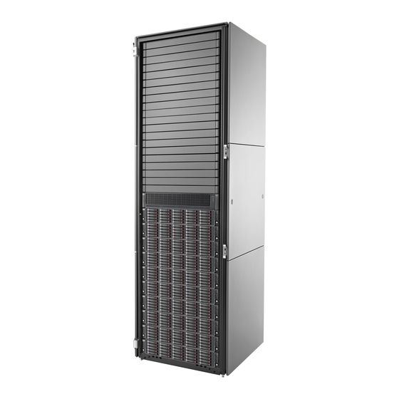
Page 29: Storage System Racks
Figure 12 P6500 Y-cable 1. Pull tab (may also be a release bar) 2. Port number label Storage system racks All storage system components are mounted in a rack. Each configuration includes one controller enclosure holding both controllers (the controller pair) and the disk enclosures. Each controller pair and all associated disk enclosures form a single storage system. -
Page 30: Power Distribution Units
Power distribution units AC power is distributed to the rack through a dual Power Distribution Unit (PDU) assembly mounted at the bottom rear of the rack (modular PDU) or on the rack (monitored PDU). The modular PDU may be mounted back-to-back either vertically (AC receptacles facing down and circuit breaker switches facing up) or horizontally (AC receptacles facing front and circuit breaker switches facing rear). -
Page 31: Pdms
Disables drive enclosures PS 2 Disables the controller PS 2 PDMs Depending on the rack, there can be up to eight PDMs mounted in the rear of the rack: The PDMs on the left side of the PDM pairs connect to PDU 1. The PDMs on the right side of the PDM pairs connect to PDU 2. -
Page 32: Moving And Stabilizing A Rack
Figure 14 Rack AC power distribution 1. PDU 1 6. PDM 2–1 2. PDM 1–1 7. PDM 2–2 3. PDM 1–2 8. PDM 2–3 4. PDM 1–3 9. PDM 2–4 5. PDM 1–4 10. PDU 2 Moving and stabilizing a rack WARNING! The physical size and weight of the rack requires a minimum of two people to move. - Page 33 Figure 15 Single rack configuration floor space requirements 1. Front door 5. Rear service area depth 300 mm 2. Rear door 6. Rack depth 1000 mm 3. Rack width 600 mm 7. Front service area depth 406 mm 4. Service area width 813 mm 8.
- Page 34 To stabilize the rack when it is in the final installation location: Use a wrench to lower the foot by turning the leveler foot hex nut clockwise until the caster does not touch the floor. Repeat for the other feet. After lowering the feet, check the rack to ensure it is stable and level.
-
Page 35: P6300/P6500 Eva Operation
2 P6300/P6500 EVA operation Best practices For useful information on managing and configuring your storage system, see the HP P6300/P6500 Enterprise Virtual Array configuration best practices white paper available at: http://h18006.www1.hp.com/storage/arraywhitepapers.html Operating tips and information Reserving adequate free space To ensure efficient storage system operation, reserve some unallocated capacity, or free space, in each disk group. -
Page 36: Failback Settings By Operating System
Table 7 Failback preference settings (continued) Setting Point in time Behavior Otherwise, the units are brought online to Controller 2. On controller failover All LUNs are brought online to the surviving controller. On controller failback All LUNs remain on the surviving controller. There is no failback except if a host moves the LUN using SCSI commands. -
Page 37: Changing Virtual Disk Failover/Failback Setting
Table 8 Failback settings by operating system (continued) Operating system Default behavior Supported settings Path A/B – Failover only Path A/B – Failover/Failback OpenVMS Host follows the unit No preference Path A/B – Failover only Path A/B – Failover/Failback (recommended) Oracle Solaris Host follows the unit No preference... -
Page 38: Recovery Cd
a read I/O request arrives on the non-managing controller, the read request must be transferred to the managing controller for servicing. The managing controller issues the I/O request, caches the read data, and mirrors that data to the cache on the non-managing controller, which then transfers the read data to the host. -
Page 39: Storage System Shutdown And Startup
The transceiver dust caps protect the transceivers from contamination. Do not discard the dust covers. CAUTION: To avoid damage to the connectors, always install the dust covers or dust caps whenever a transceiver or a fiber cable is disconnected. Remove the dust covers or dust caps from transceivers or fiber cable connectors only when they are connected. -
Page 40: Powering Off Disk Enclosures
Power on (or restart) the server with access to the disk enclosures, start the operating system, and log on as administrator. CAUTION: When you power on the server, the monitor might display a “New Hardware Found” message. Cancel out of this window to prevent the installation of unsupported software. Verify that each component is operating properly. -
Page 41: Restarting The Iscsi Or Iscsi/Fcoe Module
Turn on the SAN switches and wait for all switches to complete the power-on boot process. It may be necessary to wait several minutes for this to complete. NOTE: Before applying power to the rack PDUs, ensure that the power switch on the controller enclosure is off. -
Page 42: Using The Management Module
HP P6000 Command View is not supported. You must use the CLI to shut down the modules and then power cycle the array to power on the modules after the shutdown. To restart a module: Select the iSCSI controller in the navigation pane. Select Shutdown on the iSCSI Controller Properties window. -
Page 43: Connecting Through A Public Network
Figure 18 Management module 1. Status LEDs 3. Reset button 2. Ethernet jack Connecting through a public network Initialize the P6300 EVA or P6500 EVA storage system using HP P6000 Command View. If it is currently connected, disconnect the public network LAN cable from the back of the management module in the controller enclosure. -
Page 44: Connecting Through A Private Network
Remove the LAN cable to the private network or laptop and reconnect the cable to the public network. From a computer on the public network, browse to https://new IP:2373 and log in. The HP P6000 Control Panel GUI appears. Connecting through a private network Press and hold the recessed Reset button (3, Figure 18 (page 43)) for 4 to 5 seconds. -
Page 45: Saving Storage System Configuration Data
NOTE: Change your browser settings for the HP P6000 Control Panel as described in the HP P6000 Command View Installation Guide. You must have administrator privilege to change the settings in the HP P6000 Control Panel. To change the default operating mode: Connect to the management module using one of the methods described in “Connecting through a public network”... - Page 46 NOTE: For more information on using the utility, see the HP Storage System Scripting Utility Reference. See “Related documentation” (page 179). Double-click the SSSU desktop icon to run the application. When prompted, enter Manager (management server name or IP address), User name, and Password. Enter LS SYSTEM to display the storage systems managed by the management server.
-
Page 47: Saving Or Restoring The Iscsi Or Iscsi/Fcoe Module Configuration
Example 1 Saving configuration data on a Windows host Double-click on the SSSU desktop icon to run the application. When prompted, enter Manager (management server name or IP address), User name, and Password. Enter LS SYSTEM to display the storage systems managed by the management server. Enter SELECT SYSTEM system name, where system name is the name of the storage system. - Page 48 Figure 20 iSCSI Controller Configuration Selection window NOTE: A Restore action will reboot the module. P6300/P6500 EVA operation...
-
Page 49: Configuring Application Servers
3 Configuring application servers Overview This chapter provides general connectivity information for all the supported operating systems. Where applicable, an OS-specific section is included to provide more information. Clustering Clustering is connecting two or more computers together so that they behave like a single computer. Clustering is used for parallel processing, load balancing, and fault tolerance. -
Page 50: Testing Connections To The Array
Testing connections to the array After installing the FCAs, you can create and test connections between the host server and the array. For all operating systems, you must: Add hosts Create and present virtual disks Verify virtual disks from the hosts The following sections provide information that applies to all operating systems. -
Page 51: Creating And Presenting Virtual Disks
Creating and presenting virtual disks To create and present virtual disks to the host server: From HP P6000 Command View, create a virtual disk on the storage system. Specify values for the following parameters: Virtual disk name Vraid level Size Present the virtual disk to the host you added. -
Page 52: Creating Volume Groups On A Virtual Disk Using Vgcreate
# ioscan -fnCdisk # ioscan -fnCdisk Class H/W Patch Driver H/W Type Description State ======================================================================================== CLAIMED BUS_NEXUS Local PCI Bus Adapter (782) 0/6/0/0 CLAIMED INTERFACE HP Tachyon XL@ 2 FC Mass Stor Adap /dev/td2 0/6/0/0.39 CLAIMED INTERFACE FCP Domain ext_bus 0/6/00.39.13.0.0 fcparray CLAIMED... -
Page 53: Ibm Aix
IBM AIX Accessing IBM AIX utilities You can access IBM AIX utilities such as the Object Data Manager (ODM), on the following website: http://www.hp.com/support/downloads In the Search products box, enter MPIO, and then click AIX MPIO PCMA for HP Arrays. Select IBM AIX, and then select your software storage product. -
Page 54: Linux
Linux Driver failover mode If you use the INSTALL command without command options, the driver’s failover mode depends on whether a QLogic driver is already loaded in memory (listed in the output of the lsmod command). Possible driver failover mode scenarios include: If an hp_qla2x00src driver RPM is already installed, the new driver RPM uses the failover of the previous driver package. -
Page 55: Upgrading Linux Components
# modprobe qla2400 To reboot the server, enter the reboot command. CAUTION: If the boot device is attached to the SAN, you must reboot the host. To verify which RPM versions are installed, use the rpm command with the -q option. For example: # rpm -q hp_qla2x00src # rpm –q fibreutils... -
Page 56: Compiling The Driver For Multiple Kernels
Compiling the driver for multiple kernels If your system has multiple kernels installed on it, you can compile the driver for all the installed kernels by setting the INSTALLALLKERNELS environmental variable to y and exporting it by issuing the following commands: # INSTALLALLKERNELS=y # export INSTALLALLKERNELS You can also use the -a option of the INSTALL script as follows:... -
Page 57: Verifying Virtual Disks From The Host
This line identifies the location of the binary RPM. Copy the binary RPM to the production servers and install it using the following command: # rpm -ivh hp_qla2x00-version-revision.architecture.rpm Verifying virtual disks from the host To verify the virtual disks, first verify that the LUN is recognized and then verify that the host can access the virtual disks. -
Page 58: Adding Openvms Hosts
Table 1 1 Comparing console LUN to OS unit ID ID type System Display Console LUN ID set to 100 $1$GGA100: OS unit ID set to 50 $1$DGA50: Adding OpenVMS hosts To obtain WWNs on AlphaServers, do one of the following: Enter the show device fg/full OVMS command. -
Page 59: Configuring Virtual Disks From The Openvms Host
NOTE: The console LUN can be seen without any virtual disks presented. The LUN appears as $1$GGAx (where x represents the console LUN ID on the controller). After the system scans the fabric for devices, you can verify the devices with the SHOW DEVICE command: $ SHOW DEVICE NAME-OF-VIRTUAL-DISK/FULL For example, to display device information on a virtual disk named $1$DGA50, enter $ SHOW... -
Page 60: Setting Preferred Paths
Enter the following command to mount the disk: MOUNT/SYSTEM name-of-virtual-disk volume-label NOTE: The /SYSTEM switch is used for a single stand-alone system, or in clusters if you want to mount the disk only to select nodes. You can use the /CLUSTER switch for OpenVMS clusters. -
Page 61: Configuring Emulex Fcas With The Lpfc Driver
Update instructions depend on the version of your OS: For Solaris 9, install the latest Oracle StorEdge SAN software with associated patches. To locate the software, log into My Oracle Support: https://support.oracle.com/CSP/ui/flash.html Select the Patches & Updates tab and then search for StorEdge SAN Foundation Software 4.4 (formerly called StorageTek SAN 4.4). -
Page 62: Configuring Qlogic Fcas With The Qla2300 Driver
If using a single FCA and no multipathing, edit the following parameter to reduce the risk of data loss in case of a controller reboot: nodev-tmo=120; If using Veritas Volume Manager (VxVM) DMP for multipathing (single or multiple FCAs), edit the following parameter to ensure proper VxVM behavior: no-device-delay=0;... - Page 63 Ensure that you have the latest supported version of the qla2300 driver (see http:// www.hp.com/storage/spock). You must sign up for an HP Passport to enable access. For more information on how to use SPOCK, see the Getting Started Guide (http://h20272.www2.hp.com/Pages/spock_overview/ introduction.html).
-
Page 64: Fabric Setup And Zoning
If the qla2300 driver is version 4.15 or later, verify that the following or a similar entry is present in the /kernel/drv/sd.conf file: name="sd" parent="qla2300" target=2048; To perform LUN rediscovery after configuring the LUNs, use the following command: /opt/QLogic_Corporation/drvutil/qla2300/qlreconfig –d qla2300 -s Reboot the server to implement the changes to the configuration files. - Page 65 Go to http://support.veritas.com. Enter Storage Foundation for UNIX/Linux in the Product Lookup box. Enter EVA in the Enter keywords or phrase box, and then click the search symbol. To further narrow the search, select Solaris in the Platform box and search again. Read TechNotes and follow the instructions to download and install the ASL/APM.
-
Page 66: Configuring Virtual Disks From The Host
Example 4 Setting the I/O policy # vxdmpadm getattr arrayname EVA8100 iopolicy ENCLR_NAME DEFAULT CURRENT ============================================ EVA81000 Round-Robin Round-Robin # vxdmpadm setattr arrayname EVA81000 iopolicy=adaptive # vxdmpadm getattr arrayname EVA8100 iopolicy ENCLR_NAME DEFAULT CURRENT ============================================ EVA81000 Round-Robin Adaptive Configuring virtual disks from the host The procedure used to configure the LUN path to the array depends on the FCA driver. -
Page 67: Verifying Virtual Disks From The Host
50001fe1002709e9,5 Emulex (lpfc)/QLogic (qla2300) drivers: ◦ You can retrieve the WWPN by checking the assignment in the driver configuration file (the easiest method, because you then know the assigned target) or by using HBAnyware/SANSurfer. You can retrieve the WWLUN ID by using HBAnyware/SANSurfer. ◦... -
Page 68: Labeling And Partitioning The Devices
Example 5 Format command # format Searching for disks...done c2t50001FE1002709F8d1: configured with capacity of 1008.00MB c2t50001FE1002709F8d2: configured with capacity of 1008.00MB c2t50001FE1002709FCd1: configured with capacity of 1008.00MB c2t50001FE1002709FCd2: configured with capacity of 1008.00MB c3t50001FE1002709F9d1: configured with capacity of 1008.00MB c3t50001FE1002709F9d2: configured with capacity of 1008.00MB c3t50001FE1002709FDd1: configured with capacity of 1008.00MB c3t50001FE1002709FDd2: configured with capacity of 1008.00MB AVAILABLE DISK SELECTIONS:... -
Page 69: Vmware
For each new device, use the disk command to select another disk, and then repeat through Repeat this labeling procedure for each new device. (Use the disk command to select another disk.) When you finish labeling the disks, enter quit or press Ctrl+D to exit the format utility. For more information, see the System Administration Guide: Devices and File Systems for your operating system, available on the Oracle website: http://www.oracle.com/technetwork/... -
Page 70: Configuring An Esx Server
Configuring an ESX server This section provides information about configuring the ESX server. Loading the FCA NVRAM The FCA stores configuration information in the non-volatile RAM (NVRAM) cache. You must download the configuration for HP products. Perform one of the following procedures to load the NVRAM: If you have a ProLiant blade server: Download the supported FCA BIOS update, available on http://www.hp.com/support/... -
Page 71: Specifying Diskmaxlun
ESX 4.x commands The # esxcli nmp device setpolicy --device naa.6001438002a56f220001100000710000 --psp VMW_PSP_MRU command sets device naa.6001438002a56f220001100000710000 with an MRU multipathing policy. The # esxcli nmp device setpolicy --device naa.6001438002a56f220001100000710000 --psp VMW_PSP_FIXED command sets device naa.6001438002a56f220001100000710000 with a Fixed multipathing policy. The # esxcli nmp fixed setpreferred --device naa.6001438002a56f220001100000710000 --path vmhba1:C0:T2:L1 command sets device naa.6001438002a56f220001100000710000 with a Preferred multipathing... -
Page 72: Verifying Virtual Disks From The Host
Verifying virtual disks from the host To verify that the host can access the virtual disks, enter the more /proc/scsi/scsi command. The output lists all SCSI devices detected by the server. A P6300 EVA LUN entry looks similar to the following: Host: scsi3 Channel: 00 ID: 00 Lun: 01 Vendor: HP Model: HSV340... -
Page 73: Replacing Array Components
4 Replacing array components Customer self repair (CSR) Table 12 (page 74) Table 13 (page 75) identify hardware components that are customer replaceable. Using HP Insight Remote Support software or other diagnostic tools, a support specialist will work with you to diagnose and assess whether a replacement component is required to address a system problem. -
Page 74: Replaceable Parts
Figure 21 Example of typical product label 1. Spare component number Replaceable parts This product contains the replaceable parts listed in “Controller enclosure replacement parts ” (page 74) “Disk enclosure replaceable parts ” (page 75). Parts that are available for customer self repair (CSR) are indicated as follows: Mandatory CSR where geography permits. - Page 75 Table 12 Controller enclosure replacement parts (continued) Description Spare part number (non RoHS/RoHS) CSR status P6500 bezel assembly 583396–001 Y-cable, 2 m 583399–001 • SAS cable, SPS-CA, EXT Mini SAS, 2M 408767-001 • Table 13 Disk enclosure replaceable parts Description Spare part number (non RoHS/RoHS) CSR status Disk drive, 300 GB, 10K, SFF, 6G, M6625, SAS...
-
Page 76: Replacing The Failed Component
Replacing the failed component CAUTION: Components can be damaged by electrostatic discharge (ESD). Use proper anti-static protection. Always transport and store CRUs in an ESD protective enclosure. Do not remove the CRU from the ESD protective enclosure until you are ready to install it. Always use ESD precautions, such as a wrist strap, heel straps on conductive flooring, and an ESD protective smock when handling ESD sensitive equipment. - Page 77 HP Disk Enclosure Fan Interconnect Board Replacement Instructions HP Disk Enclosure Front Power UID interconnect board Replacement Instructions HP Disk Enclosure I/O Module Replacement Instructions HP Disk Enclosure VRM Replacement Instructions HP Disk Enclosure Rear Power UID Interconnect Board Replacement Instructions HP Power UID Replacement Instructions HP Disk Drive Replacement Instructions Replacement instructions...
-
Page 78: Iscsi Or Iscsi/Fcoe Configuration Rules And Guidelines
5 iSCSI or iSCSI/FCoE configuration rules and guidelines This chapter describes the iSCSI configuration rules and guidelines for the HP P6000 iSCSI and iSCSI/FCoE modules. iSCSI or iSCSI/FCoE module rules and supported maximums The iSCSI or iSCSI/FCoE modules are configured in a dual-controller configuration in the HP P6000. -
Page 79: Operating System And Multipath Software Support
Figure 22 FCoE support For the latest information on Fibre Channel over Ethernet switch model and firmware support, see the Single Point of Connectivity Knowledge (SPOCK) at http://www.hp.com/storage/spock. You must sign up for an HP Passport to enable access. Also, for information on FCoE configuration and attributes, see the HP SAN Design Reference Guide at: http://www.hp.com/go/sandesign NOTE:... -
Page 80: Iscsi Initiator Rules, Guidelines, And Support
Table 14 Operating system and multipath software support Operating system Multipath software Clusters Connectivity EVA storage system Apple Mac OS X None None iSCSI EVA4400/4400 with the embedded switch Microsoft Windows MPIO with HP DSM MSCS iSCSI, FCoE EVA4000/4100/6000/6 100/8000/8100 Server 2008, 2003, MPIO with Microsoft EVA6400/8400... -
Page 81: Linux Iscsi Initiator Rules And Guidelines
iSCSI Initiator operating system considerations: Host mode setting – Microsoft Windows 2008 or Windows 2003 TCPIP parameter Tcp1323Opts must be entered in the registry with a value of DWord=2 under the registry setting# HKEY_LOCAL_MACHINE\SYSTEM\CurrentControlSet\Ser¬vices\Tcpip\Parameters. The TimeOutValue parameter should be entered in the registry with a value of DWord=120 under the registry setting #HKEY_LOCAL_MACHINE\SYSTEM\CurrentControlSet\ Services\Disk. -
Page 82: Vmware Iscsi Initiator Rules And Guidelines
iSCSI Initiator operating system considerations: Host mode setting – Oracle Solaris Does not support TOE NICs or iSCSI HBA Does not support LUN 0 VMware iSCSI Initiator rules and guidelines The VMware iSCSI Initiator supports the following: Native iSCSI software initiator in VMware ESX 4.0/3.5 Guest OS SCSI Controller, LSI Logic and/or BUS Logic (BUS Logic with SUSE Linux only) ESX server's native multipath solution, based on NIC teaming on the server Guest OS boot from an iSCSI or an iSCSI/FCoE presented target device... -
Page 83: Set Up The Iscsi Initiator
Dedicated IP network for iSCSI data Jumbo frames NOTE: If you configure IPv6 on any iSCSI or iSCSI/FCoE module's ISCSI data port, you must also configure IPv6 on the HP P6000 Command View management server. Set up the iSCSI Initiator Windows For Windows Server 2008, the iSCSI initiator is included with the operating system. - Page 84 Install the HP P6000 iSCSI/FCoE and MPX200 Multifunction Router kit. Start the installer by running Launch.exe; if you are using a CD-ROM, the installer should start automatically. Click Install iSCSI/FCoE software package (see Figure 23 (page 84) Figure 24 (page 84)).
- Page 85 Figure 25 iSCSI Initiator Installation Click the Microsoft iSCSI Initiator icon to open the Control Panel applet. The iSCSI Initiator Properties window opens. Click the Discovery tab (see Figure 26 (page 85)). Figure 26 iSCSI Initiator Properties—Discovery tab In the Target Portals section, click Add. A dialog box opens to enter the iSCSI port IP Address.
- Page 86 Figure 27 iSCSI Initiator Properties—Discovery tab (Windows 2008) From HP P6000 Command View, click the EVA storage system icon to start the iSCSI storage presentation. In Figure 28 (page 86), the iSCSI or iSCSI/FCoE modules are the target EVA storage system. Figure 28 Adding a host b.
- Page 87 c. To create iSCSI Initiator host, click Add host. A dialog box opens. Enter a name for the initiator host in the Name box. Select iSCSI as the Type. Select the initiator iSCSI qualified name (IQN) from the iSCSI node name list. Select an OS from the Operating System list.
-
Page 88: Multipathing
Set up the iSCSI disk on the iSCSI Initiator: Open the iSCSI Initiator Control Panel applet. Click the Targets tab and then the Refresh button to see the available targets (Figure 31 (page 88)). The status should be Inactive. Figure 31 iSCSI Initiator Properties—Targets tab Select the target IQN, keying off the module 1 or 2 field and the WWN field, noted in Step 2.d, and click Log On. -
Page 89: Installing The Mpio Feature For Windows Server 2008
Microsoft MPIO support allows the initiator to log in to multiple sessions to the same target and aggregate the duplicate devices into a single device exposed to Windows. Each session to the target can be established using different NICs, network infrastructure, and target ports. If one session fails, another session can continue processing I/O without interruption to the application. - Page 90 Check the box for Multipath I/O in the Add Features page (Figure 32 (page 90)). Figure 32 Add Features page Click Next and then click Install. After the server reboots, add support for iSCSI Devices using the MPIO applet (see Figure 33 (page 90) Figure 34 (page 91)).
-
Page 91: Installing The Mpio Feature For Windows Server 2003
Figure 34 MPIO Properties page after reboot A final reboot is required to get the devices MPIO-ed. Installing the MPIO feature for Windows Server 2003 For Windows Server 2003, if you are installing the initiator for the first time, check all the installation option checkboxes and then click Next to continue (Figure 35 (page 91)). -
Page 92: About Microsoft Windows Server 2003 Scalable Networking Pack
About Microsoft Windows Server 2003 scalable networking pack The Microsoft Windows Server 2003 Scalable Networking Pack (SNP) contains functionality for offloading TCP network processing to hardware. TCP Chimney is a feature that allows TCP/IP processing to be offloaded to hardware. Receive Side Scaling allows receive packet processing to scale across multiple CPUs. -
Page 93: Set Up The Iscsi Initiator For Apple Mac Os X
Set up the iSCSI Initiator for Apple Mac OS X Install the ATTO iSCSI Macintosh Initiator v3.10 following the install instructions provided by the vendor. Set up the iSCSI Initiator... - Page 94 Run the Xtend SAN application to discover and configure the EVA iSCSI targets. The Xtend SAN iSCSI Initiator can discover targets either by static address or iSNS. For static address discovery: Select Discover Targets and then select Discover by DNS/IP (Figure 36 (page 94)).
- Page 95 For iSNS discovery: Select Initiator and then enter the iSNS name or IP address in the iSNS Address field (Figure 38 (page 95)). Figure 38 iSNS discovery and verification Test the connection from the initiator to the iSNS server by selecting Verify iSNS. If successful, select Save.
- Page 96 Select Status, select Network Node, and then select Login to connect to the module's target (Figure 40 (page 96)). The Network Node displays a status of Connected and the target status light turns green. Figure 40 Select status iSCSI or iSCSI/FCoE configuration rules and guidelines...
-
Page 97: Storage Setup For Apple Mac Os X
Storage setup for Apple Mac OS X Present LUNs using HP P6000 Command View. Verify that the EVA LUNs are presented to the Macintosh iSCSI Initiator: Open the Xtend SAN iSCSI application. Select the iSCSI or iSCSI/FCoE module target entry under the host name. Click the LUNs button. - Page 98 Figure 42 Configure initiator and targets Click the Discovered Targets tab and enter your iSCSI target IP address (Figure 43 (page 98)). Figure 43 Discovered Targets tab Log in to the target (Figure 44 (page 99)). iSCSI or iSCSI/FCoE configuration rules and guidelines...
-
Page 99: Installing And Configuring For Red Hat 5
Figure 44 Target login Click the Connected Targets tab, and then click the Toggle Start-Up button on each target listed so the targets start automatically (Figure 45 (page 99)). Figure 45 Connected Targets tab Installing and configuring for Red Hat 5 To install and configure for Red Hat 5: NOTE: The iSCSI driver package is included but is not installed by default. -
Page 100: Installing And Configuring For Red Hat 4 And Suse 9
Use the iscsiadm command to control discovery and connectivity: # iscsiadm –m discovery –t st –p 10.6.0.33:3260 Edit the initiator name: # vi /etc/iscsi/initiatorname.iscsi To start the iSCSI service use the service command: # service iscsi start Verify that the iSCSI service autostarts: #chkconfig iscsi on NOTE: For more detail, see the man pages regarding the iscsiadm open-iscsi administration... -
Page 101: Target Bindings
applications or operating system utilities to use the standard SCSI device nodes to access iSCSI devices can result in sending SCSI commands to the wrong target or logical unit. To provide consistent naming, the iSCSI driver scans the system to determine the mapping from SCSI device nodes to iSCSI targets. -
Page 102: Mounting File Systems
NOTE: Because of the way Linux dynamically allocates SCSI device nodes as SCSI devices are found, the driver does not and cannot ensure that any particular SCSI device node /dev/sda, for example, always maps to the same iSCSI TargetName. The symlinks described in “Assigning device names”... -
Page 103: Presenting Eva Storage For Linux
Presenting EVA storage for Linux To set up LUNs using HP P6000 Command View: Set up LUNs using HP P6000 Command View. For procedure steps, see Step Set up the iSCSI drive on the iSCSI Initiator: Restart the iSCSI services: /etc/rc.d/initd/iscsi restart Verify that the iSCSI LUNs are presented to the operating system by entering the following command:... - Page 104 Figure 47 Firewall Properties dialog box Select the Software iSCSI check box for to enable iSCSI traffic. Click OK. Enable the iSCSI software initiators: In the VMware VI client, select the server from the inventory panel. Click the Configuration tab, and then click Storage Adapters under Hardware. Under iSCSI Software Adapter, choose the available software initiator.
-
Page 105: Configuring Multipath With The Solaris 10 Iscsi Initiator
Figure 49 Add Send Target Server dialog box Enter the iSCSI IP address of the iSCSI or iSCSI/FCoE module. Click OK. To verify that the LUNs are presented to the VMware host, rescan for new iSCSI LUNs: In VMware’s VI client, select a server and click the Configuration tab. Choose Storage Adapters in the hardware panel and click Rescan above the Storage Adapters panel. -
Page 106: Mpxio Overview
MPxIO overview The Oracle multipathing software (MPxIO) provides basic failover and load-balancing capability to HP P6000, and EVA4x00/6x00/8x00 storage systems. MPxIO allows the merging of multiple SCSI layer paths, such as an iSCSI device exposing the same LUN via several different iSCSI target names. - Page 107 Modify load balancing to none: load-balance="none"; Modify auto-failback to disable: auto-failback="disable"; Add the following lines to cover the 4x00/6x00/8x00 HP arrays: device-type-scsi-options-list = HP HSV , symmetric-option ; symmetric-option = 0x1000000; NOTE: You must enter six spaces between HP and HSV, as shown. Example: HP storage array settings in /kernel/drv/scsi_vhci.conf: # Copyright 2004 Sun Microsystems, Inc.
-
Page 108: Enable Iscsi Target Discovery
# devices on your system. Please refer to sgen(7d) for details. # sgen may be configured to bind to SCSI devices exporting a particular device # type, using the device-type-config-list, which is a ',' delimited list of # strings. device-type-config-list="array_ctrl"; # After configuring the device-type-config-list and/or the inquiry-config-list, # the administrator must uncomment those target/lun pairs at which there are # devices for sgen to control. -
Page 109: Modify Target Parameter Maxrecvdataseglen
To enable iSCSI target discovery: Enable Sendtargets discovery: # iscsiadm modify discovery –t enable Verify SendTargets setting is enabled: # iscsiadm list discovery The iSCSI or iSCSI/FCoE module has multiple iSCSI ports available to the Solaris iSCSI initiator. To discover the targets available, enter the following command for each iSCSI port IP address that the iSCSI initiator will access: #iscsiadm add discovery-address ‘iscsi port IP address’... -
Page 110: Monitor Multipath Devices
Target: iqn.2004-09.com.hp.fcgw.mez50.1.01.50014380025da538 Alias: - Bi-directional Authentication: disabled Authentication Type: NONE Login Parameters (Default/Configured): Data Sequence In Order: yes/- Data PDU In Order: yes/- Default Time To Retain: 20/- Default Time To Wait: 2/- Error Recovery Level: 0/- First Burst Length: 65536/- Immediate Data: yes/- Initial Ready To Transfer (R2T): yes/- Max Burst Length: 262144/-... -
Page 111: Managing And Troubleshooting Solaris Iscsi Multipath Devices
mpathadm show lu ‘logical-unit’ This command lists details regarding a specific logical unit. This command can help verify symmetric mode, load balancing, and autofailback settings, as well as path and target port information. Example: #mpathadm show lu /dev/rdsk/c5t600508B4000B15A200005000038E0000d0s2 Logical Unit: /dev/rdsk/c5t600508B4000B15A200005000038E0000d0s2 mpath-support: libmpscsi_vhci.so... -
Page 112: Load Balancing Features Of Microsoft Mpio For Iscsi
Select the desired options on the Load Balance Policy menu to set the policy. Figure 51 iSCSI Initiator MPIO properties Load balancing features of Microsoft MPIO for iSCSI The features of Microsoft MPIO for iSCSI include the following: Failover Only. No load balancing is performed. There is a single active path and the rest of the paths are standby paths. -
Page 113: Microsoft Mpio With Qlogic Iscsi Hba
Microsoft MPIO with QLogic iSCSI HBA The QLogic iSCSI HBA is supported in a multipath Windows configuration that is used in conjunction with Microsoft iSCSI Initiator Services and Microsoft MPIO. Because the iSCSI driver resides on board the QLogic iSCSI HBA, it is not necessary to install the Microsoft iSCSI Initiator. Installing the QLogic iSCSI HBA Install the QLogic iSCSI HBA hardware and software following the instructions in the QLogic installation manual. -
Page 114: Adding Targets To Qlogic Iscsi Initiator
Click Yes to start the general configuration wizard (see Figure 54 (page 114)). Use the Wizard Choose iSCSI HBA port to configure the QLogic iSCSI HBA. Configure HBA Port network settings. Configure HBA Port DNS settings (optional). Configure SLP Target Discovery settings (optional). Configure iSNS Target Discovery settings (optional). -
Page 115: Presenting Luns To The Qlogic Iscsi Initiator
Figure 55 HBA Port Target Configuration Repeat Steps 1 and 2 to add each additional iSCSI or iSCSI/FCoE target iSCSI port. Click Next. To enable the changes, enter the SMS password: config. Select the Target Settings tab. Verify that the HBA state is Ready, Link Up and each target entry’s state is Session Active (Figure 56 (page 115)). -
Page 116: Installing The Hp Mpio Full Featured Dsm For Eva
Follow procedures in Step 2 Create an iSCSI host. Present LUNs to the iSCSI host. On the iSCSI HBA tab (Figure 57 (page 116) verify that the QLogic iSCSI HBA is connected to the iSCSI LUNs in SMS under the HBA iSCSI port. Figure 57 HBA iSCSI port connections Use Microsoft’s iSCSI services to manage the iSCSI target login and LUN load balancing policies. -
Page 117: Microsoft Windows Cluster Support
Figure 58 Example: HP MPIO DSM Manager with iSCSI devices Microsoft Windows Cluster support Microsoft Cluster Server for Windows 2003 iSCSI failover clustering is supported by the iSCSI or iSCSI/FCoE modules. For more information, see: http://www.microsoft.com/windowsserver2003/technologies/storage/ iscsi/iscsicluster.mspx Requirements Operating system: Windows Server 2003 Enterprise, SP2, R2, x86/x64 Firmware: minimum version—3.1.0.0, released November 2009 Initiator: Persistent Reservation registry key—for Microsoft Generic DSM... -
Page 118: Microsoft Cluster Server For Windows 2008
Figure 59 iSCSI Persistent Reservation Setup window Click Done to finish. Each cluster is required to have its own value, and each node of a single cluster must have its own value. For example, Cluster A could have the default setting of AABBCCCCBBAA. Possible node settings: Node 1 Node 2... -
Page 119: Setting Up Authentication
Setting up authentication Challenge Handshake Authentication Protocol (CHAP) is an authentication protocol used for secure logon between the iSCSI Initiator and iSCSI target. CHAP uses a challenge-response security mechanism for verifying the identity of an initiator without revealing a secret password that is shared by the two entities. -
Page 120: Linux Version
Linux version CHAP is supported with Linux open-iscsi Initiator and the iSCSI or iSCSI/FCoE modules. CHAP setup with Linux iSCSI Initiator is not supported with the iSCSI or iSCSI/FCoE modules. ATTO Macintosh Chap restrictions The ATTO Macintosh iSCSI Initiator does not support CHAP at this time. Recommended CHAP policies The same CHAP secret should not be configured for authentication of multiple initiators or multiple targets. - Page 121 Table 18 iSCSI or iSCSI/FCoE module secret settings iSCSI or iSCSI/FCoE module secret settings MS Initiator secret settings Source Setting (example) Action Setting (example) iSCSI Port General Tab Secret Discovered iSCSI Initiator CHAPsecret01 Add Target Portal CHAPsecret01 iSCSI Presented Target Log on to Target CHAPsecret01 NOTE:...
-
Page 122: Enabling Chap For The Iscsi Or Iscsi/Fcoe Module-Discovered Iscsi Initiator Entry
Enable CHAP for the Microsoft iSCSI Initiator: Click Discovery. For manually discovering iSCSI target portals: Click Add under Target Portals. Enter the IP address of the iSCSI port of the iSCSI or iSCSI/FCoE module. Click Advanced. Select the CHAP Login Information check box. Enter the CHAP secret for the iSCSI or iSCSI/FCoE modules discovered iSCSI Initiator in the Target Secret box. -
Page 123: Enable Chap For The Microsoft Iscsi Initiator
Enable CHAP for the Microsoft iSCSI Initiator Click Discovery. For manually discovering iSCSI target portals: Click Add under Target Portals. Enter the IP address of the iSCSI port of the iSCSI or iSCSI/FCoE module. Click Advanced. Select the CHAP Login Information checkbox. Enter the CHAP secret for the iSCSI or iSCSI/FCoE module's-discovered iSCSI Initiator in the Target Secret box, for example, CHAPsecret01. -
Page 124: Enabling Single-Direction Chap During Discovery And Bi-Directional Chap During Normal Session
Using the iscsiadm do a login into the iSCSI Target. For example: [root@sanergy33 iscsi]# iscsiadm --mode node --targetname iqn.2004-09.com.hp.fcgw.mez50.1.01.50014380025da538 --login The following is a sample iscsid.conf file for CHAP: # ************* # CHAP Settings # ************* # To enable CHAP authentication set node.session.auth.authmethod # to CHAP. - Page 125 Enable CHAP for the iSCSI or iSCSI/FCoE controller-discovered iSCSI Initiator entry. CHAP can be enabled via CLI only. To enable CHAP for the iSCSI or iSCSI/FCoE controller-discovered iSCSI Initiator entry using the iSCSI or iSCSI/FCoE controller CLI: If the iSCSI Initiator is not listed under the set chap command: HP Command View Option: add the initiator iqn name string via HP Command View’s Add Host tab.
-
Page 126: Enabling Bi-Directional Chap During Discovery And Single-Direction Chap During Normal Session
Enable CHAP for the Microsoft iSCSI Initiator. Click the General tab. Click Secret in the middle of the screen. Click Reset. Enter the iSCSI or iSCSI/FCoE controller iSCSI Presented Target CHAP secret. For example: hpstorageworks. Click Discovery. For manually discovering iSCSI target portals: Click Add under Target Portals. - Page 127 Enable CHAP for the iSCSI or iSCSI/FCoE controller discovered iSCSI Initiator entry. CHAP can be enabled via CLI only. To enable CHAP for the iSCSI or iSCSI/FCoE controller discovered iSCSI Initiator entry using the iSCSI or iSCSI/FCoE controller CLI: If the iSCSI Initiator is not listed under the set chap command: HP Command View Option: add the initiator iqn name string via the HP Command View Add Host tab.
-
Page 128: Enabling Bi-Directional Chap During Discovery And Bi-Directional Chap During Normal Session
Enable CHAP for the Microsoft iSCSI Initiator. Click the General tab. Click Secret in the middle of the screen. Click Reset. Enter the iSCSI or iSCSI/FCoE controller iSCSI Presented Target CHAP secret. For example: hpstorageworks. Click OK. Click Discovery. For manually discovering iSCSI target portals: Click Add under Target Portals. - Page 129 Enable CHAP for the iSCSI or iSCSI/FCoE controller discovered iSCSI Initiator entry. CHAP can be enabled via CLI only. To enable CHAP for the iSCSI or iSCSI/FCoE controller discovered iSCSI Initiator entry using the iSCSI or iSCSI/FCoE controller CLI: If the iSCSI Initiator is not listed under set chap command: HP Command View Option: add the initiator iqn name string via Command View’s Add Host tab.
-
Page 130: Enable Chap For The Open-Iscsi Iscsi Initiator
Enable CHAP for the Microsoft iSCSI Initiator. Click the General tab. Click Secret in the middle of the screen. Click Reset. Enter the iSCSI or iSCSI/FCoE controller iSCSI Presented Target CHAP secret. For example: hpstorageworks. Click OK. Click Discovery. For manually discovering iSCSI target portals: Click Add under Target Portals. - Page 131 Setup Username and Password for Initiator and Portal for Discovery Session. For example: # To set a discovery session CHAP username and password for the initiator # authentication by the target(s), uncomment the following lines: #discovery.sendtargets.auth.username = username #discovery.sendtargets.auth.password = password discovery.sendtargets.auth.username = iqn.1994-05.com.redhat:fc813cac13.sanergy33 #discovery.sendtargets.auth.password = CHAPSecret01 # To set a discovery session CHAP username and password for target(s)
-
Page 132: Single Path Implementation
6 Single path implementation This chapter provides guidance for connecting servers with a single path host bus adapter (HBA) to the Enterprise Virtual Array (EVA) storage system with no multipath software installed. A single path HBA is defined as: A single HBA port to a switch with no multipathing software installed A single HBA port to a switch with multipathing software installed HBA LUNs are not shared by any other HBA in the server or in the SAN. -
Page 133: Supported Configurations
Because of the risks of using servers with a single path HBA, HP recommends the following actions: Use servers with a single path HBA that are not mission-critical or highly available. Perform frequent backups of the single path server and its storage. Supported configurations All examples detail a small homogeneous Storage Area Network (SAN) for ease of explanation. - Page 134 Figure 60 Single path HBA server without OpenVMS 1. Network interconnection 6. SAN switch 1 2. Single HBA server (Host 1) 7. SAN switch 2 3. Dual HBA server (Host 2) 8. Fabric zone 4. Management server 9. Controller A 5.
-
Page 135: Hp-Ux Configuration
HP-UX configuration Requirements Proper switch zoning must be used to ensure each single path HBA has an exclusive path to its LUNs. Single path HBA server can be in the same fabric as servers with multiple HBAs. Single path HBA server cannot share LUNs with any other HBAs. In the use of snapshots and snapclones, the source virtual disk and all associated snapshots and snapclones must be presented to the single path hosts that are zoned with the same controller. -
Page 136: Windows Server 2003 (32-Bit) And Windows Server 2008 (32-Bit) Configurations
Figure 62 HP-UX configuration 1. Network interconnection 5. SAN switch 1 2. Single HBA server (Host 1) 6. SAN switch 2 3. Dual HBA server (Host 2) 7. Controller A 4. Management server 8. Controller B Windows Server 2003 (32-bit) and Windows Server 2008 (32–bit) configurations Requirements Switch zoning or controller level SSP must be used to ensure each single path HBA has an... -
Page 137: Limitations
NOTE: For additional risks, see “Windows Servers” (page 148). Limitations HP P6000 Continuous Access is not supported with single path configurations. Single path HBA server is not part of a cluster. Booting from the SAN is not supported on single path HBA servers. Figure 63 Windows Server 2003 (32-bit) and Windows 2008 (32–bit) configuration 1. -
Page 138: Risks
Risks Single path failure will result in loss of connection with the storage system. Single path failure may cause the server to reboot. Controller shutdown puts controller in a failed state that results in loss of data accessibility and loss of host data that has not been written to storage. NOTE: For additional risks, see “Windows Servers”... -
Page 139: Hba Configuration
becomes an ordinary virtual disk, you may present that virtual disk as you would any other ordinary virtual disk. HBA must be properly configured to work in a single HBA server configuration. The user is required to: ◦ Download and extract the contents of the TAR file. HBA configuration Host 1 is a single path HBA host. -
Page 140: Openvms Configuration
OpenVMS configuration Requirements Switch zoning or controller level SSP must be used to ensure each single path HBA has an exclusive path to its LUNs. All nodes with direct connection to a disk must have the same access paths available to them. Single path HBA server can be in the same fabric as servers with multiple HBAs. -
Page 141: Limitations
Limitations HP P6000 Continuous Access is not supported with single path configurations. Figure 66 OpenVMS configuration 1. Network interconnection 5. SAN switch 1 2. Single HBA server (Host 1) 6. SAN switch 2 3. Dual HBA server (Host 2) 7. Controller A 4. -
Page 142: Risks
Risks Single path failure may result in data loss or disk corruption. Limitations HP P6000 Continuous Access is not supported with single path configurations. Single path HBA server is not part of a cluster. Booting from the SAN is not supported. Figure 67 Xen configuration 1. -
Page 143: Hba Configuration
HBA configuration Host 1 is a single path HBA. Host 2 is a dual HBA host with multipathing software. Figure 68 (page 143). Risks Single path failure may result in data loss or disk corruption. NOTE: For additional risks, see “Linux”... -
Page 144: Hba Configuration
controller. In the case of snapclones, after the cloning process has completed and the clone becomes an ordinary virtual disk, you may present that virtual disk as you would any other ordinary virtual disk. Linux 64-bit servers can support up to 14 single or dual path HBAs per server. Switch zoning and SSP are required to isolate the LUNs presented to each HBA from each other. -
Page 145: Ibm Aix Configuration
IBM AIX configuration Requirements Switch zoning or controller level SSP must be used to ensure each single path HBA has an exclusive path to its LUNs. Single path HBA server can be in the same fabric as servers with multiple HBAs. Single path HBA server cannot share LUNs with any other HBAs. -
Page 146: Vmware Configuration
Figure 70 IBM AIX Configuration 1. Network interconnection 5. SAN switch 1 2. Single HBA server (Host 1) 6. SAN switch 2 3. Dual HBA server (Host 2) 7. Controller A 4. Management server 8. Controller B VMware configuration Requirements Switch zoning or controller level SSP must be used to ensure each single path HBA has an exclusive path to its LUNs. -
Page 147: Limitations
Limitations HP P6000 Continuous Access is not supported with single path configurations. Single HBA path at the host server is not part of a cluster, unless in a VMware High Availability Cluster. Booting from the SAN is supported on single path HBA servers. Figure 71 VMware configuration 1. -
Page 148: Windows Servers
Fault stimulus Failure effect Server path failure Short term: Data transfer stops. Possible I/O errors. Long term: Job hangs, cannot umount disk, fsck failed, disk corrupted, need mkfs disk. Storage path failure Short term: Data transfer stops. Possible I/O errors. Long term: Job hangs, replace cable, I/O continues. -
Page 149: Linux
Fault stimulus Failure effect to a different served path. When the single-path node crashes, only the processes executing on that node fail. In either case, no data is lost or corrupted. Switch failure (SAN switch disabled) I/O is suspended or process is terminated across this HBA until switch is back online. -
Page 150: Ibm Aix
Fault stimulus Failure effect Server path failure Short: I/O suspended, possible data loss. Long: I/O halts with I/O errors, data loss. HBA driver must be reloaded before failed drives can be recovered, fsck should be run on any failed drives before remounting. Storage path failure Short: I/O suspended, possible data loss. -
Page 151: Mac Os
Fault stimulus Failure effect Server path failure Short: I/O suspended, possible data loss. Long: I/O halts with I/O errors, data loss. HBA driver must be reloaded before failed drives can be recovered, fsck should be run on any failed drives before remounting. Storage path failure Short: I/O suspended, possible data loss. -
Page 152: Troubleshooting
7 Troubleshooting If the disk enclosure does not initialize IMPORTANT: After a power failure, the system automatically returns to the last-powered state (On or Off) when A/C power is restored. Ensure that the power on/standby button was pressed firmly and held for approximately three seconds. -
Page 153: Is The Power On/Standby Button Led Amber
Is the power on/standby button LED amber? Answer Possible Reasons Possible Solutions System functioning properly. No action required. The power on/standby button has Firmly press the power on/standby not been pressed firmly or held button and hold for approximately long enough. three seconds. -
Page 154: Is The Fan Led Amber
Is the fan LED amber? Answers Possible Reasons Actions Functioning properly. No action required Fan might not be inserted properly, Be sure that the fan is undamaged might have a damaged connector, or and is fully seated. might have failed. Contact an authorized service provider for assistance. -
Page 155: Automatic Data Recovery (Rebuild)
Automatic data recovery (rebuild) When you replace a disk drive in an array, the controller uses the fault-tolerance information on the remaining drives in the array to reconstruct the missing data (the data that was originally on the replaced drive) and write it to the replacement drive. This process is called automatic data recovery, or rebuild. -
Page 156: Iscsi Module Diagnostics And Troubleshooting
The controller reconstructs the information on the new drive, based on information from the remaining physical drives in the logical drive. While reconstructing the data on hot-plug drives, the online LED flashes. When the drive rebuild is complete, the online LED is illuminated. iSCSI module diagnostics and troubleshooting Diagnostic information is also available through HP P6000 Command View and the CLI event logs and error displays. -
Page 157: Iscsi Or Iscsi/Fcoe Module's Log Data
Enter the CLI command beacon on (see Figure 73 (page 157)). Figure 73 Beacon on command 2. In HP P6000 Command View, click the General tab and then click the Locate button. Use the Locate ON and Locate OFF buttons to control the blue LED (see Figure 74 (page 157)). -
Page 158: Issues And Solutions
Figure 75 iSCSI and iSCSI/FCoE module properties Issues and solutions Issue: HP P6000 Command View does not discover the iSCSI or iSCSI/FCoE modules Solution 1: Ensure that a DHCP server is available. Solution 2: Set a static IP address on each iSCSI and iSCSI/FCoE module through the CLI. Solution 3: Ensure the HP P6000 Command View station is on the same subnet of the management ports. -
Page 159: Issue: Initiator Logs In To Iscsi Or Iscsi/Fcoe Controller Target But Eva Assigned Luns Are Not Appearing On The Initiator
Figure 76 IP Ports tab Issue: Initiator logs in to iSCSI or iSCSI/FCoE controller target but EVA assigned LUNs are not appearing on the initiator Solution 1. The initiator needs to log in to the target where the EVA LUN was assigned. Solution 2. -
Page 160: Issue: Windows Initiators May Display Reconnecting If Nic Mtu Changes After Connection Has Logged In
Figure 77 Host details Figure 78 Target tab Issue: Windows initiators may display Reconnecting if NIC MTU changes after connection has logged in. Solution. Log out of those sessions and Log On again to re-establish the Connected state. Issue: When communication between HP P6000 Command View and iSCSI or iSCSI/FCoE module is down, use following options: Solution 1. -
Page 161: Hp P6000 Command View Issues And Solutions
Enter a valid IPv4 mgmt Ip address under Mgmt Port and click the Save changes button. If only IPv6 mgmt port IP address is set, enter a valid lPv6 management IP address under Mgmt Port and click the Save changes button. NOTE: If you configure IPv6 on any iSCSI or iSCSI/FCoE module’s iSCSI port, you must also configure IPv6 on the HP P6000 Command View EVA management server. -
Page 162: Error Messages
8 Error messages This list of error messages is in order by status code value, 0 to 243. Table 23 Error Messages Status code value Meaning How to correct The SCMI command completed successfully. No corrective action required. Successful Status The object or relationship already exists. - Page 163 Table 23 Error Messages (continued) Status code value Meaning How to correct The supplied handle is invalid. This can In the following cases, the message Invalid Parameter handle indicate a user error, program error, or a can occur because the operation is storage cell in an uninitialized state.
- Page 164 Table 23 Error Messages (continued) Status code value Meaning How to correct Several states can cause this message: Case 1: Either delete the associated Objects in your system are in use, Case 1: The operation cannot be performed object or resolve the in progress state. and their state prevents the because an association exists a related Case 2: Report the error to product...
- Page 165 Table 23 Error Messages (continued) Status code value Meaning How to correct The operation cannot be performed because Report the error to product support. Target Object Does Not Exist the object does not exist. This can indicate a user or program error. A timeout has occurred in processing the Verify the hardware connections and Timeout...
- Page 166 Table 23 Error Messages (continued) Status code value Meaning How to correct The operation cannot be performed because Configure the virtual disk to be a Not DR group member the virtual disk is not a member of a member of a Continuous Access group Continuous Access group.
- Page 167 Table 23 Error Messages (continued) Status code value Meaning How to correct Case 1: The maximum number of items Case 1: If this operation is still desired, Maximum Number of Objects allowed has been reached. delete one or more of the items and Exceeded.
- Page 168 Table 23 Error Messages (continued) Status code value Meaning How to correct This error is no longer supported. Report the error to product support. Obsolete This error is no longer supported. Report the error to product support. Obsolete The firmware image file is incompatible with Retrieve a valid firmware image file Image incompatible the current system configuration.
- Page 169 Table 23 Error Messages (continued) Status code value Meaning How to correct The disk volume is already a part of a disk Resolve the condition by setting the Invalid Volume Usage group. usage to a reserved state, wait for the usage to change to this state, and retry the request.
- Page 170 Table 23 Error Messages (continued) Status code value Meaning How to correct The remote Continuous Access group Correctly select the remote Continuous Unknown remote DR group specified does not exist. Access group retry the request. This error is no longer supported. Report the error to product support.
- Page 171 Table 23 Error Messages (continued) Status code value Meaning How to correct Snapclone Active 1 1 1 The operation cannot be completed while Wait several minutes for the drive EMU Load Busy the drive enclosures are undergoing code enclosure code load to finish, then load.
- Page 172 Table 23 Error Messages (continued) Status code value Meaning How to correct EVA 6400/8400 only. A generic error was Ensure other OCP is on and try again. OCP Error detected with the OCP interface. If the problem persists, report the error to product support.
- Page 173 Table 23 Error Messages (continued) Status code value Meaning How to correct An unsupported code load attempt was Code load the EVA firmware with a Specified Option Iis Not Yet made. supported method. Implemented Data replication group is already Disable active-active or read-only and DRM Group Is Already “Present present_only.
- Page 174 Table 23 Error Messages (continued) Status code value Meaning How to correct The system has reached the limit of client Remove an adapter connection before Too Many Port WWNs adapters, so the command attempted cannot attempting the command again. add another. The port WWN supplied with the command Retry the command with an accurate Port WWN Not Found...
- Page 175 Table 23 Error Messages (continued) Status code value Meaning How to correct The supplied list of drives contained multiple Correct the list such that only one type Mixed Drive Types drive types. of drive is used. An attempt to enable the OCP Locate LED No corrective action required.
- Page 176 Table 23 Error Messages (continued) Status code value Meaning How to correct Attempt to create a data replication group Verify/re-establish communication to No Path To DR Destination failed because of a loss of communication the remote site. with the remote site. This error is no longer supported.
- Page 177 Table 23 Error Messages (continued) Status code value Meaning How to correct Storage Cell Not Locked. The requestor must Retry the operation later. If the error Fail Not Locked have a valid command lock before persists, report the error to product attempting this command.
- Page 178 Table 23 Error Messages (continued) Status code value Meaning How to correct The event was not found. Report the error to product support. Event Not Found There were not enough drives to complete Replace the unsupported drives with Unsupported Drive the operation and some unsupported drives supported drives and retry.
-
Page 179: Support And Other Resources
9 Support and other resources Contacting HP HP technical support For worldwide technical support information, see the HP support website: http://www.hp.com/support Before contacting HP, collect the following information: Product model names and numbers Technical support registration number (if applicable) Product serial numbers Error messages Operating system type and revision level Detailed questions... -
Page 180: Typographic Conventions
HP Software Downloads: http://www.hp.com/support/manuals HP Software Depot: http://www.software.hp.com HP Single Point of Connectivity Knowledge (SPOCK): http://www.hp.com/storage/spock HP SAN manuals: http://www.hp.com/go/sdgmanuals Typographic conventions Table 24 Document conventions Convention Element Blue text: Table 24 (page 180) Cross-reference links and e-mail addresses Blue, underlined text: http://www.hp.com Website addresses Bold text... -
Page 181: Rack Stability
parts do not qualify for CSR. Your HP-authorized service provider will determine whether a repair can be accomplished by CSR. For more information about CSR, contact your local service provider, or see the CSR website: http://www.hp.com/go/selfrepair Rack stability Rack stability protects personnel and equipment. WARNING! To reduce the risk of personal injury or damage to equipment: Extend leveling jacks to the floor. -
Page 182: A Regulatory Compliance Notices
A Regulatory compliance notices Regulatory compliance identification numbers For the purpose of regulatory compliance certifications and identification, this product has been assigned a unique regulatory model number. The regulatory model number can be found on the product nameplate label, along with all required approval markings and information. When requesting compliance information for this product, always refer to this regulatory model number. -
Page 183: Declaration Of Conformity For Products Marked With The Fcc Logo, United States Only
Or call 1-281-514-3333 Modification The FCC requires the user to be notified that any changes or modifications made to this device that are not expressly approved by Hewlett-Packard Company may void the user's authority to operate the equipment. Cables When provided, connections to this device must be made with shielded cables with metallic RFI/EMI connector hoods in order to maintain compliance with FCC Rules and Regulations. -
Page 184: Japanese Notices
This compliance is indicated by the following conformity marking placed on the product: This marking is valid for non-Telecom products and EU harmonized Telecom products (e.g., Bluetooth). Certificates can be obtained from http://www.hp.com/go/certificates. Hewlett-Packard GmbH, HQ-TRE, Herrenberger Strasse 140, 71034 Boeblingen, Germany Japanese notices Japanese VCCI-A notice Japanese VCCI-B notice... -
Page 185: Class B Equipment
Class B equipment Taiwanese notices BSMI Class A notice Taiwan battery recycle statement Turkish recycling notice Türkiye Cumhuriyeti: EEE Yönetmeliğine Uygundur Vietnamese Information Technology and Communications compliance marking Taiwanese notices 185... -
Page 186: Laser Compliance Notices
Laser compliance notices English laser notice This device may contain a laser that is classified as a Class 1 Laser Product in accordance with U.S. FDA regulations and the IEC 60825- 1 . The product does not emit hazardous laser radiation. WARNING! Use of controls or adjustments or performance of procedures other than those specified herein or in the laser product's installation guide may result in hazardous radiation... -
Page 187: German Laser Notice
German laser notice Italian laser notice Japanese laser notice Laser compliance notices 187... -
Page 188: Spanish Laser Notice
Spanish laser notice Recycling notices English recycling notice Disposal of waste equipment by users in private household in the European Union This symbol means do not dispose of your product with your other household waste. Instead, you should protect human health and the environment by handing over your waste equipment to a designated collection point for the recycling of waste electrical and electronic equipment. -
Page 189: Dutch Recycling Notice
Dutch recycling notice Inzameling van afgedankte apparatuur van particuliere huishoudens in de Europese Unie Dit symbool betekent dat het product niet mag worden gedeponeerd bij het overige huishoudelijke afval. Bescherm de gezondheid en het milieu door afgedankte apparatuur in te leveren bij een hiervoor bestemd inzamelpunt voor recycling van afgedankte elektrische en elektronische apparatuur. -
Page 190: Hungarian Recycling Notice
Hungarian recycling notice A hulladék anyagok megsemmisítése az Európai Unió háztartásaiban Ez a szimbólum azt jelzi, hogy a készüléket nem szabad a háztartási hulladékkal együtt kidobni. Ehelyett a leselejtezett berendezéseknek az elektromos vagy elektronikus hulladék átvételére kijelölt helyen történő beszolgáltatásával megóvja az emberi egészséget és a környezetet.További információt a helyi köztisztasági vállalattól kaphat. -
Page 191: Portuguese Recycling Notice
Portuguese recycling notice Descarte de equipamentos usados por utilizadores domésticos na União Europeia Este símbolo indica que não deve descartar o seu produto juntamente com os outros lixos domiciliares. Ao invés disso, deve proteger a saúde humana e o meio ambiente levando o seu equipamento para descarte em um ponto de recolha destinado à... -
Page 192: Battery Replacement Notices
Battery replacement notices Dutch battery notice French battery notice 192 Regulatory compliance notices... -
Page 193: German Battery Notice
German battery notice Italian battery notice Battery replacement notices 193... -
Page 194: Japanese Battery Notice
Japanese battery notice Spanish battery notice 194 Regulatory compliance notices... -
Page 195: B Non-Standard Rack Specifications
B Non-standard rack specifications The appendix provides information on the requirements when installing the P6300/P6500 EVA in a non-standard rack. All the requirements must be met to ensure proper operation of the storage system. Internal component envelope EVA component mounting brackets require space to be mounted behind the vertical mounting rails. Room for the mounting of the brackets includes the width of the mounting rails and needed room for any mounting hardware, such as screws, clip nuts, etc. -
Page 196: Weights, Dimensions And Component Cg Measurements
Weights, dimensions and component CG measurements Cabinet CG dimensions are reported as measured from the inside bottom of the cabinet (Z), the leading edge of the vertical mounting rails (Y), and the centerline of the cabinet mounting space (X). Component CG measurements are measured from the bottom of the U space the component is to occupy (Z), the mounting surface of the mounting flanges (Y), and the centerline of the component (X). -
Page 197: Shock And Vibration Specifications
Table 25 HP UPS models and capacities UPS Model Capacity (in watts) R1500 1340 R3000 2700 R5500 4500 R12000 12000 Table 26 UPS operating time limits Minutes of operation Load (percent) With standby battery With 1 ERM With 2 ERMs R1500 R3000 R5500... - Page 198 Table 27 Operating Shock/Vibration Shock test with half sine pulses of 10 G magnitude and 10 ms duration applied in all three axes (both positive and negative directions). Sine sweep vibration from 5 Hz to 500 Hz to 5 Hz at 0.1 G peak, with 0.020” displacement limitation below 10 Hz.
-
Page 199: C Command Reference
C Command reference This chapter lists and describes the P6000 iSCSI and iSCSI/FCoE module's CLI commands in alphabetical order. Each command description includes its syntax, keywords, notes, and examples. Command syntax The HP P6000 iSCSI or iSCSI/FCoE module's CLI command syntax uses the following format: Command keyword keyword [value]... -
Page 200: Admin
Admin Opens and closes an administrator (admin) session. Any command that changes the iSCSI or iSCSI/FCoE module's configuration must be entered in an Admin session. An inactive Admin session times out after 15 minutes. Authority Admin session Syntax admin start (or begin) end (or stop) cancel Keywords... -
Page 201: Date
Keywords Clears all entries from the module's log file. logs Resets the statistic counters. stats Examples: The following examples show the clear commands: MEZ50 <1>(admin) #> clear logs MEZ50 <1>(admin) #> clear stats Date Displays or sets the date and time. To set the date and time, you must enter the information in the format MMDDhhmmCCYY (numeric representation of month-date-hour-minute-century-year). -
Page 202: Fru
Saves and restores the module’s configuration. Authority Admin session to restore Syntax restore save Keywords The fru restore command requires that you first FTP the tar restore file containing the configuration to the module. When you issue this command, the system prompts you to enter the restore level. You can fully restore the module’s configuration (all configuration parameters and LUN mappings) or restore only the LUN mappings. - Page 203 CLI command iSCSI module CLI command qualifier iSCSI/FCoE module CLI command qualifier image list image list image unpack [ image unpack [ initiator [ add | mod | rm ] [ add | mod | rm ] logout lunmask [ add | rm ] [ add | rm ] passwd ping...
-
Page 204: History
CLI command iSCSI module CLI command qualifier iSCSI/FCoE module CLI command qualifier traceroute iSCSI Server Connectivity Command Set: ======================================== lunmask [ add | rm ] show [initiators_lunmask | lunmask show initiators_lunmask show lunmask History Displays a numbered list of the previously entered commands. Authority None Syntax... -
Page 205: Initiator
Example 1: MEZ50_02 (admin) #> image cleanup MEZ50_02 (admin) #> image list No images found in system. Example 2: MEZ50_02 (admin) #> image list mez50-3_0_4_1.bin Only the file name is displayed as a response to this command. The software image file is placed using ftp to the iSCSI or iSCSI/FCoE module as shown in Figure 80 (page 205). - Page 206 Example 2: MEZ50 (admin) #> initiator mod Index (WWNN,WWPN/iSCSI Name) ----- ---------------------- iqn.1991-05.com.microsoft:perf2.sanbox.com iqn.1991-05.com.microsoft:perf3.sanbox.com iqn.1991-05.com.microsoft:perf10.sanbox.com iqn.1995.com.microsoft:server1 Please select an Initiator from the list above ('q' to quit): A list of attributes with formatting and current values will follow. Enter a new value or simply press the ENTER key to accept the current value. If you wish to terminate this process before reaching the end of the list press 'q' or 'Q' and the ENTER key to do so.
-
Page 207: Logout
Logout Exits the command line interface and returns you to the login prompt. Authority None Syntax logout Example: MEZ50 <1>(admin) #> logout (none) login: Lunmask Maps a target LUN to an initiator, and also removes mappings. The CLI prompts you to select from a list of virtual port groups, targets, LUNs, and initiators. - Page 208 Please select a LUN to present to the initiator ('q' to quit): All attribute values that have been changed will now be saved. MEZ50 (admin) #> lunmask rm Index (WWNN,WWPN/iSCSI Name) ----- ---------------------- 50:01:43:80:02:5d:a5:30,50:01:43:80:02:5d:a5:38 50:01:43:80:02:5d:a5:30,50:01:43:80:02:5d:a5:3c Please select a Target from the list above ('q' to quit): ---- Please select a LUN presented to the initiator ('q' to quit): Index...
- Page 209 VPGROUP_3 VPGROUP_4 Multiple VpGroups are currently 'ENABLED'. Please select a VpGroup from the list above ('q' to quit): Index (WWNN,WWPN/iSCSI Name) ----- ---------------------- 50:01:43:80:04:c6:89:60,50:01:43:80:04:c6:89:68 50:01:43:80:04:c6:89:60,50:01:43:80:04:c6:89:6c Please select a Target from the list above ('q' to quit): Index (LUN/VpGroup) ----- ------------- 0/VPGROUP_1 1/VPGROUP_1 2/VPGROUP_1...
-
Page 210: Passwd
Index Initiator ----- ----------------- iqn.1991-05.com.microsoft:perf3.sanbox.com Please select an Initiator to remove ('a' to remove all, 'q' to quit): All attribute values that have been changed will now be saved. Example 4: The following shows an example of the lunmask rm command with virtual port groups. -
Page 211: Ping
Example: MEZ50 <1>(admin) #> passwd Press 'q' and the ENTER key to abort this command. Select password to change (0=guest, 1=admin) : 1 account OLD password : ****** account NEW password (6-128 chars) : ****** please confirm account NEW password : ****** Password has been changed. -
Page 212: Quit
Reply from 10.6.0.194: bytes=56 time=0.1ms Reply from 10.6.0.194: bytes=56 time=0.1ms Reply from 10.6.0.194: bytes=56 time=0.1ms Reply from 10.6.0.194: bytes=56 time=0.1ms Reply from 10.6.0.194: bytes=56 time=0.1ms Ping Statistics for 10.6.0.194: Packets: Sent = 8, Received = 8, Lost = 0 Approximate round trip times in milli-seconds: Minimum = 0.1ms, Maximum = 1.3ms, Average = 0.2ms Quit Exits the command line interface and returns you to the login prompt (same as the exit command). -
Page 213: Save
Save Saves logs and traces. Authority Admin session Syntax capture save logs traces Keywords The save capture command creates a debug file that captures capture all debug dump data. After the command completes, you must FTP the debug capture file from the module. The save logs command creates a tar file that contains the logs module’s log data, storing the file in the module’s /var/ftp... -
Page 214: Set Alias
Keywords Assigns alias name to a presented iSCSI target. See alias “set alias command” (page 214) Sets the CHAP secrets. See the “set CHAP chap command” (page 215) Sets the FC port parameters. “set FC fc [<PORT_NUM>] command” (page 215) Applies license keys to the module. -
Page 215: Set Chap
Set CHAP Provides for the configuration of the challenge handshake authentication protocol (CHAP). Authority Admin session Syntax set chap Example: MEZ50 <1>(admin) #> set chap A list of attributes with formatting and current values will follow. Enter a new value or simply press the ENTER key to accept the current value. If you wish to terminate this process before reaching the end of the list press 'q' or 'Q' and the ENTER key to do so. -
Page 216: Set Features
Link Rate (0=Auto, 1=1Gb, 2=2Gb, 4=4Gb, 8=8GB) [Auto Frame Size (0=512B, 1=1024B, 2=2048B) [2048 Execution Throttle (Min=16, Max=65535) [256 All attribute values for Port 2 that have been changed will now be saved. Example 2: MEZ75 (admin) #> set fc A list of attributes with formatting and current values will follow. -
Page 217: Set Iscsi
Enter feature key to be saved/activated: Set iSCSI Configures an iSCSI port. Authority Admin session Syntax [<PORT_NUM>] set iscsi Keywords [<PORT_NUM>] The iSCSI port to be configured. If not entered, all ports are selected as shown in the example. Example: MEZ50 (admin) #>... -
Page 218: Set Isns
Port Status (0=Enable, 1=Disable) [Enabled Port Speed (0=Auto, 1=100Mb, 2=1Gb) [Auto MTU Size (0=Normal, 1=Jumbo, 2=Other) [Normal Window Size (Min=8192B, Max=1048576B) [32768 IPv4 Address [0.0.0.0 IPv4 Subnet Mask [0.0.0.0 IPv4 Gateway Address [0.0.0.0 IPv4 TCP Port No. (Min=1024, Max=65535) [3260 IPv4 VLAN (0=Enable, 1=Disable) [Disabled IPv6 Address 1... -
Page 219: Set Ntp
MEZ50 <1>(admin) #> set mgmt A list of attributes with formatting and current values will follow. Enter a new value or simply press the ENTER key to accept the current value. If you wish to terminate this process before reaching the end of the list press 'q' or 'Q' and the ENTER key to do so. -
Page 220: Set Snmp
MEZ50 (admin) #> set properties A list of attributes with formatting and current values will follow. Enter a new value or simply press the ENTER key to accept the current value. If you wish to terminate this process before reaching the end of the list press 'q' or 'Q' and the ENTER key to do so. -
Page 221: Set System
------------------------------------- Destination enabled (0=Enable, 1=Disable) [Disabled ] Configuring SNMP Trap Destination 8 : ------------------------------------- Destination enabled (0=Enable, 1=Disable) [Disabled ] All attribute values that have been changed will now be saved. Set system Configures the module's system-wide parameters. Authority Admin session Syntax set system Example 1:... -
Page 222: Show
------------------------- Status (0=Enable, 1=Disable) [Enabled ] VpGroup Name (Max = 64 characters) [VPGROUP_1 ] All attribute values for VpGroup 1 that have been changed will now be saved. Configuring VpGroup: 2 ------------------------- Status (0=Enable, 1=Disable) [Disabled ] 0 VpGroup Name (Max = 64 characters) [VPGROUP_2 ] All attribute values for VpGroup 2 that have been changed will now be saved. - Page 223 Displays SCSI initiator information: iSCSI or FC. See initiators [fc or iscsi] “show initiators command” (page 226) Displays initiators and the LUNs to which they are initiators_lunmask mapped. See the “show initiators LUN mask command” (page 228) Displays iSCSI port information and configuration. See iscsi [port_num] “show iSCSI command”...
-
Page 224: Show Chap
Show CHAP Displays CHAP configuration for iSCSI nodes. Authority None Syntax show chap Example: MEZ50 <1>(admin) #> show chap The following is a list of iSCSI nodes that have been configured with CHAP 'ENABLED': Type iSCSI Node -------- ------------ Init iqn.1991-05.com.microsoft:server1 Show FC Displays FC port information for the specified port. - Page 225 Port ID 00-00-ef (VPGROUP_1) WWNN 20:01:00:c0:dd:00:00:76 (VPGROUP_2) WWPN 21:01:00:c0:dd:00:00:76 (VPGROUP_2) Port ID 00-00-e8 (VPGROUP_2) WWNN 20:02:00:c0:dd:00:00:76 (VPGROUP_3) WWPN 21:02:00:c0:dd:00:00:76 (VPGROUP_3) Port ID 00-00-e4 (VPGROUP_3) WWNN 20:03:00:c0:dd:00:00:76 (VPGROUP_4) WWPN 21:03:00:c0:dd:00:00:76 (VPGROUP_4) Port ID 00-00-e2 (VPGROUP_4) Firmware Revision No. 5.01.03 Frame Size 2048 Execution Throttle Connection Mode...
-
Page 226: Show Features
Current Link Rate Programmed Link Rate Auto WWNN 20:00:00:c0:dd:00:01:50 WWPN 21:00:00:c0:dd:00:01:50 Port ID 00-00-ef Firmware Revision No. 5.01.03 Frame Size 2048 Execution Throttle Connection Mode Loop FC Port Port Status Enabled Link Status Current Link Rate Programmed Link Rate Auto WWNN 20:00:00:c0:dd:00:01:51 WWPN... - Page 227 OS Type Windows Initiator Name iqn.1991-05.com.microsoft:perf3.sanbox.com Alias IP Address 33.33.52.17, 33.33.52.16 Status Logged In OS Type Windows Initiator Name iqn.1995-12.com.attotech:xtendsan:sanlabmac-s09 Alias IP Address 0.0.0.0 Status Logged Out OS Type Mac OS X Example 2: MEZ75 (admin) #> show initiators Initiator Information ----------------------- WWNN 20:00:00:c0:dd:10:f7:0d...
-
Page 228: Show Initiators Lun Mask
Type FCOE OS Type Windows2008 WWNN 20:00:00:00:c9:95:b5:73 WWPN 10:00:00:00:c9:95:b5:73 Port ID ef-1e-01 Status Logged In Type FCOE OS Type Windows2008 WWNN 20:00:f4:ce:46:fb:0a:4b WWPN 21:00:f4:ce:46:fb:0a:4b Port ID ef-10-01 Status Logged In Type FCOE OS Type Windows WWNN 20:00:f4:ce:46:fe:62:69 WWPN 10:00:f4:ce:46:fe:62:69 Port ID ef-0e-01 Status Logged In... -
Page 229: Show Iscsi
Please select an Initiator from the list above ('q' to quit): Target(WWPN) (LUN/VpGroup) ------------ ------------- 50:01:43:80:04:c6:89:68 0/VPGROUP_1 50:01:43:80:04:c6:89:68 9/VPGROUP_1 50:01:43:80:04:c6:89:68 10/VPGROUP_1 50:01:43:80:04:c6:89:68 11/VPGROUP_1 50:01:43:80:04:c6:89:68 12/VPGROUP_1 50:01:43:80:04:c6:89:6c 0/VPGROUP_1 50:01:43:80:04:c6:89:6c 9/VPGROUP_1 50:01:43:80:04:c6:89:6c 10/VPGROUP_1 50:01:43:80:04:c6:89:6c 11/VPGROUP_1 50:01:43:80:04:c6:89:6c 12/VPGROUP_1 Example 2: MEZ50 (admin) #> show initiators_lunmask Index (WWNN,WWPN/iSCSI Name) -----... - Page 230 IPv4 Address 33.33.52.96 IPv4 Subnet Mask 255.255.0.0 IPv4 Gateway Address 0.0.0.0 IPv4 Target TCP Port No. 3260 IPv4 VLAN Disabled IPv6 Address 1 IPv6 Address 2 IPv6 Link Local fe80::223:7dff:fef4:15a5 IPv6 Default Router IPv6 Target TCP Port No. 3260 IPv6 VLAN Disabled iSCSI Max First Burst 65536...
-
Page 231: Show Isns
iSCSI Header Digests Disabled iSCSI Data Digests Disabled iSCSI Port Port Status Enabled Link Status iSCSI Name iqn.2004-09.com.hp:fcgw.mez50.1.3 Firmware Revision 1.0.0.0 Current Port Speed 1Gb/FDX Programmed Port Speed Auto MTU Size Normal Window Size 32768 MAC Address 00-23-7d-f4-15-a8 IPv4 Address 0.0.0.0 IPv4 Subnet Mask 0.0.0.0... -
Page 232: Show Luninfo
Example: MEZ75 (admin) #> show logs 03/11/2011 22:18:42 UserApp 3 User has cleared the logs 03/11/2011 22:29:23 UserApp 3 qapisetpresentedtargetchapinfo_1_svc: Chap Configuration Changed 03/11/2011 22:31:22 UserApp 3 #1: qapisetfcinterfaceparams_1_svc: FC port configuration changed 03/11/2011 22:31:25 UserApp 3 #2: qapisetfcinterfaceparams_1_svc: FC port configuration changed 03/11/2011 22:31:26 UserApp 3 #3: qapisetfcinterfaceparams_1_svc: FC port configuration changed 03/11/2011 22:31:28 UserApp... -
Page 233: Show Luns
Please select a LUN from the list above ('q' to quit): LUN Information ----------------- WWULN 60:05:08:b4:00:0f:1d:4f:00:01:50:00:00:cf:00:00 LUN Number VendorId ProductId HSV340 ProdRevLevel 0005 Portal Lun Size 22528 MB Lun State Online LUN Path Information -------------------- Controller Id WWPN,PortId / IQN,IP Path Status ------------- ---------------------------------... -
Page 234: Show Lunmask
VPGROUP_3 VPGROUP_4 Show lunmask Displays all initiators mapped to a user-specified LUN. Authority None Syntax show lunmask Example: MEZ75 (admin) #> show lunmask Index (WWNN,WWPN/iSCSI Name) ----- ---------------------- 50:01:43:80:04:c6:89:60,50:01:43:80:04:c6:89:68 50:01:43:80:04:c6:89:60,50:01:43:80:04:c6:89:6c Please select a Target from the list above ('q' to quit): Index (LUN/VpGroup) -----... -
Page 235: Show Mgmt
Buffer Pool 9812/9856 Nic Buffer Pool 53427/81920 Process Blocks 8181/8192 Request Blocks 8181/8192 Event Blocks 4096/4096 Control Blocks 1024/1024 1K Buffer Pool 4096/4096 4K Buffer Pool 512/512 Sessions 4096/4096 Connections: 10GE1 2048/2048 10GE2 2048/2048 Show mgmt Displays the module’s management port (10/100) configuration. Authority None Syntax... -
Page 236: Show Perf
Show perf Displays the port, read, write, initiator, or target performance in bytes per second. Authority None Syntax [byte | init_rbyte | init_wbyte | tgt_rbyte | tgt_wbyte show perf Keywords Displays performance data (bytes per second) for all ports. byte Displays initiator mode read performance. -
Page 237: Show Presented Targets
Show presented targets Displays targets presented by the module's FC, FCoE, or iSCSI or for all. Authority None Syntax show presented iscsi targets Keywords Specifies the display of FC presented targets. Specifies the display of iSCSI presented targets. iscsi Example 1: MEZ50 (admin) #>... - Page 238 Port Type FCOE <MAPS TO> WWNN 50:01:43:80:04:c6:89:60 WWPN 50:01:43:80:04:c6:89:6c VPGroup WWNN 20:05:f4:ce:46:fb:0a:44 WWPN 21:05:f4:ce:46:fb:0a:44 Port ID ef-09-03 Port Type FCOE <MAPS TO> WWNN 50:01:43:80:04:c6:89:60 WWPN 50:01:43:80:04:c6:89:6c VPGroup WWNN 20:06:f4:ce:46:fb:0a:43 WWPN 21:06:f4:ce:46:fb:0a:43 Port ID ef-0d-04 Port Type FCOE <MAPS TO> WWNN 50:01:43:80:04:c6:89:60 WWPN 50:01:43:80:04:c6:89:68...
- Page 239 VPGroup WWNN 20:0b:f4:ce:46:fb:0a:44 WWPN 21:0b:f4:ce:46:fb:0a:44 Port ID ef-09-06 Port Type FCOE <MAPS TO> WWNN 50:01:43:80:04:c6:89:60 WWPN 50:01:43:80:04:c6:89:68 VPGroup WWNN 20:07:f4:ce:46:fb:0a:43 WWPN 21:07:f4:ce:46:fb:0a:43 Port ID ef-0d-07 Port Type FCOE <MAPS TO> WWNN 50:01:43:80:04:c6:89:60 WWPN 50:01:43:80:04:c6:89:6c VPGroup WWNN 20:07:f4:ce:46:fb:0a:44 WWPN 21:07:f4:ce:46:fb:0a:44 Port ID ef-09-07 Port Type...
-
Page 240: Show Properties
Port Type FCOE <MAPS TO> WWNN 50:01:43:80:04:c6:89:60 WWPN 50:01:43:80:04:c6:89:6c VPGroup iSCSI Presented Targets ------------------------- Name iqn.2004-09.com.hp:fcgw.mez75.1.01.5001438004c68968 Alias <MAPS TO> WWNN 50:01:43:80:04:c6:89:60 WWPN 50:01:43:80:04:c6:89:68 VPGroup Name iqn.2004-09.com.hp:fcgw.mez75.1.01.5001438004c6896c Alias foo2 <MAPS TO> WWNN 50:01:43:80:04:c6:89:60 WWPN 50:01:43:80:04:c6:89:6c VPGroup Name iqn.2004-09.com.hp:fcgw.mez75.1.02.5001438004c6896c Alias <MAPS TO> WWNN 50:01:43:80:04:c6:89:60 WWPN... -
Page 241: Show Snmp
MEZ75 (admin) #> show properties CLI Properties ---------------- Inactivty Timer Disabled Prompt String MEZ75 Show SNMP Displays the module’s simple network management protocol (SNMP) and any configured traps. Authority None Syntax show snmp Example: MEZ75 (admin) #> show snmp SNMP Configuration ------------------ Read Community public... - Page 242 FC Port Interrupt Count 292953354 Target Command Count 129313203 Initiator Command Count Link Failure Count Loss of Sync Count Loss of Signal Count Primitive Sequence Error Count Invalid Transmission Word Count Invalid CRC Error Count FC Port Interrupt Count 268764874 Target Command Count 121869815 Initiator Command Count...
-
Page 243: Show System
Unexpected I/O Rcvd iSCSI Format Errors Header Digest Errors Data Digest Errors Sequence Errors IP Xmit Packets IP Xmit Byte Count IP Xmit Fragments IP Rcvd Packets IP Rcvd Byte Count IP Rcvd Fragments IP Datagram Reassembly Count IP Error Packets IP Fragment Rcvd Overlap IP Fragment Rcvd Out of Order IP Datagram Reassembly Timeouts... -
Page 244: Show Targets
System Information -------------------- Product Name HP StorageWorks MEZ75 Symbolic Name MEZ75-1 Controller Slot Left Target Presentation Mode Auto Controller Lun AutoMap Enabled Target Access Control Disabled Serial Number PBGXEA1GLYG016 HW Version SW Version 3.2.2.6 Boot Loader Version 10.1.1.3 No. of FC Ports No. -
Page 245: Shutdown
VpGroup Information --------------------- Index VpGroup Name VPGROUP_1 Status Enabled WWPNs 21:00:00:c0:dd:00:00:75 21:00:00:c0:dd:00:00:76 Index VpGroup Name VPGROUP_2 Status Enabled WWPNs 21:01:00:c0:dd:00:00:75 21:01:00:c0:dd:00:00:76 Index VpGroup Name VPGROUP_3 Status Enabled WWPNs 21:02:00:c0:dd:00:00:75 21:02:00:c0:dd:00:00:76 Index VpGroup Name VPGROUP_4 Status Enabled WWPNs 21:03:00:c0:dd:00:00:75 21:03:00:c0:dd:00:00:76 Example 2: The iSCSI module does not presently support VPgroups. MEZ50 (admin) #>... -
Page 246: Traceroute
because the targets are auto detected and the show targets displayed information can be a helpful debug aid. Authority Admin session Syntax target Keywords Removes a target from the module’s target database. Example: MEZ75 (admin) #> target rm Warning: This command will cause the removal of all mappings and maskings associated with the target that is selected. -
Page 247: D Using The Iscsi Cli
D Using the iSCSI CLI The CLI enables you to perform a variety of iSCSI or iSCSI/FCoE module management tasks through an Ethernet or serial port connection. However, HP P6000 Command View should be the primary management tool for the iSCSI and ISCSI/FCoE modules. The CLI is a supplemental interface. Logging on to an iSCSI or iSCSI/FCoE module You can either use Telnet or Secure SHell (SSH) to log on to a module, or you can log on to the switch through the serial port. -
Page 248: Working With Iscsi Or Iscsi/Fcoe Module Configurations
System Information -------------------- Product Name HP StorageWorks MEZ50 Symbolic Name MEZ50-1 System Mode iSCSI Server Connectivity Controller Slot Left Controller Lun AutoMap Enabled Target Access Control Disabled Serial Number 1808ZJ03297 HW Version SW Version 3.0.3.9 Boot Loader Version 1.1.1.9 No. of FC Ports No. -
Page 249: Modifying A Configuration
Modifying a configuration The module has the following major areas of configuration: Management port configuration requires the use of the following commands: ◦ “set mgmt command” (page 218) “show mgmt command” (page 235) ◦ iSCSI port configuration requires using the following commands: ◦... - Page 250 Password: ftp 230 Guest login ok, access restrictions apply. ftp> bin NOTE: Use of the CLI fru save does not capture all required P6000 information and a fru restore is likely to result in HP Command View inconsistencies which prevent normal operations.
-
Page 251: E Simple Network Management Protocol
E Simple Network Management Protocol Simple network management protocol (SNMP) provides monitoring and trap functions for managing the module through third-party applications that support SNMP. The module firmware supports SNMP versions 1 and 2 and a QLogic management information base (MIB) (see “Management Information Base ”... -
Page 252: Management Information Base
Management Information Base This section describes the QLogic management information base (MIB). Network port table The network port table contains a list of network ports that are operational on the module. The entries in this table include the management port (labeled MGMT), and the Gigabit Ethernet ports (labeled GE1 and GE2). - Page 253 qsrNwPortAddressMode Syntax INTEGER 1 = Static 2 = DHCP 3 = Bootp 4 = RARP Access Read-only Description Method by which the port gets its IP address. qsrIPAddressType Syntax InetAddressType Access Read-only Description IP address type: ipv4 or ipv6. qsrIPAddress Syntax InetAddress Access...
-
Page 254: Fc Port Table
qsrNwLinkRate Syntax QsrLinkRate Access Read-only Description Operational link rate for this port. FC port table This table contains a list of the Fibre Channel (FC) ports on the module. There are as many entries in this table as there are FC ports on the module. qsrFcPortTable Syntax SEQUENCE OF QsrFcPortEntry... -
Page 255: Initiator Object Table
qsrFcPortNodeWwn Syntax PhysAddress Access Read-only Description World wide name of the node that contains this port. qsrFcPortWwn Syntax PhysAddress Access Read-only Description World wide name for this port. qsrFcPortId Syntax PhysAddress Access Read-only Description Interface's 24-bit FC address identifier. qsrFcPortType Syntax Unsigned32 Access... - Page 256 qsrIsInitEntry Syntax QsrIsInitEntry Access Not accessible Description Each entry (row) contains information about a specific iSCSI initiator. An iSCSI initiator information entry consists of the following sequence of the object: qsrIsInitIndex Unsigned32 qsrIsInitName SnmpAdminString qsrIsInitAlias SnmpAdminString qsrIsInitAddressType InetAddressType qsrIsInitAddress InetAddress qsrIsInitStatus INTEGER qsrIsInitOsType...
-
Page 257: Lun Table
qsrIsInitStatus Syntax Integer: 1 = unknown, 2 = loggedIn, 3 = loggedOut, 4 = recovery Access Read-only Description Status of the iSCSI initiator, that is, whether or not it is logged in to the module. qsrIsInitOsType Syntax SnmpAdminString Access Read-only Description The type of the iSCSI initiator's operating system. - Page 258 qsrLunVPGroupid INTEGER qsrLunVPGroupname SnmpAdminString qsrLunWwuln Syntax PhysAddress Access Read-only Description The worldwide unique LUN name (WWULN) for the LUN. qsrLunVendorId Syntax SnmpAdminString Access Read-only Description Vendor ID for the LUN. qsrLunProductId Syntax SnmpAdminString Access Read-only Description Product ID for the LUN qsrLunProdRevLevel Syntax SnmpAdminString...
-
Page 259: Vp Group Table
qsrLunVPGroupname OBJECT-TYPE Syntax SnmpAdminString Access Read-only Description VP group name to which this LUN belongs VP group table This table contains a list of virtual port groups (VPGs). There are four entries in this table at any point of time. qsrVPGroupTable Syntax SEQUENCE OF QsrVPGroupEntry... -
Page 260: Sensor Table
Access Read-only Description VP group name or host group name. qsrVPGroupWWNN Syntax VpGroupWwnnAndWwpn Access Read-only Description Worldwide port number (WWPN) qsrVPGroupStatus OBJECT-TYPE Syntax Integer: 0 = enabled; 1 = disabled Access Read-only Description Maintain the status of the VP group (enabled/disabled) Sensor table The sensor table lists all the sensors on the module. -
Page 261: Notifications
qsrSensorIndex Syntax Unsigned32 Access Not accessible Description A positive integer identifying each sensor of a given type. qsrSensorUnits Syntax INTEGER Celsius = 1 Access Read-only Description Unit of measurement for the sensor. qsrSensorValue Syntax Integer32 Access Read-only Description Current value of the sensor. qsrUpperThreshold Syntax Integer32... -
Page 262: System Information Objects
System information objects System information objects provide the system serial number, version numbers (hardware/software/agent), and number of ports (FC/GE). qsrSerialNumber Syntax SnmpAdminString Access Read-only Description System serial number. qsrHwVersion Syntax SnmpAdminString Access Read-only Description System hardware version number. qsrSwVersion Syntax SnmpAdminString Access Read-only... -
Page 263: Agent Startup Notification
Access Accessible for notify Description Indicates the severity of the event. The value clear specifies that a condition that caused an earlier trap is no longer present. qsrEventDescription Syntax SnmpAdminString Access Accessible for notify Description A textual description of the event that occurred. qsrEventTimeStamp Syntax DateAndTime... -
Page 264: Target Device Discovery
FC notifications are sent for the following events: Fibre Channel port: down or up down or up Port number (1–4) Target device discovery The Fibre Channel target device discovery notification indicates that the specified Fibre Channel target is online or offline. qsrDscTgtStatusChanged uses the following objects: qsrBladeSlot qsrEventTimeStamp... -
Page 265: Sensor Notification
Sensor notification The sensor notification indicates that the state for the specified sensor is not normal. When the sensor returns to the normal state, this event is sent with the qsrEventSeverity object set to clear. qsrSensorNotification uses the following objects: qsrSensorValue qsrSensorState qsrEventTimeStamp... -
Page 266: F Iscsi And Iscsi/Fcoe Module Log Messages
F iSCSI and iSCSI/FCoE module log messages This appendix provides details about messages logged to a file. The message log is persistent because it is maintained across module power cycles and reboots. Information in Table 31 (page 266) is organized as follows: The ID column specifies the message identification numbers in ascending order. - Page 267 Table 31 iSCSI or iSCSI/FCoE module log messages (continued) 41096 Error Process control block status indicates that a QLBA_DisplayTargetOperationStatus: peripheral component interface/interconnect (PCI) PCI Error, Status 0x%.2x error occurred during a target operation. 41 106 Error Process control block status indicates that a direct QLBA_DisplayInitiatorOperationStatus: memory access (DMA) error occurred during an DMA Error, Status 0x%.2x...
- Page 268 Table 31 iSCSI or iSCSI/FCoE module log messages (continued) 41508 Error Failed to allocate an object for Set Port Info IOCTL QLBI_SetPortInfo: processing: PortType: 0 = FC, 1 = iSCSIPortId: 0 = QLUT_AllocatePortalObject FC1 or iSCSI1(GE1), 1 = FC2 or iSCSI2 (GE2) failed (PortType 0x%x, PortId 0x%x) 41626...
- Page 269 Table 31 iSCSI or iSCSI/FCoE module log messages (continued) 42027 Error Logout attempted using FC VP index that has not QLFC_Logout: VP Index 0x%x been configured. Operation attempted on an not configured unconfigured VP. 42068 Error Event notification; FC processor encountered a QLFC_HandleTeb: System Error system error (unrecoverable firmware error).
- Page 270 Table 31 iSCSI or iSCSI/FCoE module log messages (continued) 53586 Info iSCSI login of Initiator: %s. QLIS_LoginPduContinue: Initiator: %s 53587 Info iSCSI login of Target: %s. QLIS_LoginPduContinue: Target: %s 54274 Info FC login occurred, origin xx (1 = adapter, 2 = QLFC_Login: Origin 0x%x, VP target, 3 = initiator), VP (virtual port) xx, ID (loop Index 0x%x, Id 0x%x...
- Page 271 Table 31 iSCSI or iSCSI/FCoE module log messages (continued) 69655 iSCSI Fatal iSCSI processor failed DRAM diagnostic. #%d: qlutm_init: Diagnostic failed, invalid DRAM 69656 iSCSI Fatal iSCSI processor failed to return diagnostic results. #%d: qlutm_init: Failed to return diagnostic result to Bridge 69941 iSCSI...
- Page 272 Table 31 iSCSI or iSCSI/FCoE module log messages (continued) 70609 iSCSI Fatal iSCSI processor system error restart. #%d: QLRebootTimer: Reboot failed! 70610 iSCSI Fatal iSCSI processor reboot failed. #%d: QLProcessSystemError: RebootHba failed 70784 iSCSI Fatal iSCSI processor NVRAM invalid (checksum error). #%d: QLConfigChip: invalid NVRAM 70835...
- Page 273 Table 31 iSCSI or iSCSI/FCoE module log messages (continued) 74659 iSCSI Error iSCSI processor (adapter) failed to provide a #%d: QLReadyTimer: Adapter heartbeat for x seconds. missed heartbeat for 0x%x seconds 74660 iSCSI Error iSCSI processor failed to complete an abort request. #%d: QLReadyTimer: Abort pTpb=%p failed, DrvCount 0x%x...
- Page 274 Table 31 iSCSI or iSCSI/FCoE module log messages (continued) 102423 Fatal FC processor failed to return diagnostic results. #%d: qlutm_init: Failed to return diagnostic result to Bridge 102656 Fatal FC processor failed reset. #%d: QLInitializeAdapter: Reset ISP failed 102657 Fatal FC processor firmware load failed.
- Page 275 Table 31 iSCSI or iSCSI/FCoE module log messages (continued) 106593 Error FC processor failed to re-initialize in response to #%d: QLIoctlDisable: an IOCTL disable request. Re-initialize adapter failed 106803 Error FC processor reported a link down condition. #%d: QLIsrEventHandler: Link down (%x) 106813 Error...
-
Page 276: Contents 1
Table 31 iSCSI or iSCSI/FCoE module log messages (continued) 108050 Error FC controller reported a fatal error while processing #%d: QLVerifyMenloFw: an Execute IOCB command. EXECUTE_COMMAND_IOCB fatal error 108064 Error FC controller reported failure status for a Get #%d: QLGetFwState: Get Firmware State command. - Page 277 Table 31 iSCSI or iSCSI/FCoE module log messages (continued) 139283 User Error Failed memory allocation for Get Initiator List API. QBRPC_Initialize:InitListMem Allocation error 139284 User Error Failed memory allocation for Get Target List API. QBRPC_Initialize:TargetList Mem Allocation error 139285 User Error Failed memory allocation for Get LUN List API.
- Page 278 Table 31 iSCSI or iSCSI/FCoE module log messages (continued) iSCSI port configuration changed 151891 User Info iSNS configuration has changed. #%d: qapisetisns_1_svc:iSNS configuration changed 151892 User Info NTP configuration has changed. qapisetntpparams_1_svc: NTP configuration changed 151893 User Info VLAN configuration has changed. #%d: qapisetvlanparams_1_svc: VLAN configuration changed...
- Page 279 Table 31 iSCSI or iSCSI/FCoE module log messages (continued) 152134 User Info Left PCM is not connected to AC power sysTempMon: Power for Left (unplugged). PCM Un-plugged 152135 User Info Right PCM is connected AC power. sysTempMon: Power for Right PCM Plugged-in 152136 User...
-
Page 280: Glossary
Glossary This glossary defines terms used in this guide or related to this product and is not a comprehensive glossary of computer terms. Symbols and numbers A unit of measurement representing three “U” spaces. “U” spacing is used to designate panel or enclosure heights. - Page 281 asynchronous Events scheduled as the result of a signal requesting the event or that which is without any specified time relation. backplane An electronic printed circuit board that distributes data, control, power, and other signals among components within an enclosure. bad block A data block that contains a physical defect.
- Page 282 console LUN A SCSI-3 virtual object that makes a controller pair accessible by the host before any virtual disks are created. Also called a communication LUN. console LUN ID The ID that can be assigned when a host operating system requires a unique ID. The console LUN ID is assigned by the user, usually when the storage system is initialized.
- Page 283 disk group A named group of disks selected from all the available disks in a disk array. One or more virtual disks can be created from a disk group. Also refers to the physical disk locations associated with a parity group. disk migration A physical disk drive operating state.
- Page 284 Enclosure Services See ESI. Interface Enclosure Services See ESP. Processor Enterprise Virtual The Enterprise Virtual Array is a product that consists of one or more storage systems. Each storage Array system consists of a pair of HSV controllers and the disk drives they manage. A storage system within the Enterprise Virtual Array can be formally referred to as an Enterprise storage system, or generically referred to as the storage system.
- Page 285 fiber The optical media used to implement Fibre Channel. fiber optic cable A transmission medium designed to transmit digital signals in the form of pulses of light. Fiber optic cable is noted for its properties of electrical isolation and resistance to electrostatic contamination.
- Page 286 host-side ports host port. hot-pluggable The ability to add and remove elements or devices to a system or appliance while the appliance is running and have the operating system automatically recognize the change. A communications infrastructure device to which nodes on a multi-point bus or loop are physically connected.
- Page 287 loop arbitrated loop. loop ID Seven-bit values numbered contiguous from 0 to 126 decimal that represent the 127 valid AL_PA values on a loop (not all 256 hexadecimal values are allowed as AL_PA values per Fibre Channel). loop pair A Fibre Channel attachment a controller and physical disk drives. Physical disk drives connect to controllers through paired Fibre Channel arbitrated loops.
- Page 288 Network Storage See NSC. Controller node port A device port that can operate on the arbitrated loop topology. non-OFC (Open A laser transceiver whose lower-intensity output does not require special open Fibre Channel Fibre Control) mechanisms for eye protection. The Enterprise storage system transceivers are non-OFC compatible. NONCRITICAL A drive enclosure EMU condition report that occurs when one or more elements inside the enclosure Condition...
- Page 289 port A physical connection that allows data to pass between a host and a disk array. port-colored Pertaining to the application of the color of port or red wine to a CRU tab, lever, or handle to identify the unit as hot-pluggable. port_name A 64-bit unique identifier assigned to each Fibre Channel port.
- Page 290 redundant power A capability of the Enterprise storage system racks and enclosures to allow continuous system configuration operation by preventing single points of power failure. For a rack, two AC power sources and two power conditioning units distribute primary and redundant AC power to enclosure power supplies.
- Page 291 Terabyte. A term defining either: A data transfer rate. A measure of either storage or memory capacity of 1,099,51 1 1,627,776 (2 ) bytes. See also TBps. TBps Terabytes per second. A data transfer rate of 1,000,000,000,000 (10 ) bytes per second. Termination Code.
- Page 292 Vraid6 Offers the features of Vraid5 while providing more protection for an additional drive failure, but uses additional physical disk space. World Wide Name See WWN. write back caching A controller process that notifies the host that the write operation is complete when the data is written to the cache.
-
Page 293: Index
Index quit, reboot, AC power reset, distributing, save, accessing set, multipathing, set fc, Secure Path, set iscsi, add features page, set isns, adding hosts, 50, set mgmt, admin command, set ntp, agent shutdown notification, set properties, agent startup notification, set snmp, Apple Mac set system, iSCSI Initiator, 80,... - Page 294 EVA, document restoring, conventions, saving and restoring, related documentation, Solaris, documentation connected targets tab, HP website, connection suspended, providing feedback, connectors DR group protecting, empty, controller logging, cabling, merging, connectors, dust covers, using, HSV340, conventions document, error messages, creating ESX server virtual disks, verifying connectivity, volume groups,...
- Page 295 adding to OpenVMS, Linux initiator, load balancing MPIO features, 1 12 technical support, Microsoft Windows initiator, HP P6000 Command View Oracle Solaris Initiator, adding hosts with, supported maximums, creating virtual disk with, VMware initiator, troubleshooting, Windows Server 2003 initiator, using, iSCSI log messages, HP-UX iSCSI, locating,...
- Page 296 installing, startup sequence, installing for Windows Server 2003, power on/standby button options, defined, properties page, location, with QLogic iSCSI HBA, 1 13 operation, MPxIO power supply module enabling for EVA, defined, 17, multipath devices, monitoring, 1 10 LEDs, multipathing, powering down, accessing, powering up, ESX server,...
- Page 297 sensor notification, configuring FCAs, sensor table, configuring virtual disks, set alias command, fabric setup, set chap command, failure scenarios, set command, iSCSI Initiator, 81, set fc command, loading OS, set features command, single path implementation, set iscsi command, startup sequence, set isns command, statistics, set mgmt command,...
- Page 298 unknown parameter handle, unrecoverable media error, Xen, single path implementation, upgrading VMware, UPS, selecting, zoning, Vdisk DR group member, DR log unit, not presented, Veritas Volume Manager, version not supported, vgcreate, virtual disks configuring, 51, 59, HP-UX, IBM AIX, Linux, OpenVMS, presenting, Solaris,...