
Related Manuals for YOKOGAWA vigilantplant OX102


Summary of Contents for YOKOGAWA vigilantplant OX102
- Page 1 User's Manual Model OX102 Current limit type Oxygen Analyzer IM 11M10A01-03E IM 11M10A01-03E 3rd Edition...
- Page 3 • No part of the manual may be reproduced without prior written consent from Yokogawa. • Yokogawa reserves the right to improve the instrument and manuals at any time, without notice or obligation. • If you have any questions about the manuals, or feel that there are mistakes or omissions, please contact our sales representative or your local distributor/agent.
- Page 4 Yokogawa grants no warranties other than the express warranty set forth under the warranty provisions. Yokogawa shall not be liable to you or any third party for any damage, including consequential or incidental damages, arising out of or in connection with the use of this equipment, defects beyond our knowledge, or any other contingency beyond our control.
- Page 5 Safety Precautions Environmental Restrictions Danger: Do not use this instrument in a flammable, explosive, or steamy environment. Do not try to measure gases with traces of redox gas, corrosive gas, or organic silicon(e) gas. Keep Hands Out While voltage is applied, keep hands out. Internal parts should be replaced by our service representative, or by an authorized person.
-
Page 6: After-Sales Warranty
God. Yokogawa makes no warranty with respect to the fitness of this equipment for a particular user purpose. In no event shall Yokogawa be liable for direct, incidental or consequential damages. -
Page 7: Notes On Use
Safety Precautions Notes on Use • Do not drop or jolt the equipment, or its accuracy may be adversely affected. • Do not attempt to disassemble the equipment, or it may malfunction. • As far as possible, install the equipment horizontally. The sensor should be installed securely so that it does not vibrate. -
Page 8: Restrictions On Use
Filters and activated carbon packs should be replaced at intervals which depend on the operating conditions. For best measurement, use new activated carbon packs. Using expired packs may result in invalid measurement results, or even sensor deterioration. • If you have any questions, please contact your Yokogawa representative. IM 1M11A01-03E... -
Page 9: How To Use This Manual
Safety Precautions How to Use This Manual The structure of this manual is as shown in the table below. This table shows which sections you are recommended to read when performing the corresponding tasks. Unpacking Initial Changing Section to refer to: Daily Maintenance installation... -
Page 10: Table Of Contents
Contents Safety Precautions ........................ i After-Sales Warranty ......................iv Notes on Use ......................... v Restrictions on Use ......................vi How to Use This Manual ....................vii Overview ....................... 1-1 Standard Specifications ................... 1-1 Model and Suffix Codes ................. 1-4 External Dimensions ..................1-5 System Configuration ................. - Page 11 Inspection and Maintenance ..............7-1 Sensor ......................7-1 Converter ......................7-1 Sampling Unit (Optional) ................7-1 Troubleshooting ................... 8-1 Appendix 1. Sampling Unit ..................A-1 K9424GA Sampling Unit for OX100/102 ..............A-1 1. Specifications ......................A-1 2. Installation ......................A-2 3.
-
Page 13: Overview
K9424GA sampling system, to avoid contact with the solvent. Note that the OX102 cannot measure oxygen concentration if combustible or corrosive gases are present in the atmosphere to be measured. This equipment needs to be returned to the factory for repair. Contact your Yokogawa representative. 1.1 Standard Specifications... - Page 14 (8) Alarm contact output: 2 contact outputs. contact rating 110 V AC/24 V DC, 1 A a. Alarm output if oxygen concentration abnormal (Hi, Lo) b. Alarm output if sensor disconnected (FAIL) (9) Alarm setting for abnormal oxygen concentration: a. Setting range : 1 ppm to 24.9% O b.
- Page 15 1. Overview (15) Fine tune mode : The measuring value can be adjusted to true analyzer value. (16) Operating temperature : Converter: 0 to 50 C Sensor 0 to 150 C 0 to 250 C within 50mm of sensor tip (17) Extension cable : 4 m, 9 m, 29 m, operating temperature: 0 to 70 C (18) Gas flow rate : 1 m/sec max.
-
Page 16: Model And Suffix Codes
1.2 Model and Suffix Codes (1) OX102 Current limiting Type Oxygen Analyzer Option Code Description Model Suffix Code Current limit type oxygen analyzer • • • • • • • • • • • • • • • • • • OX102 Measuring 0-100/1000/10000 ppm/0-25%O... -
Page 17: External Dimensions
1. Overview 1.3 External Dimensions Instrument Body Unit: mm 88 103 (212) 4-20 1-5V 100- FAIL H.ALM L.ALM PASS SNSR 4-20mA Weight : Approx. 1.2 kg Panel Dimensions 100 * * : Allow a minimum of 115 mm if easy removal for servicing is required Minimum Clearance Required for side-by-side Panel Cutout... - Page 18 (1190) (150) 8 0.5 Temp. 70 C Max. Temp. 150 C Max. Temp. 250 C Max. F1302.EPS Max temp. 70 C when plastic nipple (option code "/J" or P/N L9811LA) is used. Figure 1.2 Sensor L(m) D-sub 15 pin Model and Code L (m) OX102-11 OX102-12...
- Page 19 1. Overview Unit : mm OX102 Sensor K9424JC Needle Valve Assembly, with Pressure Reducing Valve Gas Vent Tubing and Fixed Throttle Pressure Rc1/8 (Nominal diameter of piping Gauge connection for K9424JD) Approx. 300 Standard Calibration Gas (6 bottles/box) Standard Gas Cylinder Standard (255) Approx.
-
Page 21: System Configuration
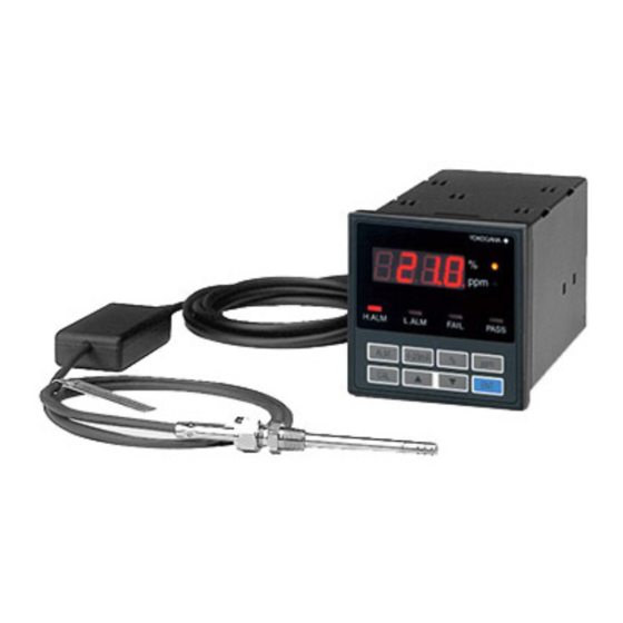
2. System Configuration System Configuration A basic system of the OX102 oxygen analyzer comprises a sensor, extension cable and converter. The length of the extension cable is selectable - any of 4 m, 9 m and 29 m - to accommodate your application. An optional sampling unit (K9424GA) is available to filter out organic solvents, if a sample gas contains such solvents at a level between a few ppm and a few percent, such as in reflow applications. -
Page 22: System Configuration 2
2.2 System Configuration 2 This configuration, incorporating an optional sampling unit to remove organic solvents, should be used when a sample gas contains such solvents at a level of a few ppm to a few percent. Sensor Sampling Unit (K9424GA) Heater Control Kit Converter... -
Page 23: Installation
3. Installation Installation This chapter explains installation procedures for components of the OX102 oxygen analyzer. 3.1 Installing the Sensor (1) Installation Site The OX102 should be installed in a place where there is adequate space for inspection and maintenance. For calibration, the sensor should be removed from the process and installed in the calibration kit. - Page 24 WARNING • Sensor cable should be within 30 cm of sensor housing, and angle of bend (see figure below) should not be greater than 60 . • When mounting sensor through a 17 mm hole, mounting plate should be no greater than 4 mm thick.
-
Page 25: Installing The Converter
3. Installation 3.2 Installing the Converter (1) Installation Site The converter should be installed in places where: • Easy access to display and key operations can be achieved. • Inspection and maintenance can be easily performed. • Ambient temperature does not exceed 50 C and temperature fluctuations are minimal: Avoid exposure to direct sunlight or radiant heat. -
Page 26: Installing The Optional Sampling Unit (K9424Ga)
3.3 Installing the Optional Sampling Unit (K9424GA) The sampling unit is a desktop type and should be installed on a stand near the sampling point. Note the following when installing the unit. Notes The unit should be installed in places where: •... -
Page 27: Wiring
4. Wiring Wiring This chapter explains the procedures for wiring the converter. 4.1 Precautions Notes Do not apply power to the converter or any other devices, such as alarm devices, relating to the power circuit of the converter, until all wiring has been completed. 4.2 Wiring Types The converter requires the following wiring. -
Page 28: Terminals For External Connections
4.3 Terminals for External Connections External connections should be made from the terminals on the rear side of the con- verter. Be careful not to make any mistakes. 4-20 1-5V 100- FAIL SNSR F401.EPS Figure 4.1 Terminal Configuration CAUTION • When wiring, ensure that the mains power supply is disconnected, to minimize the risk of electric shock. -
Page 29: Wiring Procedures
4. Wiring 4.4 Wiring Procedures Follow the instructions below for wiring the converter. (1) Sensor wiring Sensor is connected using a special extension cable with 15P connector. Plug in the connector and tighten the screws to secure it. (2) Signal output There are two types for signal output: 4-20 mA DC and 1-5 V DC. - Page 30 (5) Fail Contact Signal This contact output is a relay contact, and closes when a failure condition exists, such as disconnection of the sensor heater, and failure or disconnection of cable between the sensor and the converter. Use 600 V-rated vinyl insulated wires (JIS C3307), or wires or cables of equivalent or greater capacity, for connections as shown in Figure 4.4.
-
Page 31: Component Functions
5. Component Functions Component Functions This chapter describes functions of main equipment of the OX102 oxygen analyzer. Sensor The sensor uses a zirconia current limiting system, enabling direct insertion of the sensor at elevated temperatures up to 150 C. 0 to 250 C within 50 mm of sensor tip. The sensor should be used at a measuring point pressure of 1013 40 hPa abs. -
Page 32: Converter
5.2 Converter The converter provides oxygen concentration readings based on the signals from the sensor and outputs a 4-20 mA/1-5 V DC signal outside. Also the converter has various functions, including the high/low alarm contact output, easy, one-touch calibration, and self-diagnosis function. -
Page 33: Sampling Unit (Optional)
5. Component Functions 5.3 Sampling Unit (Optional) The sampling unit comprises membrane filters, suction pump, flowmeter and activated carbon filter to absorb organic solvents. When a sample gas contains organic solvents, use this sampling unit to filter out such solvents. The expected life of the activated carbon filter is approximately 50 hours when a sample gas contains 500 ppm of isopro- pyl alcohol and flows at 500 ml/min. -
Page 34: Calibration Kit (Optional)
The shelf life of a calibration gas shall be one year from the manufacturing date speci- fied on the label of the cylinder. Yokogawa shall not guarantee accuracy of the equip- ment, if it is calibrated with an expired calibration gas. -
Page 35: Operation
6. Operation Operation This chapter explains how to operate the OX102 oxygen analyzer. 6.1 Startup The startup procedure is outlined in the following chart. Checking wiring and piping See Section 6.1 (1) Checking gas flow rate, when using sampling unit See Section 6.1 (2) See Section 6.1 (3) Applying power to converter... - Page 36 (4) Operating procedure for the calibration gas kit 1. Pull the needle tip up inside the gasket to Needle tip Valve the position shown in Figure 1. 2. Screw the valve onto the mouth of a container with the fingers until it meets resistance and then screw the locknut down.
-
Page 37: Operational Flow Chart
6. Operation 6.2 Operational Flow Chart The following definitions apply in general to the notation used in the text to express and explain the operation keys and the display descriptions. Refer to Figure 5.2 for the functions of the operation keys and the indications on the converter front panel. Notation descriptions for the operational flow chart (1) Display Notation... - Page 38 Operational Flow Chart Measurement mode Press [ppm + CAL] to return to measurement mode Measured Value Press [ALM] for setting alarm setting For readings in percentage, the % lamp is ON and the ppm lamp is OFF. "HI.AL" is displayed to prompt setting entry High Alarm Press [ENT] to enter setting entry, or press [ALM] to skip...
-
Page 39: Configuring Data
6. Operation 6.3 Configuring Data (1) Configuring the sensor parameters Upon replacing sensors, parameters must be configured following the chart below. Parameters to be configured are specified in the Sensor Parameter Table (Figure 5.1) attached on a new sensor. Indication Operational Flow Chart Measured Value... - Page 40 Continued To measurement mode GIN.2 ppm+CAL Gain 2 A Value Gain 2 A Value ppm+CAL Value Changing accepted value Gain 2 B Value ppm+CAL Value Changing accepted value To be continued (to GIN.3) F6302.EPS IM 11M10A01-03E...
- Page 41 6. Operation Continued To measurement mode GIN.3 ppm+CAL Gain 3 A Value ppm+CAL Value Changing accepted value Gain 3 B Value ppm+CAL Value Changing accepted value To be continued (to GIN.4) F6303E.EPS IM 11M10A01-03E...
- Page 42 Continued To measurement mode GIN.4 ppm+CAL Gain 4 A Value ppm+CAL Value Changing accepted value Gain 4 B Value ppm+CAL Value Changing accepted value To be continued (to GIN.5) F6304E.EPS IM 11M10A01-03E...
- Page 43 6. Operation To measurement mode Continued GIN.5 ppm +CAL Gain 5 A Value ppm+CAL Value Changing accepted value Gain 5 B Value ppm+CAL Value Changing accepted value To be continued (to GIN.6) F6305E.EPS IM 11M10A01-03E...
- Page 44 To measurement mode Continued GIN.6 ppm+CAL All GAIN Value ppm+CAL Gain 6 (Gln. 6) is not user configurable. F6306E.EPS (2) Automatic/Manual Switching In this mode, either automatic or manual range switching can be selected. Set either mode following the procedure shown in the flow chart below. When the autoswitching is selected, the mode of “Configuring the 4-20 mA output signal”...
- Page 45 6. Operation (3) Configuring the 4-20 mA output signal This mode is to configure the 4-20 mA output signal for the fixed range. Configure the signals following the procedure shown in the flow chart below. This mode is automatically determined if the automatic/manual range switching mode is set to autorange mode.
- Page 46 (4) Configuring the 1-5 V output signal This mode is to configure the 1-5 V output signal to correspond to a fixed range. Configure the signals following the procedure shown in the flow chart below. This output signal is always set to correspond to a fixed range. Therefore, even if automatic range switching is selected, this output signal should be configured for each range.
- Page 47 6. Operation (5) Configuring high/low alarm contact output settings This mode is to configure the oxygen concentration high/low alarm contact output settingsalarm. Configure settings following the procedure shown in the flow chart below. The high alarm setting should be equal or greater than the low alarm setting. Indication Operational Flow Chart Measured...
- Page 48 Continued Measurement mode Low alarm L.ALM ppm+CAL Low alarm setting L.ALM ppm+CAL Changing value High Alarm > Low Alarm Value accepted ( ) If the entered high alarm setting is less than the low alarm setting, the display will show E- - - for about 3 seconds and the entered setting will flash to prompt reentry.
- Page 49 6. Operation (7) Key lock This is to lock each key operation. Indication Flow Chart Measured Value Set key lock or releise key lock PASS F6322E.EPS ( ) While the "PASS" lamp is on, the key lock mode is enabled so that key operations are not permitted.
-
Page 50: Calibration
10000 ppm 8500-9500 ppm O gas cylinder (*2) *(1) Or 1000 ppm O calibration gas (1L, P/N K9424JP) T6401E.EPS *(2) Or 10000 ppm O calibration gas (1L, P/N K9424JQ) For complete calibration, contact YOKOGAWA for factory calibration. IM 11M10A01-03E 6-16... - Page 51 6. Operation [Air Calibration] Indication Operational Flow Chart Measured Value CAL1 is for 0-25% O range calibration. When using dry air as calibration gas, enter 20.9 using Supplying calibration gas No.1 keys concentration in the range: 15-25%) CAL.1 ppm+CAL Air O value ppm+CAL Entering calibration value...
- Page 52 Continued from CAL.1 Measurement Mode [100 ppm O Calibration] Indication Stop supplying calibration gas No.1 (*) CAL2 is for 0-100 ppm range calibration. CAL.2 Assuming the O Supplying calibration gas No.3 concentration in the range: 80-120 ppm) concentration of calibration gas is 110 ppm, enter this value using keys.
- Page 53 6. Operation Continued from CAL.2 Measurement Mode Indication [1000 ppm O Calibration] Stop supplying calibration gas No.3 CAL.3 ( ) CAL3 is for 0-1000 ppm Supplying calibration gas No.5 (O range calibration. concentration allowance: 900-1100 ppm) Assuming the O concentration of calibration gas is 995 ppm, enter this value using ppm+CAL...
- Page 54 Measurement Mode Continued from CAL.3 [10000 ppm O Calibration] Indication Stop supplying calibration gas No.5 ( ) CAL4 is for 0-10000 ppm CAL.4 Supplying calibration gas No.6 (O concentration range calibration. Assuming allowance: 8500-9500 ppm) the O concentration of calibration gas is 9310 ppm, enter this value using keys.
- Page 55 6. Operation The procedure for complete calibration, requiring six types of calibration gas, is illustrated in the following flow chart. Continued from CAL.4 Measurement Mode [Air Calibration] Indication CAL.5 ( ) Calibration using air. Supplying calibration gas No.1 (O When using dry air as concentration allowance: 15-25%) calibration gas, enter 20.9 using...
- Page 56 [20 ppm O Calibration] Indication Continued Measurement mode Stop supplying calibration gas No.1 and supply No.2 (O concentration allowance: 15-25 ppm) ppm+CAL Entering calibration value Calibration value Calibration ppm + CAL completed Measured value Changing Calculating value Calibration completed ERROR [100 ppm O Calibration] Waiting for 100 ppm calibration...
- Page 57 6. Operation Stop supplying calibration gas No.3 and [500 ppm calibration] Indication supply No.4 concentration allowance: 400-600 ppm) Measurement mode ppm+CAL Entering calibration value Calibration value ppm + CAL Measured value Changing Calculating value Calibration ERROR completed Waiting for 1000 ppm calibration [1000 ppm calibration] 1000 Stop supplying calibration gas No.4 and...
- Page 58 [10000 ppm O Calibration] Indication Stop supplying calibration gas No.5 and supply No.6 10000 concentration allowance: 8500-9500 ppm) Measurement mode ppm+CAL Entering calibration value Calibration value ppm + CAL Measured value Changing Calculating value Calibration ERROR completed Note: To return to measurement mode, press [ppm + CAL] F6319E.EPS (2) Moving zero point This is to translate the output function: to change value b of the characteristic function, y...
-
Page 59: Inspection And Maintenance
This chapter explains inspections to ensure best performance and operations of the OX102 oxygen analyzer. If repair is required, this equipment will need to be returned to the factory. Contact your Yokogawa representative. 7.1 Sensor NOTE • Do not touch the sensor head accidentally while the sensor is hot right after removing it from the process. - Page 60 (2) Replacement interval for the disk filter (P/N K9424GQ) varies depending on dust content in the sample gas. Check the cleanness of element to determine the filter replacement cycle. The felt filter (P/N K9346WH) is for preventing the activated carbon from leaking so it requires no replacement unless abnormal conditions occur. (3) Increasing contamination of the filter may deteriorate the flow rate of sucked sample gas.
-
Page 61: Troubleshooting
4. Useful life of activated charcoal filter is over 4. Replace activated charcoal filter No alarm contact signal is 1. Alarm contact signal is not set 1. Set the alarm contact signal properly activated1. 2. Alarm contact relay failure 2. Contact Yokogawa T801E.EPS IM 11M10A01-03E... -
Page 63: Appendix 1. Sampling Unit
Notes If repair is required, the is equipment will need to be returned to the factory. For repair or maintenance, contact your Yokogawa representative. 1. Specifications Pressure at sampling point : Atmospheric pressure... -
Page 64: Installation
2. Installation The sampling unit is a desktop type and should be installed on a stand near the sampling point. Note the following when installing the unit. NOTE The unit should be installed in places where: • Ambient temperature is in the range of 0 to 40 C and temperature fluctuations are minimal. -
Page 65: Operating Procedures
Appendix 3. Operating Procedures 3.1 Starting operation Before starting the operation of the sampling unit, make sure to power down the OX100 Series oxygen analyzers. Take the following steps to start operating the unit. (1) Mount an OX100 Series sensor to the sensor connector of the sampling unit by inserting 70 to 80 mm of the sensor and tightening the locknut firmly with fingers. -
Page 66: Maintenance
4. Maintenance When this sampling unit is used with OX100 serise Oxygen Analyzer, if the sampling unit is not properly maintained the life of the Oxygen Analyzer sensor will be adversely affected, drift will occur or the instrument will not calibrate. Frequent filter maintenance is particularly important. -
Page 67: Appendix 2. Calibration Gas Kits
Appendix Appendix 2. Calibration Gas Kits K9424JA, K9424JB, K9424JR, K9424JS Calibration Gas Kits for OX100/102 The calibration gas kits are designed for calibration of the OX100 Series Oxygen Analyzers. The kit comprises a calibration gas (filled pressure of 0.7 MPa, 6 one-litter cylinders) and a needle valve assembly. -
Page 68: Supplying The Calibration Gas
2. Supplying the calibration gas Take the following steps to supply the calibration gas. (1) Mount an OX100 Series sensor to the needle valve assembly by inserting 70 to 80 mm of the sensor and screwing down the locknut firmly with fingers. The locknut should be finger tight only and do not use a wrench for tightening. -
Page 69: Customer Maintenance Parts List
Sensor Sensor Cable K9424LB Cable (4m) K9424LC Cable (9m) Cable (29m) K9424LD CMPL 11M10A01-03E All Rights Reserved, Copyright © 2000, Yokogawa Electric Corporation. Subject to change without notice. 1st Edition : Apr. 2000 (YK) 5th Edition : Nov. 2007 (YK) - Page 70 A1109EF Disk Filter K9424GQ 1: Comprises a stainless steel case (including an activated carbon filter and a disk filter) and a spere activated carbon element. CMPL 11M10A01-03E All Rights Reserved, Copyright © 2000, Yokogawa Electric Corporation. 5th Edition :Nov. 2007...
- Page 71 K9424JC NEEDLE VALVE ASSY Description Item Part No. Needle Valve Assy K9424JD K9424HQ Regulator CMPL 11M10A01-03E 5th Edition : Nov. 2007 All Rights Reserved, Copyright © 2000, Yokogawa Electric Corporation.
-
Page 73: Revision Record
Revision Record Manual Title : Model OX102 Current Limit type Oxygen Analyzer Manual Number : IM 11M10A01-03E Edition Date Remark (s) Dec. 2000 Newly published Nov. 2002 Shown Belew Added caution about requirement for return of equipment to factory for repaia. 1.1 Added conditions requiring sampling unit to specification.