Table of Contents
Advertisement
Quick Links
Advertisement
Table of Contents

Related Manuals for Zte H3140


Summary of Contents for Zte H3140
- Page 1 H3140 Home Gateway Maintenance Management Guide Version:V1.0 ZTE CORPORATION ZTE Plaza, Keji Road South, Hi-Tech Industrial Park, Nanshan District, Shenzhen, P.R.China Postcode: 518057 Tel: +86-755-26771900 URL: http://support.zte.com.cn E-mail: support@zte.com.cn...
- Page 2 If third-party embedded software such as Oracle, Sybase/SAP, Veritas, Microsoft, VMware, and Redhat is delivered together with this product of ZTE, the embedded software must be used as only a component of this product. If this product is discarded, the licenses for the embedded software must be void either and must not be transferred.
-
Page 3: Table Of Contents
Contents 1 Safety Precautions..................1 2 Product Overview..................4 2.1 Package Check......................4 2.2 Product Specifications....................4 2.3 Hardware Description....................5 2.4 Hardware Connection.....................10 3 Configuration Preparation................. 12 3.1 Configure the IP Address of the Computer............12 3.2 Login........................13 4 Configure the Internet................15 4.1 Check the Status....................15 4.1.1 Check the Ethernet Status................ - Page 4 5.1 Check the Local Network Status................42 5.2 Configure the WLAN....................43 5.2.1 Configure the Basic Parameters of the WLAN..........43 5.2.2 Configure the Advanced Parameters of the WLAN........46 5.2.3 Configure the BSS Steering..............48 5.2.4 Configure the Wi-Fi Scheduler..............48 5.3 Configure the LAN....................49 5.3.1 Configure the LAN(IPv4)................
- Page 5 7.8 Network Diagnosis....................86 7.9 Check the ARP Table.................... 88 7.10 Check the MAC Table..................88 7.11 Configure the IPv6 Switch..................89 7.12 Configure the Ethernet WAN................90 8 Troubleshooting..................91...
-
Page 7: Safety Precautions
Chapter 1 Safety Precautions Note Before using the device, read the following safety precautions. ZTE bears no liability to the consequences incurred by violation of the safety instructions. Usage Cautions Read all the safety cautions carefully before using the device. - Page 8 EU Declaration of Conformity Hereby, ZTE Corporation declares that the radio equipment type H3140 is in compliance with Directive 2014/53/EU, The full text of the EU declaration of conformity is available at the following Internet address: http://support.zte.com.cn/support/cer/EU...
- Page 9 1 Safety Precautions Environmental Information The equipment you purchased has required the extraction and use of natural resources for its production. It may contain substances that are hazardous to people’s health and to the environment. To avoid putting such substances into our environment and to re- duce pressure on our natural resources, we ask that you reuse or recycle your end-of- life equipment by using an accredited electronics take-back system.
-
Page 10: Product Overview
Keep the package and all the items in good condition if you want to replace the product. 2.2 Product Specifications The H3140 product is a new generation home gateway device with 802.11AX Wi-Fi (2.4GHz, 5GHz), which provides High Speed Internet, IPTV and Voice over IP services through the GE or Fiber(SFP) uplink. -
Page 11: Hardware Description
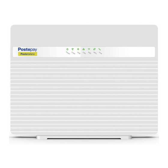
EIRP < 30 dBm (5470 – 5725) MHz Note Please use the power adapter provided by the manufacturer. 2.3 Hardware Description Front panel Figure 2-1 shows the front panel of the H3140, and Figure 2-2 shows the indicators. SJ-20210621164956-009 | 2021-12-07(R1.0) - Page 12 H3140 Maintenance Management Guide Figure 2-1 The Front Panel Figure 2-2 The indicators Indicator Status Description Power Fixed green All services are available. At lease one wireless radio is enabled. Fixed red One or more subscription services are currently unavail- able.
- Page 13 The VoIP telephone service is active and there are activi- ties in progress. The VoIP telephone service is not active or is not included in your subscription. Side panel Figure 2-3 shows the interfaces on the side panel of the H3140. SJ-20210621164956-009 | 2021-12-07(R1.0)
- Page 14 Figure 2-3 The Side Panel Interface Function USB1 USB 3.0 host port, it is used to connect to the USB storage device. Rear panel Figure 2-4 shows the interfaces and buttons on the rear panel of the H3140. SJ-20210621164956-009 | 2021-12-07(R1.0)
- Page 15 2 Product Overview Figure 2-4 The Rear Panel Interface/Button Function WiFi WLAN switch , it is used to turn on / off the WLAN. WPS Push Button. Reset During power ON period, hold on this button for more than 5 seconds to reset the current settings to the factory default setting, and then the sys- tem restarts automatically.
-
Page 16: Hardware Connection
H3140. Figure 2-5 Cable Connection After the devices are connected to the H3140 device, press the power button. When the corresponding indicators on the front panel are On, you can enjoy various services pro- vided by the service provider. - Page 17 2 Product Overview The product should be installed on the same floor as the applied area. Do not put other objects on the product. Try to reduce the number of obstacles be- tween the product and a wireless terminal. Horizontally place the product in the middle of the applied area and do not put it in a ...
-
Page 18: Configuration Preparation
3.1 Configure the IP Address of the Computer Abstract To log in to the H3140 on a computer, you need to set the IP address of the computer to ensure that the IP address of the computer and the maintenance IP address of the H3140 are in the same network segment. -
Page 19: Login
The H3140 provides a Web-based configuration and management system. You can en- ter a specified IP address in the address bar of Internet explorer to access the system. Prerequisite A computer is directly connected to the H3140, and their IP addresses are in the same network segment. Steps 1. - Page 20 H3140 Maintenance Management Guide Figure 3-1 Login Page 2. Enter the username and password, and click Login. The configuration page is dis- played, see Figure 3-2. Figure 3-2 Configuration Page SJ-20210621164956-009 | 2021-12-07(R1.0)
-
Page 21: Configure The Internet
The section describes how to check the Ethernet status. Steps Check Ethernet Interface Information 1. On the main page of the H3140, select Internet > Status > SFP/Ethernet > SFP/ Ethernet Interface Information to the SFP/Ethernet Interface Information page, Figure 4-1. - Page 22 Figure 4-1 SFP/Ethernet Interface Information 2. Click Refresh to refresh the information. Check Ethernet Connection Status 3. On the main page of the H3140, select Internet > Status > Ethernet > Ethernet Connection Information to the Ethernet Connection Information page, see Fig- 4-2.
-
Page 23: Check The 3G Status
The section describes how to check the mobile network and 3G connection status. Steps Check Mobile Network 1. On the main page of the H3140, select Internet > WAN Status > 3G > Mobile Net- work to the Mobile Network page. The signal strength can verify the network card is plugged, see Figure 4-3. - Page 24 H3140 Maintenance Management Guide Steps 1. On the main page of the H3140, select Internet > WAN > SFP/Ethernet to the Eth- ernet Connection page and then click the Create New Item, see Figure 4-5. Figure 4-5 Ethernet Connection page Table 4-1 lists the new item parameters.
- Page 25 Subnet Mask Subnet mask of H3140. Gateway It is usually the IP address of the H3140 by default. IP address of the DNS server for static connections. You can set DNS1-DNS3 up to three IP addresses for the server. These IP addresses are provided by the ISP.
-
Page 26: Configure The 3G
2. Click Apply button to apply the changes. 4.2.2 Configure the 3G Abstract A Dongle device can be connected to H3140 through a USB interface. If the Dongle has a 3G (SIM) card inserted, the H3140 can access the Internet through the Dongle device. Contacts Table 4-2 lists the 3G process of configuring the WAN connection. - Page 27 4-6. Figure 4-6 Mobile Network 3. Click Refresh to refresh the information. 4. On the main page of the H3140, select Internet > WAN > 3G to the 3G Connection page. Table 4-3 lists the New Item parameter. After the setup is complete, you can see the...
-
Page 28: Configure The Qos
H3140 Maintenance Management Guide Figure 4-7 New 3G Connection Table 4-3 New 3G Connection parameters Parameter Description Connection Name Name the 3G connection. PDP Type There are two PDP types: Set the communication standard of the access network to be used. -
Page 29: Configure The Qos Global Parameters
Different packets can also be marked with different flags for chan- nels with different priorities. Steps 1. On the main page of the H3140, select Internet > QoS > Classification to the Clas- sification page. 2. Click to create new QoS classification, see Figure 4-9. - Page 30 H3140 Maintenance Management Guide Figure 4-9 New QoS Classification Page Table 4-4 lists the QoS classification Configuration parameters. Table 4-4 Parameter Descriptions for the QoS Classification Parameter Description On/Off Set radiobox On to enable the function of classification. Name To create a QoS classification, enter the name of the classifica- tion.
-
Page 31: Configure The Security
4 Configure the Internet Parameter Description If setting radiobox Off to disable all Interface, specify the data traf- Ingress fic direction. Source MAC Address Source host MAC address. Destination MAC Address Destination host MAC address. 802.1p Specify the 802.1p value to modify the service priority. VLAN ID Identifies a VLAN. - Page 32 H3140 Maintenance Management Guide Steps Configure the Firewall 1. On the main page of the H3140, select Internet > Security > Firewall to the Fire- wall page, see Figure 4-10. Figure 4-10 Firewall Page 2. Set the parameters. For a description of the parameters, refer to Table 4-5.
-
Page 33: Configure The Filter Criteria
Steps Configure the Filter Switch and Mode Parameters 1. On the main page of the H3140, select Internet > Security > Filter Criteria to the Filter Criteria page. 2. Click Filter Switch and Mode Configuration to the configuration page, see Figure 4-12. - Page 34 H3140 Maintenance Management Guide Figure 4-12 Filter Switch and Mode Configuration Page 3. Configure filter switch and mode configuration parameters, see Table 4-7 Table 4-7 Parameter Descriptions for the Filter Switch and Mode Configuration Parameter Description Filter Set radiobox On to enable the URL filter function.
- Page 35 4 Configure the Internet Configure the IP Filter 8. Click IP Filter to open the IP filter page, see Figure 4-14. Figure 4-14 IP Filter Page Table 4-9 lists the IPv4 filter parameters. Table 4-9 Parameter Descriptions for the IPv4 Filter Parameter Description On/Off...
-
Page 36: Configure The Local Service Control
Steps Configure the Service Control-IPv4 1. On the main page of the H3140, select Internet > Security > Local Service Control to the Local Service Control page. 2. Click Service Control-IPv4 to open Service Control-IPv4 page and then click the... - Page 37 If the Ingress is WAN_All, all the WAN connection can access H3140. If the Ingress is LAN, the LAN side can access H3140. If the Ingress is a WAN or Route_3G connection, the connec- ...
- Page 38 If the Ingress is WAN_All, all the WAN connection can access H3140. If the Ingress is LAN, the LAN side can access H3140. If the Ingress is a WAN or Route_3G connection, the connection selected can access H3140.
-
Page 39: Configure The Alg
IP address, thus improving security. Steps 1. On the main page of the H3140, select Internet > Security > ALG to the ALG page, the page see Figure 4-18. -
Page 40: Configure The Dmz
LAN host provides external services through the translation of destination address DNAT. By default, the system opens all ports. Steps 1. On the main page of the H3140, select Internet > Security > DMZ to the DMZ page, the page see Figure 4-19. - Page 41 URL, in- stead of an IP address. Steps 1. On the main page of the H3140, select Internet > Security > Port Forwarding to the Port Forwarding page,and then click the Create New Item, the page see Figure 4-20.
-
Page 42: Configure The Parental Controls
By creating new parental controls rules, you can effectively control the internet access time of teminals and access websites. Steps 1. On the main page of the H3140, select Internet > Parental Controls to the Parental Controls page and then click the Create New Item, see Figure 4-21. -
Page 43: Configure The Ddns
The server provides the DNS service and implements dynamic domain name resolution. Steps 1. On the main page of the H3140, select Internet > DDNS to the DDNS page, see Fig- 4-22. - Page 44 H3140 Maintenance Management Guide Figure 4-22 DDNS Configuration Page 2. Configure the DDNS parameters. Table 4-16 lists the DDNS parameters. Table 4-16 Parameter Descriptions for the DDNS Parameter Description Provider Supported provider. Options: DynDNS, DtDNS, No-IP, easyDNS, freedns and TZO.
-
Page 45: Configure The Sntp
Set the H3140 clock synchronization server information and time zone information so that the user can see that the system time is consistent with the local time. Steps 1. On the main page of the H3140, select Internet > SNTP to the SNTP page, see Fig- 4-23. -
Page 46: Configure The Mulitcast
Steps 1. On the main page of the H3140, select Internet > Multicast > IGMP to the IGMP page, see Figure 4-24. Figure 4-24 IGMP Configuration Page 2. - Page 47 (also called MLD proxy device) with the MLD proxy function is no longer an IPv6 PIM neighbor, but only a host. Steps 1. On the main page of the H3140, select Internet > Multicast > MLD to the MLD page, see Figure 4-25.
-
Page 48: Configure The Local Network
Local Network status includes LAN Status, WLAN Status, WLAN Client Status, LAN Client Status and USB Storage Status. Steps 1. On the main page of the H3140, select Local Network > Status to the Local Net- work Status page, see Figure 5-1. -
Page 49: Configure The Wlan
Steps Enable or Disable the WLAN Function 1. On the main page of the H3140, select Local Network > WLAN > WLAN Basic to the WLAN Basic page, see Figure 5-2. - Page 50 H3140 Maintenance Management Guide Table 5-1 WLAN On/Off Configuration parameters Parameter Description WLAN (2.4GHz) Click On to enable the 2.4 GHz wireless function. Click Off to disable the 2.4 GHz wireless function. WLAN (5GHz) Click On to enable the 5 GHz wireless function.
- Page 51 5 Configure the Local Network Parameter Description Band Width Radio frequency bandwidth, including Auto,20 Mhz and 40 Mhz. De- fault: Auto. Enable or disable function. Beacon Interval Interval for transmitting beacon frames, default: 100 ms. Beacon frames are used for communicating with other AP devices or network control devices to announce the WLAN presence.
-
Page 52: Configure The Advanced Parameters Of The Wlan
WLAN Advanced provides the parameters of WLAN Advanced configuration features. Steps Access Control-Mode Settings 1. On the main page of the H3140, select Local Network > WLAN > WLAN Advanced to the WLAN Advanced page. 2. Click Access Control-Mode Configuration the configuration page, see Figure 5-5. - Page 53 5 Configure the Local Network Table 5-4 Access Control-Mode configuration parameters Parameter Description No Filter No filter is to be applied (the default). Black List Deny LAN users to access specific address. White List Allow LAN users to access specific address. 4.
-
Page 54: Configure The Bss Steering
5GHz Wi-Fi, and leave the 2.4GHz Wi-Fi less-crowded for those clients who support 2.4GHz only, therefore to improve Wi-Fi performance for all the clients. Steps 1. On the main page of the H3140, select Local Network > WLAN > BSS Steering to the BSS Steering page, see Figure 5-7. -
Page 55: Configure The Lan
The relevant information of Internet status includes Allocated Address(DHCP), DHCP Server and DHCP Binding. Steps Configure Allocated Address(DHCP) 1. On the main page of the H3140, select Local Network > LAN > IPv4 to the IPv4 page. SJ-20210621164956-009 | 2021-12-07(R1.0) - Page 56 H3140 Maintenance Management Guide 2. Click Allocated Address(DHCP) to the configuration, see Figure 5-9. Figure 5-9 Allocated Address(DHCP) Page 3. Click Refresh to refresh the informations. Configure DHCP Server 4. Click DHCP Server to the configuration, see Figure 5-10. Figure 5-10 DHCP Server(IPv4) Page...
- Page 57 5 Configure the Local Network 5. Configure the DHCP server parameters. Table 5-8 lists the DHCP server parameters. Table 5-8 Parameter Descriptions for the DHCP Server Parameter Description Select On to let the device work as a DHCP server and as- DHCP Server sign IP addresses to open the client PCs or wireless de- vices.
-
Page 58: Configure The Lan(Ipv6)
IPv6 WAN connection. Steps Configure Allocated Address(DHCPv6) 1. On the main page of the H3140, select Local Network > LAN > IPv6 to the IPv6 page. 2. Click Allocated Address (DHCPv6) to the configuration page, see Figure 5-12. - Page 59 5 Configure the Local Network Figure 5-13 LAN Address Management Page 5. Configure the LAN address parameters. Table 5-10 lists the LAN address parame- ters. Table 5-10 Parameter Descriptions for the LAN Address Parameter Description LAN IPv6 Address The IPv6 address of LAN. 6.
- Page 60 H3140 Maintenance Management Guide Figure 5-15 DHCPv6 Server Page 11. Configure the DHCPv6 server parameters. Table 5-12 lists the DHCPv6 server parameters. Table 5-12 Parameter Descriptions for the DHCPv6 Server Parameter Description DHCPv6 Server Select On to let the device work as a DHCP server and assign IP addresses to the client PCs or wireless devices.
- Page 61 5 Configure the Local Network Figure 5-16 RA Service Page 14. Configure the service parameters.Table 5-13 lists the RA service parameters. Table 5-13 Parameter Descriptions for the RA Service Parameter Description RA Service Enable or disable the RA service function. Specify MTU If On button is selected, enter the MTU value.
-
Page 62: Configure The Edns0
RFC 1035. eDNS0 Allows the DNS requester to publicize the size of its UDP packets and make it easier to transmit packets larger than 512 bytes. Steps 1. On the main page of the H3140, select Local Network > LAN > eDNS0 to the eD- NS0 page, see Figure 5-17 Figure 5-17 eDNS0 Page 2. - Page 63 5 Configure the Local Network Figure 5-18 Routing Table Page 3. Click Refresh to refresh the information. Configure Static Routing 4. Click Static Routing to the configuration page and then click the Create New Item, Figure 5-19. Figure 5-19 Static Routing Page 5.
- Page 64 H3140 Maintenance Management Guide 7. Click Policy Routing to the configuration page and then click the Create New Item, Figure 5-20. Figure 5-20 Policy Routing Page 8. Configure the policy routing parameters. Table 5-15 lists the policy routing parame- ters.
-
Page 65: Configure The Routing (Ipv6)
Before configuring routing (IPv6), make sure that the IPv6 WAN connection is created. Steps Configure Routing Table 1. On the main page of the H3140, select Local Network > Routing > IPv6 to the Routing (IPv6) page. 2. Click Routing Table to the configuration page, see Figure 5-21. - Page 66 H3140 Maintenance Management Guide Figure 5-22 Static Routing (IPv6) Page 5. Configure the static routing parameters. Table 5-16 lists the static routing parame- ters. Table 5-16 Parameter Descriptions for the Static Routing Parameter Description Name The name of static routing entry.
- Page 67 5 Configure the Local Network Figure 5-23 Policy Routing (IPv6) Page 8. Configure the policy routing parameters. Table 5-17 lists the policy routing parame- ters. Table 5-17 Parameter Descriptions for the Policy Routing Parameter Description Name The name of Policy routing entry. Egress WAN connection for policy routing Source IP Address...
-
Page 68: Configure The Ftp Server Feature
5.5 Configure the FTP Server Feature Abstract This procedure describes how to enable the feature of the H3140 by configuring FTP parameters, including the username and password. Steps 1. In the left navigation tree, click Local Network > FTP. The FTP Application page is... -
Page 69: Configure The Dms
5 Configure the Local Network 1. On the main page of the H3140, select Local Network > UPnP to the UPnP, see Figure 5-25. Figure 5-25 UPnP Page Table 5-19 lists the UPnP parameters. Table 5-19 Parameter Descriptions for the UPnP... - Page 70 H3140 Maintenance Management Guide The version of the Windows media player used for DMS function must be 11 or later, or the OS must be vista or Win 7. To enable the DMP function in OS of earlier version, spe- cial tools, such as Intel(R) Tool for UPnP(TM) Technology or Twonky Media Manager must be installed.
-
Page 71: Configure The Dns
The relevant information of Internet status includes Domain name, Host Name and DNS. Steps Configure the Domain Name 1. On the main page of the H3140, select Local Network > DNS to the Domain Name page, see Figure 5-28. Figure 5-28 Domain Name Page 2. -
Page 72: Configure The Voip
This procedure describes how to check shows the relevant information of VoIP status. Steps 1. On the main page of the H3140, select VoIP > Status. The VoIP Status page is dis- played, see Figure 6-1. Figure 6-1 VoIP Status Page 2. -
Page 73: Configure The Sip Accounts
This procedure describes how to configure basic parameters of the VoIP service, includ- ing sip account, authorization username, password. Steps 1. On the main page of the H3140, select VoIP > Basic. The SIP Account-1 page is displayed, see Figure 6-2. -
Page 74: Configure The Advanced Parameters Of Voip
This procedure describes how to configure advanced parameters of the VoIP service, in- cluding echo cancellation, jitter buffer, and DTMF. Steps Configure the Advanced Parameters 1. On the main page of the H3140, select VoIP > Advanced. The Advanced Parame- ters page is displayed, see Figure 6-3. - Page 75 6 Configure the VoIP 4. On the main page of the H3140, select VoIP > Advanced > Echo Cancellation. The Echo Cancellation page is displayed, see Figure 6-4. Figure 6-4 Echo Cancellation Page 5. Set the advanced parameters. For a description of the parameters, refer to Table 6-3.
-
Page 76: Configure The Sip Protocol
This procedure describes how to configure the SIP Protocol, include the proxy port, proxy server and registrar server, Steps 1. On the main page of the H3140, select VoIP > SIP Protocol. The SIP Protocol page is displayed, see Figure 6-6. -
Page 77: Configure The Media
6 Configure the VoIP Table 6-5 Parameter Descriptions for the SIP Protocol Parameter Description Local Port Local port that the SIP protocol uses, default: 5060. Primary Proxy Server IP address of the active SIP proxy server that the ISP provides, which must be the same as that configured on the SIP server. -
Page 78: Configure The Fax
The H3140 supports the T30 protocol , T38 protocol and V152 protocol fax feature. By default, the T38 protocol is used. Steps 1. On the main page of the H3140, select VoIP > Fax. The Fax page is displayed, see Figure 6-8. -
Page 79: Configure The Digit Map
Abstract A digital map defines dialing rules that must be followed when you dial a number. Steps 1. On the main page of the H3140, select VoIP > Voice Ports Mapping. The Voice Ports Mapping page is displayed, see Figure 6-9. - Page 80 H3140 Maintenance Management Guide Steps 1. On the main page of the H3140, select VoIP > POS. The POS page is displayed, see Figure 6-10. Figure 6-10 POS Page 2. Set the parameters. For a description of the parameters, refer to Table 6-9.
-
Page 81: Configure The Management And Diagnosis
Configure the Ethernet WAN..................90 7.1 Check the Device Status Abstract The relevant information of device status is shown as below. Steps 1. On the main page of the H3140, select Management&Diagnosis > Status to the Status page, see Figure 7-1. SJ-20210621164956-009 | 2021-12-07(R1.0) -
Page 82: Configure The Account Management
7.2 Configure the Account Management Abstract This procedure introduces how to manage the user accounts and rights. Steps 1. On the main page of the H3140, select Management&Diagnosis > Account Man- agement to the Admin Account Management page, see Figure 7-2. -
Page 83: Configure The Login Timeout
7.3 Configure the Login Timeout Abstract This procedure introduces how to configure the login timeout. Steps 1. On the main page of the H3140, select Management&Diagnosis > Idle Timeout to the Idle Timeout page, see Figure 7-3. Figure 7-3 Idle Timeout Configuration Page 2. -
Page 84: Upgrade Software
This procedure introduces how to upgrade Software. Prerequisite Before upgrading software, make sure that the upgrade file is ready. Steps 1. On the main page of the H3140, select Management&Diagnosis > System Man- agement > Software Upgrade to the Software Upgrade page, see Figure 7-5. -
Page 85: Configure The User Configuration Management
Otherwise, the device may be damaged. Generally, the software is upgraded by the ZTE CORPORATION engineers. If the user wants to upgrade the Firmware, contact the local office of ZTE CORPORATION to obtain the latest Firmware version. -
Page 86: Configure The Mirror Function
If the mirror configuration is performed, the packets at the WAN side will be copied to the specified LAN interface, and it can be used for the network analysis and troubleshooting. Steps 1. On the main page of the H3140, select Management&Diagnosis > Mirror Configu- ration to the Mirror Configuration page, see Figure 7-7. -
Page 87: Configure The Tr069 Function
TR069 configuration features. The relevant TR-069 includes Basic Configuration and Certificate Management. Steps 1. On the main page of the H3140, select Management&Diagnosis > TR-069 to the TR-069 page. 2. Click Basic Configuration to the TR069 basic configuration page, see Figure 7-8. - Page 88 Description ACS URL The URL of the automatic configuration server that manages the device. Username/Pass- User name and password for the H3140 to log in to the automatic configu- word ration server. Connection Re- Connection request URL, which is automatically generated by the system.
-
Page 89: Manage The Log
This procedure introduces how to manage the log. Steps Manage the Log Level 1. On the main page of the H3140, select Management&Diagnosis > Log Manage- ment to the Log Management page. 2. Click Log Level Management to the log level management page, see Figure 7-10. - Page 90 H3140 Maintenance Management Guide Parameter Description Warning Error Critical Alert Emergency The system stores only the logs of the selected level and above levels. 4. Click Apply button to apply the changes. Enable or Disable the System Log Function 5.
- Page 91 7 Configure the Management and Diagnosis 11. Click Security Log Management to the security log management page, see Figure 7-12. Figure 7-12 Security Log Management Page 12. Configure the security log management parameters. Table 7-6 lists the security log management parameters. Table 7-6 Parameter Descriptions for the security Log Management Parameter Description...
-
Page 92: Network Diagnosis
The relevant information includes ping diagnosis and trace route diagnosis. Steps Ping Diagnosis 1. On the main page of the H3140, select Management&Diagnosis > Diagnosis to the Diagnosis page. 2. Click to open Ping Diagnosis page, see Figure 7-14. - Page 93 7 Configure the Management and Diagnosis Table 7-8 Ping Diagnosis Parameter Descriptions Parameter Description IP Address or Host Name Destination IP address or host name. Egress Data direction. If you want to detect the connection with an external address, select a WAN connection. 4.
-
Page 94: Check The Arp Table
7.9 Check the ARP Table Abstract The relevant information of table is shown as below. Steps 1. On the main page of the H3140, select Management&Diagnosis > ARP Table to the ARP Table page, see Figure 7-16. Figure 7-16 ARP Table Page 2. -
Page 95: Configure The Ipv6 Switch
7 Configure the Management and Diagnosis Steps 1. On the main page of the H3140, select Management&Diagnosis > MAC Table to the MAC Table page, see Figure 7-17. Figure 7-17 MAC Table Page 2. Click Refresh button to refresh information. -
Page 96: Configure The Ethernet Wan
7.12 Configure the Ethernet WAN Abstract This page will help you convert LAN to WAN interface. Steps 1. On the main page of the H3140, select Management&Diagnosis > Ethernet WAN to the Ethernet WAN page, see Figure 7-19. Figure 7-19 Ethernet WAN Page 2. -
Page 97: Troubleshooting
Chapter 8 Troubleshooting The Power indicator on the front panel is off after the power button is pressed. The power adapter is not correctly connected to the device. Be sure to use the power adapter supplied with the device. The Linea indicator on the front panel is off after the device is powered on. The WAN link is not established.