Table of Contents
Advertisement
Advertisement
Table of Contents

Related Manuals for AGFA ADC Solo


Summary of Contents for AGFA ADC Solo
- Page 1 ADC Solo User manual...
- Page 2 No parts of this document may be reproduced, copied, adapted or transmitted in any form or by any means without the written permission of Agfa-Gevaert N.V. Agfa-Gevaert N.V. makes no warranties or representation, expressed or implied, with respect to the accu- racy, completeness or usefulness of the information contained in this document and specifically disclaims warranties of suitability for any particular purpose.
-
Page 3: Table Of Contents
....................7 Safety compliance....................8 Operating modes ....................9 Configurations....................... 10 The user interface ....................12 Switching on the ADC Solo ................... 19 Switching off the ADC Solo ................... 21 Chapter 2: Basic operation (‘Operator mode’) ............. 23 Workflow ....................... 24 Reading an image plate .................. - Page 4 2301D EN 20040224...
-
Page 5: Chapter 1: Introducing The Adc Solo
Introducing the ADC Solo This chapter draws attention to important safety precautions and introduces the ADC Solo. ADC Solo features Safety precautions Safety compliance Operating modes Configurations The user interface Switching on the ADC Solo Switching off the ADC Solo... -
Page 6: Adc Solo Features
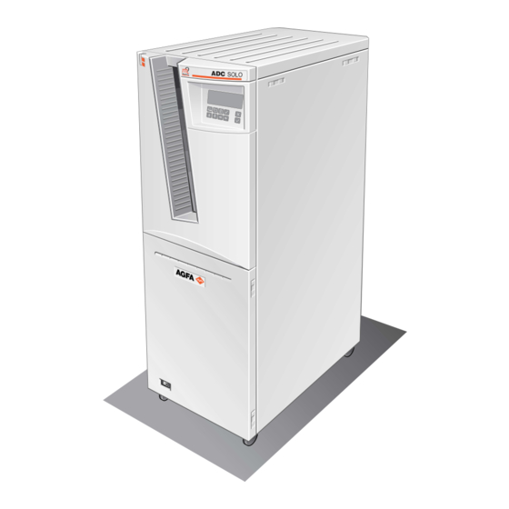
ADC Solo features The ADC Solo is a Digitizer for image plates retaining latent X-ray images. It has been developed by Agfa. The ADC Solo accepts one cassette containing one image plate at a time. The ADC Solo: • takes the cassette containing the image plate from the cassette slot;... -
Page 7: Safety Precautions
ADC Solo from the mains before making repairs or performing any maintenance activities during which live electrical components may be exposed. • As is the case for all technical devices, the ADC Solo must be operated, cared for and serviced correctly. -
Page 8: Safety Compliance
Safety instructions for laser products The ADC Solo is a Class 1 Laser Product. Under normal operating conditions - when the service doors are closed - there can be no laser radiation outside the ADC Solo. • Open the lower front door only to replace the erasure lamps or the fuses. Open the right side panel only to solve cassette or image plate jams. -
Page 9: Operating Modes
Operating modes The ADC Solo can be operated in three modes: operator mode, key-operator mode, and service mode. Operator mode The operator mode groups all basic functions which are aimed at radiographers: • Reading an image plate; • Reading an emergency image plate;... -
Page 10: Configurations
Configurations The ADC Solo can be used in two configurations: either one or more ID Stations serve a range of Digitizers, or one ID Station is dedicated to one Digitizer. The ID Software installed on the ID Station is slightly different depending on the con- figuration. - Page 11 ADC Solo ID Station without ID Tablet Dedicated configuration In the dedicated configuration, you can still use the ADC Solo to digitize cas- settes which have been identified on other ID Stations. 2301D EN 20040224...
-
Page 12: The User Interface
An overview of the functions of the key-operator mode is given in ‘Survey of advanced functions (‘Key-operator mode’)’ on page 48. For detailed information on the key-operator mode, refer to the ADC Solo Reference manual. The ADC Solo interfaces with the user via: • a keypad and a display;... - Page 13 The keypad The ADC Solo keypad features the following keys: To give an image the status ‘emergency’ when it is Emergency sent to the image processing station. This key can only be used for cassettes with ID data. To erase images without digitizing them.
- Page 14 • To move the cursor to the previous entry field. Up key • To scroll upwards. • To increment the number in a numeric entry field. • To move the cursor to the next entry field. Down key • To scroll downwards. •...
- Page 15 The display The ADC Solo control panel has a backlit LCD display with 8 lines of 40 charac- ters each. Its lay-out depends on the operating mode. In operator mode, the display has dedicated areas for specific information: Set-up STATUS...
- Page 16 During transmittal of image data to image processing station. The operator main screen is: READY ADC SOLO When the ADC Solo is treating an image plate, it displays the following screen: BUSY Miller Chest AP In key-operator mode, operation is menu driven. The menu displays the key- operator functions, the active keys, and the service code.
- Page 17 The status indicator The light at the top of the ADC Solo indicates the status of the ADC Solo. Constant/ Color Status Action Flashing Ready. Proceed. Constant Green Busy (treating image Flashing Wait. plate). • Check display for messages. Constant Error.
- Page 18 • A short beep means that ADC Solo has accepted the key command and is start- ing the operation. • A long beep means that you have pressed a non-active key or that the ADC Solo has rejected the key command.
-
Page 19: Switching On The Adc Solo
Switching on the ADC Solo Make sure that the setting of the voltage selector at the back of the machine matches the power supply voltage. 230-240 Locate the main switch and place it in position ‘I’. 2301D EN 20040224... - Page 20 WAIT Self test proceeding During the self-test, you cannot activate any functions. If the ADC Solo has completed the self-test successfully, the ADC Solo enters the operator mode and displays the operator main screen: READY ADC SOLO If the ADC Solo displays:...
-
Page 21: Switching Off The Adc Solo
Switching off the ADC Solo Before switching off Check that the ADC Solo is not scanning an image plate. If the ADC Solo is scanning an image plate, the status indicator at the top of the machine is green and flashing. - Page 22 2301D EN 20040224...
-
Page 23: Chapter 2: Basic Operation ('Operator Mode')
Chapter Basic operation (‘Operator mode’) This chapter provides basic information on how to digitize image plates under normal conditions and in emergency situations. It also treats how to re-erase an image plate to prevent ghost images caused by previous exposures or by stray radiation. -
Page 24: Workflow
31. In the dedicated configuration the identification data are transmitted from the ID Station to the dedicated ADC Solo via the network. Therefore, the ADC Solo can digitize the image plate while you are entering the identification data on the ID Station. -
Page 25: Reading An Image Plate
Status field ADC SOLO • the status indicator at the top of the ADC Solo must be green and be lit constantly. The ADC Solo is operational if the status field equals ‘READY’, even if status messages of the destination are shown (e.g. ‘VIPS not ready’). - Page 26 • returns the cassette; • transmits the digital image data to the image processing station (‘destination’). When the ADC Solo has treated the cassette, it displays the operator main screen. If the ADC Solo displays an error message, refer to ‘Troubleshooting check-...
- Page 27 Remove the cassette from the cassette slot. When the ADC Solo returns the cassette, it is ready to be re-used immedi- ately. However, if you leave it for more than 3 days before re-using it, you must re-erase it first. Refer to ‘Re-erasing an image plate’...
- Page 28 Status field ADC SOLO • the status indicator at the top of the ADC Solo must be green and be lit constantly. The ADC Solo is operational if the status field equals ‘READY’, even if status messages of the destination are shown (e.g. ‘VIPS not ready’).
- Page 29 Make sure to insert the cassette with the hinge [1] at the top and the locking mecha- nism [2] at the bottom. The ADC Solo starts digitizing the image plate. You can enter the identification data, refer to step 4.
- Page 30 100 lines. For more information, refer to the User manual of the ADC Preview Soft- ware. As soon as the ADC Solo has digitized the entire image plate and you have entered the identification data: • the ADC Solo erases the image plate and re-inserts it into the cassette;...
-
Page 31: Reading An Emergency Image Plate
Status field ADC SOLO • the status indicator at the top of the ADC Solo must be green and be lit constantly. The ADC Solo is operational if the status field equals ‘READY’, even if status messages of the destination are shown (e.g. ‘VIPS not ready’). - Page 32 If you do not enter a cassette within 1 minute after pressing the Emergency key or if you enter a cassette without ID data, the ADC Solo will quit the emergency function and return to the operator main screen.
- Page 33 READY ADC SOLO • the status indicator at the top of the ADC Solo must be green and be lit constantly. The ADC Solo is operational if the status field equals ‘READY’, even if status messages of the destination are shown (e.g. ‘VIPS not ready’).
- Page 34 The image plate will be digitized using the speed class, i.e. the sensitivity, corre- sponding to the emergency button as defined during configuration. When the ADC Solo has treated the emergency image plate, it displays the operator digital image data main screen.
- Page 35 Status field ADC SOLO • the status indicator at the top of the ADC Solo must be green and be lit constantly. The ADC Solo is operational if the status field equals ‘READY’, even if status messages of the destination are shown (e.g. ‘VIPS not ready’).
- Page 36 Make sure to insert the cassette with the hinge [1] at the top and the locking mecha- nism [2] at the bottom. The ADC Solo starts digitizing the image plate. While treating the image plate, the ADC Solo will display the following screen: BUSY DIRECT ID...
- Page 37 [Examination type] equals ‘Extremities‘. • If you pressed the emergency button for digitizing images of the trunk, [Examination type] equals ‘Corpus’. When the ADC Solo has treated the emergency image plate, it displays the operator digital image data main screen. The are transmitted to the image processing station accompanied by default ID data.
-
Page 38: Re-Erasing An Image Plate
• the ADC Solo must display the operator main screen with ‘Ready’ status, e.g.: Status READY ADC SOLO • the status indicator at the top of the ADC Solo must be green and be lit constantly. Press the Erase key on the keypad. 2301D EN 20040224... - Page 39 Insert the cassette into the cassette slot. While erasing, the ADC Solo will still display the above screen. When the ADC Solo has erased the image plate, it displays the operator main screen. Warning If the above screen is not displayed but the display reads:...
- Page 40 WARNING The next cassette will be erased Put cassette in slot or press to quit When the ADC Solo has erased the image plate, it displays the operator main screen. Remove the cassette from the cassette slot. 2301D EN 20040224...
- Page 41 READY Status ADC SOLO • the status indicator at the top of the ADC Solo must be green and be lit constantly. Insert the cassette into the cassette slot. The ADC Solo will automatically erase the image plate. The display will read:...
-
Page 42: Reading The Identification Data Of A Cassette (Dedicated Configuration Only)
Status field ADC SOLO • the status indicator at the top of the ADC Solo must be green and be lit constantly. The ADC Solo is operational if the status field equals ‘READY’, even if status messages of the destination are shown (e.g. ‘VIPS not ready’). - Page 43 Make sure to insert the cassette with the hinge [1] at the top and the locking mecha- nism [2] at the bottom. While the ADC Solo reads the identification data from the cassette chip, the status indicator at the top of the machine is red and flashing.
-
Page 44: Changing The Image Plate Type (Dedicated Configuration Only)
Status field ADC SOLO • the status indicator at the top of the ADC Solo must be green and be lit constantly. The ADC Solo is operational if the status field equals ‘READY’, even if status messages of the destination are shown (e.g. ‘VIPS not ready’). - Page 45 Enter the initialization code in the ID Software. Refer to the User manual of the ID Software. While the ADC Solo the initializes the cassette, the status indicator at the top of the machine is red and flashing. When the cassette has been initialized, the ADC Solo returns the cassette to the cas- sette slot and displays the operator main screen.
- Page 46 2301D EN 20040224...
-
Page 47: Chapter 3: Advanced Operation ('Key-Operator Mode')
Chapter Advanced operation (‘Key-operator mode’) This chapter gives an overview of the key-operator functions, preventive maintenance actions and troubleshooting. For detailed information on these topics, refer to the Reference manual. Survey of advanced functions (‘Key-operator mode’) Checking the image quality Troubleshooting checklist... -
Page 48: Survey Of Advanced Functions ('Key-Operator Mode')
(‘Key-operator mode’) A survey of the functions which are available in key-operator mode is given below. For detailed information, refer to Chapter 3, ‘Advanced operation (‘Key- operator mode’)’ of the ADC Solo Reference manual. Function in Section in Reference Manual Page... -
Page 49: Checking The Image Quality
Checking the image quality The only maintenance action which you must perform is checking the image quality. Refer to the Reference manual of the image processing system. 2301D EN 20040224... -
Page 50: Troubleshooting Checklist
A survey of possible problems is listed below. If corrective actions are straight- forward, they are given below. The more elaborate troubleshooting procedures are explained in detail in Chapter 4, ‘Preventive maintenance and troubleshoot- ing’ of the ADC Solo Reference manual. General errors Error Action Refer to ‘Checking the voltage supply’... - Page 51 Reference manual. • Press Confirm key. English will be used. ERROR WHILE Default language is • Restart ADC Solo. LOADING LANGUAGE used, please press • If the problem persists, FILE contact your local service organization. 2301D EN 20040224...
- Page 52 Status field: WARNING MESSAGE 1 Message 2 Action • Press Confirm key. PARTLY SCANNED IP Possible loss of DETECTED image, press • Check image at destination. Status field: LOCKED MESSAGE 1 Message 2 Action • Press Confirm key. IP NOT Press and erase SUFFICIENTLY...
- Page 53 (‘Queue management’)’ page of the Reference IMAGE-QUEUE FULL Check queue manual. • Check that the ADC Solo is not off line (Refer to ‘The dis- play’ on page 15). • Press Confirm key. • Remove cassette. UNKNOWN...
- Page 54 Errors when handling diskettes Error Action • Remove floppy. Wrong or missing volume label • Insert floppy with correct label. • Press Confirm key. • Remove floppy. Floppy not formatted • Insert formatted floppy. • Press Confirm key. • Remove floppy. Floppy full •...
-
Page 55: Appendix A: Equipment Information Sheet
Appendix Equipment information sheet... - Page 56 Specifications Product description Type of product Digitizer Commercial name ADC Solo Model number 5155 Original seller/manufacturer Agfa-Gevaert NV-Mortsel Labelling 93/42 EEC ‘Medical Devices’ (Europe) UL 1950, CSA 22.2 No. 950 (North America) (North America) Dimensions Length, at cassette slot 730 mm...
- Page 57 Power consumption Standby • 230 V/ 50 Hz configuration 230 W • USA: 120 V/ 60 Hz configuration 216 W • Japan: 100 V/ 60 Hz 220 W During operation • 230 V/ 50 Hz configuration max. 1610 W • 120 V/ 60 Hz configuration (USA) max.
- Page 58 FCC, Part 15, Subchapter B, Class A Heat emission • During scanning max. 1610 W • Standby 230 W 60 - 72 secs Cassette return time End of Life Estimated product life (if regularly serviced and maintained 7 yrs. according to Agfa instructions) 2301D EN 20040224...
-
Page 59: Appendix B: Adc Compact Cassette
Appendix ADC Compact cassette... - Page 60 Safety precautions Observe great care whenever removing the image plate from the ADC Compact cassette. Refer to the cleaning procedure described further on in this manual. Make sure that the automatic exposure control device is placed above the cassette, to prevent patients from receiving an overdose of X-rays. When it is located underneath the cassette, the backscatter protection (lead) contained in the red side of the cassette, retains a certain amount of X-rays.
- Page 61 Description of the ADC Compact cassette The ADC Compact cassette and plate are compatible with existing X-ray tables. The exposure equipment and routines do not have to be modified when switching from conventional to digital imaging. Although compatible with existing X-ray equipment, an ADC Compact cassette is quite different from a conventional cassette.
- Page 62 The way in which this image plate is placed into the cassette is of great importance. The side containing the white phosphor must be oriented towards the black tube side of the cassette. The dark support side is then oriented towards the red side of the cassette, as shown in the illustration below.
- Page 63 Cleaning the image plate The inner lining of the ADC Compact cassette body is made of Bayer Makrolon polycarbonate. This ensures a high degree of protection against electrostatic charging and dust collection on the ADC image plates. Nonetheless, it is recommended to clean the image plates once a month using the following procedure: Open the cassette with the red side up.
- Page 64 Turn the cassette over, holding the image plate in position with your other hand. Take away the cassette. The image plate remains lying on your hand. Image plate When necessary, clean extreme contamination with ADC Digital Screen Cleaner. Moisten a cellulose cloth (non-fluffy) with the cleaning agent. Rub the cleaner softly and evenly over the whole surface of the screen.
- Page 65 Cleaning the cassettes When necessary, you can clean the outside of the ADC cassettes with soft water and soap or a detergent solution, with ADC Digital Screen Cleaner or with benzine. The inside should always be cleaned with ADC Digital Screen Cleaner. Never clean the cassette with ethyl alcohol, methyl alcohol or diethylic ether.
- Page 66 Technical specifications of the ADC Compact cassette Sizes 35 x 43 cm (14 x 17") 35 x 35 cm (14 x 14") 24 x 30 cm 18 x 24 cm 8 x 10" 10 x 12" 21 x 43 cm (by partial scan of dedicated 35 x 43 cm cassettes) 35 x 43 cm HR high resolution cassette 35 x 35 cm HR high resolution cassette 15 x 30 cm dental cassette...
- Page 67 Corners Polyurethane Rubber (PUR) Hinge Polypropylene (PP) Inner lining Makrolon Identification Memory chip (RF-tag card) embedded in the cassette Backscatter protection 150 µ lead 2301D EN 20040224...
- Page 68 Thanks to the red-shift of the stimulation spectrum, maximum stimulability is assured at 633 nm, the wavelength of the stimulating laser. The Agfa phosphor has excellent dark decay characteristics. Two hours after exposure, approximately 80% of the energy stored upon exposure is still available.
- Page 69 2301D EN 20040224...
- Page 70 Printed in Belgium Published by Agfa-Gevaert N.V., B-2640 Mortsel-Belgium 2301D EN 20040224...