Table of Contents
Advertisement
Advertisement
Table of Contents

Related Manuals for AGFA DX-G


Summary of Contents for AGFA DX-G
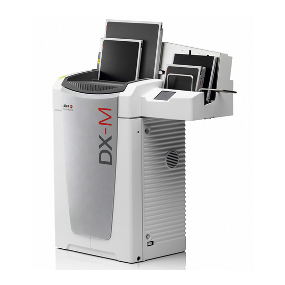
- Page 1 DX-G (type 5170/100) DX-M (type 5170/200) User manual 2321 E EN 20130722...
- Page 2 For more information on Agfa products and Agfa HealthCare products, please visit www.agfa.com. Agfa and the Agfa rhombus are trademarks of Agfa-Gevaert N.V., Belgium or its affiliates. DX-G, DX-M and NX are trademarks of Agfa HealthCare N.V., Belgium or one of its affiliates. All other trademarks are held by their respec- tive owners and are used in an editorial fashion with no intention of infringement.
-
Page 3: Table Of Contents
Recurrent Safety Tests ..................41 Patient Data Security ..................42 Safety Directions ....................43 General Safety Instructions................44 Quality Control ....................46 Getting Started with the DX-G/DX-M .........47 Basic Features....................48 DX-G/DX-M Features..................48 Operating Modes ....................49 Operator Mode ....................49... - Page 4 Stopping the digitizer..................56 Before Switching Off ..................56 Switching Off .....................56 Operating DX-G/DX-M ..............57 Re-erasing an Image Plate ................58 Re-routing of an Image..................60 Turning the Volume of the Digitizer Signals and Beeps On or Off ....63 Changing the Brightness of the Touch Panel ............
- Page 5 DX-G/DX-M Appendix ....................75 Equipment Information Sheet ............77 Specifications ....................78 Pixel Matrix Size ....................82 Technical Documentation ..............83 Compliance....................... 84 Certificates ......................84 Harmonization....................85 Connectivity ..................... 86 Environmental Protection ................86 Remarks for HF-emission and immunity ............88 2321 E EN 20130722...
- Page 6 DX-G/DX-M 2321 E EN 20130722...
-
Page 7: Introduction
Introduction This chapter covers the following topics: Introduction to this Manual ❑ Introduction to DX-G/DX-M ❑... -
Page 8: Introduction To This Manual
DX-G/DX-M Introduction to this Manual This section covers the following topics: Scope Warnings, Cautions, Instructions and Notes Disclaimer 2321 E EN 20130722... -
Page 9: Scope
DX-G/DX-M Scope This manual contains information for safe and effective operation of the DX-G /DX-M digitizers. Warnings, Cautions, Instructions and Notes The following samples illustrate how warnings, cautions, instructions and notes appear in this document. The text explains their intended use. -
Page 10: Disclaimer
DX-G/DX-M Disclaimer Agfa assumes no liability for use of this document if any unauthorized changes have been made to the content or format. Every care has been taken to ensure the accuracy of the information in this document. However, Agfa assumes no responsibility or liability for errors, inaccuracies or omissions that may appear in this document. -
Page 11: Introduction To Dx-G/Dx-M
DX-G/DX-M Introduction to DX-G/DX-M This section covers the following topics: Intended Use Intended User Configuration System Documentation Training Product Complaints Compatibility Compliance Installation Labels Maintenance and Cleaning Recurrent Safety Tests ... -
Page 12: Intended Use
Intended User This manual has been written for trained users of Agfa products and trained diagnostic X–Ray clinical personnel who have received proper training. Users are those persons who actually handle the equipment and those who have authority over the equipment. -
Page 13: Configuration
The documentation consists of following items: • DX-G and DX-M User Manual. • DX-G and DX-M Workflow Sheets. • AGFA CR Detectors, Plates and Cassettes (CR HD5.x, CR MD4.xR, CR HM5.x, CR MM3.xR) User Manual. • CR Full Leg Full Spine User Manual (4408). -
Page 14: Training
DX-G/DX-M Training The user must have received adequate, Agfa certified training on the safe and effective use of the product before attempting to work with it. Training requirements may vary from country to country. The user must ensure that training is received in accordance with local laws or regulations that have the force of law. -
Page 15: Compatibility
Compatibility The digitizer must only be used in combination with other equipment or components if these are expressly recognized by Agfa as compatible. A list of such equipment and components is available from Agfa service on request. Changes or additions to the equipment must only be carried out by persons authorized to do so by Agfa. -
Page 16: Labelling
DX-G/DX-M Labelling CE label: 93/42 EEC 'Medical Devices' (Europe), EN 60601-1 ETLus label: AAMI ES60601-1 (North America) ETLc label: CSA 22.2 No. 60601-1-08 (Canada) Radio Interference Suppression It is hereby certified that the digitizer has interference suppression according to the EN 55011 Class A as well as the FCC Rules CR47 Part 15 Class A. -
Page 17: Equipment Classification
DX-G/DX-M Equipment Classification Class I Equipment Equipment in which protection against electric shock does not rely on basic insulation only, but includes a power sup- ply cord with protective earth conductor. For earth reli- ability always plug the main power cord into an earthed mains power outlet. -
Page 18: Installation
Digitizer installation and configuration is performed by an Agfa certified service engineer. The digitizer is foreseen to be installed in a stationary and weather protected location. -
Page 19: Mobile Use Installation
DX-G/DX-M Mobile Use Installation If the digitizer is installed in a mobile environment, a special mobile version of the DX-M is available that can be locked by the user for transport and un- locked again for use. The locking system consists of two handles on both sides of the digitizer and a locking mechanism for the scan unit. - Page 20 DX-G/DX-M To lock the digitizer before transport: In the Standby window, click the Configuration button. The Rerouting window appears. Click the Mobile use button. hest1200 VAM1254 Leg234 MORLS234 Foot865994 PREVIEWSTAT Wait for the following message to be displayed: “Ready to fix transport locks.
- Page 21 DX-G/DX-M On the right side of the digitizer, turn the two handles 180° clockwise till they reach the locked position: Locked Unlocked Table 2: Locked and unlocked position of the handles Repeat the same using the two handles on the left side of the digitizer.
- Page 22 DX-G/DX-M Insert the locking tool in the round opening in the front cover. Push the tool towards the end and pull tight clockwise by use of the ratchet: Remove the tool. The digitizer is now ready for transport. Caution: If the digitizer is transported without the transport locks attached the device can be damaged.
- Page 23 DX-G/DX-M To unlock the digitizer after transport: Insert the locking tool in the round opening in the front cover. Push the tool towards the end and turn it counterclockwise till mechanical resistance can be felt. On the right side of the digitizer, turn the two handles 180° counterclockwise till they reach the unlocked position: Repeat the same using the two handles on the left side of the digitizer.
- Page 24 DX-G/DX-M Switch on the digitizer. Note: If the digitizer is switched on without removing the transport lock on the front side, the following warning message is displayed: “Transport locks are attached. Switch off the digitizer and remove transport locks.” Image quality check after transport The image quality check must be performed after installation of the digitizer in a mobile environment and is recommended to be repeated after transport.
- Page 25 Identify the cassette as System Diagnosis Mammo - Flat Field Mammo. Table 3: Image quality check after transport Check the flat field image on the NX workstation for homogeneity and stripe artifacts. In case of problems, please inform your local Agfa service representative. 2321 E EN 20130722...
-
Page 26: Labels
DX-G/DX-M Labels Product Identification General Safety Instructions for Laser Products Product Identification DX-G - Product description Type of product Floor-mounted buffer digitizer Commercial name DX-G Model number 5170/100 Original seller/manufacturer Agfa HealthCare N.V. Septestraat 27 2640 Mortsel... -
Page 27: General
A brief overview of these markings and labels and their meaning is given below. Safety warning, indicating that the DX-G/DX-M manuals should be consulted before making any connections to other equipment. The use of accessory equipment not... - Page 28 Insert the cassette as described in the basic workflow of the DX-G/DX-M Workflow Sheets. Off (power: disconnection from the mains) On (power: connection to the mains) Type label...
- Page 29 DX-G/DX-M Observe great care when handling the detectors. The needle detector is shock sensitive and drops should be avoided. When the detector has been dropped, put it aside and con- tact your local service to check for functionality. Caution: Do not use the detector again, a corrupt detector can damage...
-
Page 30: Safety Instructions For Laser Products
DX-G/DX-M Safety Instructions for Laser Products CAUTION! CUIDADO! CLASS 3B LASER RADIATION: RAYO LASER CLASE 3B: WHEN OPEN AVOID DIRECT EVITAR LA EXPOSICIÓN AL HAZ EXPOSURE TO THE BEAM! CUANDO LA TAPA ESTÁ ABIERTA. VORSICHT ! ATTENTION! CLASS 1 LASER PRODUCT... -
Page 31: Maintenance And Cleaning
Regular preventive maintenance needs to be done once a year or after 25000 cycles (whatever comes first). This maintenance can not be done by the user but has to be done by an Agfa certified field service engineer. Not performing the regular maintenance by appropriately certified people can have impact on warranty commitments. -
Page 32: Maintenance By The User
Details about cleaning can be found in the following pages. For cleaning and disinfection instructions of the plates and cassettes, refer to the “AGFA CR Detectors, Plates and Cassettes (CR HD5.x, CR MD4.xR, CR HM5.x, CR MM3.xR) User Manual”. 2321 E EN 20130722... - Page 33 DX-G/DX-M Cleaning the exterior of the digitizer To clean the exterior of the digitizer: Switch off the digitizer. Remove the power plug from the socket. Switch off the UPS, if installed. Wipe the exterior of the digitizer with a clean, soft, damp cloth.
- Page 34 DX-G/DX-M Plug the power plug into the socket. Switch on the UPS, if installed. Cleaning the optical unit The only maintenance action which you must perform is checking the image quality. Refer to the User Manual of the NX Software.
- Page 35 DX-G/DX-M Open the right side cover of the digitizer. Open the eye of the latching and turn the latch through 90° clockwise. Note: In case of a mobile device the upper right lock has to be locked before the side cover can be opened.
- Page 36 DX-G/DX-M Pull out the cleaning brush until you feel the stop position and put it back in the digitizer. Repeat this action 5 times. Close the right side cover. To close the right side cover, proceed as follows: • Close the cover.
- Page 37 DX-G/DX-M Replacing the air-filter element Note: It is advised to replace the air-filter element at least once a year. To change the air-filter element: Switch off the digitizer. Remove the power plug from the socket. Open the right side cover of the digitizer.
- Page 38 Release the 2 clamps (1) to be able to remove the air filter frame (2). Remove the old air-filter element (3). Take-out the new air-filter element. Contact your Agfa representative to order the air-filter element. AGFA ordering code: CM+ 9.5170.9855 2321 E EN 20130722...
- Page 39 DX-G/DX-M Mount the air-filter element inside the rights side door as illustrated below. Note: Mind the air flow arrows imprinted on the air filter when positioning the air-filter inside the door. The air flow arrows should always point to the inside of the machine.
- Page 40 DX-G/DX-M 10 Close the right side cover. To close the right side cover, proceed as follows: • Close the cover. • Turn the latch through 90° counterclockwise and close the eye of the latching. In case of a mobile device, unlock the upper right lock.
-
Page 41: Recurrent Safety Tests
DX-G/DX-M Recurrent Safety Tests The digitizer shall be tested according to IEC 62353* in a time interval of at least 36 months or less if local regulations are different. *Medical electrical equipment – Recurrent test and test after repair of medical electrical equipment. -
Page 42: Patient Data Security
DX-G/DX-M Patient Data Security It is the responsibility of the hospital to ensure how the patients’ legal requirements are to be met, how the security of the patient records are: • maintained and tested, • audited, • administered locally to cover risks from third party access, •... -
Page 43: Safety Directions
The following actions may lead to serious risk of injury and damage to the equipment as well as making the warranty void: Changes, additions or maintenance to the Agfa products carried out by persons without appropriate qualifications and certified train- ing. -
Page 44: General Safety Instructions
Make sure that the digitizer is constantly monitored in order to avoid inappro- priate handling, especially by children. Only service personnel with certified Agfa training must make repairs. Only authorized service personnel must make changes to the digitizer. - Page 45 DX-G/DX-M The digitizer complies with the EN 60601-1 and UL 60601-1 standards for Med- ical Electrical Equipment. This means that, although it is absolutely safe, patients may not come in direct contact with the equipment. Therefore the operator console must be placed outside the radius as listed below around the patient (according to the local valid regulation).
-
Page 46: Quality Control
Regular Quality Control has to be applied according the local regulations. If no specific regulations are valid, a regular quality control applied with the Agfa Auto QC² tool at least once a month is required to maintain a safe and effective system. -
Page 47: Getting Started With The Dx-G/Dx-M
Getting Started with the DX-G/DX-M This chapter explains how to perform the first basic actions on the digitizer. This chapter covers the following topics: Basic Features ❑ ❑ The User Interface Starting the Digitizer ❑ ❑ Basic Workflow (Scanning Images) Stopping the digitizer ❑... -
Page 48: Basic Features
Features. Operating Modes. DX-G/DX-M Features The digitizer reads out the latent X-ray images on image plates and sends them to the workstation. The digitizer has an input and output buffer for 5 cassettes. Consecutively on each cassette in the buffer, the digitizer: •... -
Page 49: Operating Modes
DX-G/DX-M Operating Modes The digitizer can be operated in two modes: Operator Mode Service Mode Operator Mode The operator mode groups all basic functions which are aimed at radiographers: • Re-erasing an image plate. • Rerouting of images. -
Page 50: The User Interface
DX-G/DX-M The User Interface The digitizer has two operation modes: • the operator mode for basic operation, • the service mode reserved for trained service personnel. The functions of the operator mode are described in this manual. The digitizer interfaces with the user via: •... -
Page 51: Status Indicator
Service mode Check digitizer touch • • panel and workstation display for further infor- mation and detailed instructions. Fatal error Contact an Agfa certi- • • fied service engineer. Flashing Check digitizer touch Warm up / Self-test • panel and workstation Processing Software down •... -
Page 52: Starting The Digitizer
DX-G/DX-M Starting the Digitizer Procedure: Make sure the digitizer is connected to a workstation and that the workstation is running the appropriate NX Software. Make sure that the power plug is plugged into the socket. Remove cassettes from the input buffer and input slot of the digitizer. - Page 53 DX-G/DX-M The Start Up screen is visible on the Touch panel: The digitizer starts the following operation sequence: initialization of all components, • functional test of all components, • check for presence of cassettes and/or IPs. • During the warm-up and self-test, which may take up to 3 minutes, the digitizer status indicator is flashing red.
-
Page 54: Basic Workflow (Scanning Images)
DX-G/DX-M Basic Workflow (Scanning Images) Note: The basic workflow is described in the DX-G/DX-M Workflow Sheets. Workflow: Identify the cassette with the ID Tablet and on a workstation. Check that the digitizer is ready for operation. The status indicator must be continuously lighting up green or green flashing. - Page 55 DX-G/DX-M Tube side must be faced to the operator. • The shutter opening mechanism and locking mechanism must be pointed down, to • the slot of the digitizer. The cassettes are digitized subsequently: The status indicator is green and blinking.
-
Page 56: Stopping The Digitizer
DX-G/DX-M Stopping the digitizer Before Switching Off. Switching Off. Before Switching Off Check that the digitizer is not scanning an image plate. If the digitizer is scanning an image plate, the status indicator is flashing green. Switching Off It is recommended to switch off the digitizer at the end of the day. -
Page 57: Operating Dx-G/Dx-M
Operating DX-G/DX-M This chapter provides information about functions that are available in operator mode. Finally you will find some preventive maintenance and troubleshooting guidelines. This chapter covers the following topics: Re-erasing an Image Plate ❑ ❑ Turning the Volume of the Digitizer Signals and Beeps On or Off Changing the Brightness of the Touch Panel ❑... -
Page 58: Re-Erasing An Image Plate
DX-G/DX-M Re-erasing an Image Plate At the end of a digitizing cycle, the digitizer returns an erased image plate. However, in the following cases, you must re-erase the image plate before re- using it in order to prevent ghost images from interfering with the image of interest: GenRad: If the image plate has not been used for more than 48 hours. - Page 59 DX-G/DX-M Put the cassettes containing the image plate on the cassette buffer [1] of the digitizer as shown below. Make sure to insert the cassette with the black (tube) side to the front and with the shutter opening mechanism and the locking mechanism down, towards the cassette slot.
-
Page 60: Re-Routing Of An Image
DX-G/DX-M Re-routing of an Image Normally, an image is sent to the workstation where it was identified. But in case of transmission problems, the image can be rerouted on the digitizer and sent to an alternative workstation. WARNING: The demographic data selected during original identification are lost. - Page 61 DX-G/DX-M Chest1200 VAM1254 Leg234 MORLS234 Foot865994 PREVIEWSTAT 1. Image UID. 2. Workstation. 3. Status: T - Transmitting (the digitizer is busy transmitting the image) / W - Warning (the image transmission has failed; manual re-transmission to a new workstation necessary) / Q - Queued (the image is in the transmission queue;...
- Page 62 DX-G/DX-M Click the Destinations button. The following window appears. VAM1254 MORLS234 PREVIEWSTAT MORWF452 MORWF475 HOUSE M.D. E.R. GRACE ANATOMY AGFA UZA 452 MY OFFICE Select the new workstation and confirm by clicking the Confirm button. 2321 E EN 20130722...
-
Page 63: Turning The Volume Of The Digitizer Signals And Beeps On Or Off
DX-G/DX-M Turning the Volume of the Digitizer Signals and Beeps On or Off You can turn the volume of digitizer signals and beeps on or off. To turn the volume on or off: In the Standby window, click the Configuration button. - Page 64 DX-G/DX-M The following window appears. The active functionality lights up in blue (here: volume ON) Do one of the following: Turn the volume on by pressing the button. • Turn the volume off by pressing the button. • As a result the selected button lights up in blue.
-
Page 65: Changing The Brightness Of The Touch Panel
DX-G/DX-M Changing the Brightness of the Touch Panel You can change the brightness of the touch panel on the digitizer. To change the brightness: In the Standby window, press the Configuration button. Configuration button The Configuration window appears: Chest1200 VAM1254... - Page 66 DX-G/DX-M The following window appears. Brightness Section of the Configuration Screen In the Brightness section on the lower part of the Configuration window, use the + or - buttons to adjust the brightness. 2321 E EN 20130722...
-
Page 67: Retrieving Information About The Digitizer
DX-G/DX-M Retrieving Information About the Digitizer To retrieve information: In the Standby window, press the Information button. Information button The Information window appears, showing the IP Address, Name, Software version and name of the primary NX workstation: Confirmation button Click the Confirm button to go back to the Standby window. -
Page 68: Moving The Digitizer
DX-G/DX-M Moving the Digitizer To move the digitizer: Switch off the digitizer. Remove the power plug from the socket. Unplug the ethernet cable. Collect all cables together to prevent them from being crushed when moving the digitizer. Remove all cassettes from the input and output buffer. - Page 69 DX-G/DX-M Take the tool from the tool box at the inside of the right door. Insert the tool in the opening and turn the screw counterclockwise, until the digitizer is lifted up approximately 1,5-2 cm, until you encounter resistance. 1,5 - 2 cm 0.59 - 0.78 inch...
- Page 70 DX-G/DX-M Move the digitizer to the desired location. WARNING: Observe great care when moving the digitizer to the desired location. So please select a path free from inclinations and thresholds to prevent the digitizer from shocks during movement. 10 Once on the desired site, turn the screw clockwise until the digitizer is fixed on the ground and you encounter resistance.
-
Page 71: Troubleshooting And Errors During Operation
If the status indicator is continuously lighting up in red, your digitizer deals with a fatal error. Proceed as follows: Do not try to solve this problem. Contact immediately your Agfa certified service engineer for more information. Figure 5: Example fatal error (status indicator continuously red) 2321 E EN 20130722... -
Page 72: Status Indicator: Flashing Red
DX-G/DX-M Status Indicator: flashing red If the status indicator is flashing red, your digitizer deals with an error that can be remedied by the operator. Always follow the instructions that appear on the touch panel. For example; if you wrongly insert the cassette, with the exposed and... -
Page 73: Digitizer Does Not Start Up
DX-G/DX-M Digitizer does not Start up If the digitizer does not start up, check the power supply, wall socket and safety fuse. If the power supply is ok, call your local Service engineer. 2321 E EN 20130722... - Page 74 DX-G/DX-M 2321 E EN 20130722...
-
Page 75: Appendix
Appendix... - Page 76 DX-G/DX-M 2321 E EN 20130722...
-
Page 77: Equipment Information Sheet
Equipment Information Sheet This appendix covers the following topic: Specifications ❑ ❑ Pixel Matrix Size... -
Page 78: Specifications
DX-G/DX-M Specifications Dimensions Max. Height 1229 mm (48.4 inch) Max Floor space WxD 660 mm x 510 mm (26.0 inch x 20.1 inch) Max Projected Floor space WxD 1150 mm x 510 mm (45.3 inch x 20.1 inch) Weight Unpacked approximately 180.0 kg (396.8 lb) - Page 79 Environmental conditions (during operation) In line with IEC721-3-2: 2M2 and 2K2 with following restrictions: Room temperature Agfa CR HM5.x Mammo: between +20 °C and +30 °C (68 - 86°F) Other plates and cassettes: between +15 °C and +30 °C (59 - 86°F) Maximum temperature change rate max.
- Page 80 Environmental conditions for mobile installation (during operation) In line with IEC721-3-3: 3M1 and 3K2 with following restrictions: Room temperature Agfa CR HM5.x Mammo: between +20 °C and +30 °C (68 - 86°F) Other plates and cassettes: between +15 °C and +30 °C (59 - 86°F)
- Page 81 (if regularly serviced and maintained according to Agfa instructions) Preventive maintenance Preventive maintenance frequency. Once a year or 25000 cycles, whatever comes first. Note: Needs to be done by an Agfa certified field service engineer. 1. BTU: British Thermal Unit 2321 E EN 20130722...
-
Page 82: Pixel Matrix Size
DX-G/DX-M Pixel Matrix Size Cassette Format (cm) Resolution Width x Length Width x Length type (pixel/mm) (pixels) (mm) 35x43 HR 4248 x 3480 424.8 x 348.0 MD4.0R 35x35 HR 3480 x 3480 348.0 x 348.0 General 35x43 SR 6.66 2832 x 2320 424.8 x 348.0... -
Page 83: Technical Documentation
Technical Documentation This appendix contains technical information. It is only available in English. Compliance ❑ Connectivity ❑ ❑ Environmental Protection Remarks for HF-emission and immunity ❑... -
Page 84: Compliance
ES 60601-1 1st Edition; CAN CSA 22.2 no. 60601-1-08 Laser IEC 60825-1:1993 + A1:1997 CFR parts 1040.10 and 1040.11 + A2:2001 CSA-E60825-1-03 Note: The DX-G/DX-M is in compliance with the EG regulation 93/42/EEC Directive (Medical Device). 2321 E EN 20130722... -
Page 85: Harmonization
It is a multilateral agreement among participating countries and certification organizations. Agfa has produced a CB test report and claims national certification in all other member countries of the CB Scheme. -
Page 86: Connectivity
For more detailed information about take-back and recycling of this product please contact your local Agfa service organization and/or Agfa dealer. By ensuring this product is disposed of correctly, you will help prevent potential negative consequences for the environment and human health, which could otherwise be caused by inappropriate waste handling of this product. - Page 87 DX-G/DX-M This wheeled bin symbol on batteries or its packaging may be used in combination with a chemical symbol. In cases where a chemical symbol is available it indicates the presence of respective chemical substances. If your equipment or replaced spare parts contain batteries or accumulators please dispose of them separately according to local regulations.
-
Page 88: Remarks For Hf-Emission And Immunity
DX-G/DX-M Remarks for HF-emission and immunity The DX-G/DX-M has been tested for a normal hospital environment as described below. The user of the device should ensure that it is used in such an environment. Nevertheless the HF-emission and immunity can be influenced by connected data cables depending on length and the manner of installation. - Page 89 DX-G/DX-M This device is intended for operation in the electromagnetic environment given below. The user of the device should ensure that it is used in such an environment. Resistance to IEC 60601 Level of Electromagnetic Environ- Jamming Test Test Level...
- Page 90 DX-G/DX-M This device is intended for operation in the electromagnetic environment given below. The user of the device should ensure that it is used in such an environment. Tests of Resistance IEC 60601 Level of Electromagnetic Environment to Disruption Test Level...
- Page 91 DX-G/DX-M REMARK 1: The higher value will apply at 80 MHz and 800 MHz. REMARK 2: These Guidelines may not apply to all situations. The dispersion of electromagnetic waves is influenced by absorption and reflections from buildings, objects and people.
- Page 92 DX-G/DX-M The distance can be determined through the equation for each respective column. P is the rated power of the transmitter in watts (W) according to the manufacturer infor- mation on the transmitter, only for transmitters where the rated power is not mentioned in the above table.
- Page 93 DX-G/DX-M 2321 E EN 20130722...
- Page 94 Printed in Belgium Published by Agfa HealthCare N.V., B-2640 Mortsel-Belgium 2321 E EN 20130722...