Juniper MX204 Hardware Manual
3d universal edge router
Hide thumbs
Also See for MX204:
- Hardware manual (191 pages) ,
- Quick start manual (26 pages) ,
- Quick start manual (31 pages)

Related Manuals for Juniper MX204


Summary of Contents for Juniper MX204
- Page 1 MX204 3D Universal Edge Router Hardware Guide Modified: 2018-06-11 Copyright © 2018, Juniper Networks, Inc.
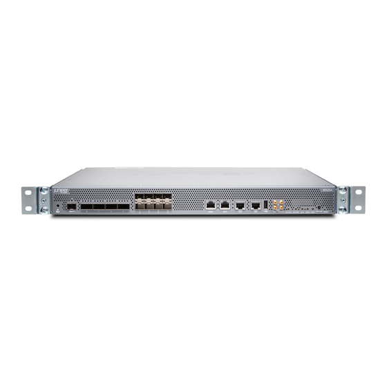
- Page 2 MX204 3D Universal Edge Router Hardware Guide Figure 1: Front View of the MX204 Router The MX204 router is a fixed-configuration router, and supports one built-in Routing Engine. The router runs on AC or DC power, with two dedicated power supply modules on each device.
- Page 3 The MX204 has four rate-selectable ports that can be configured as 100-Gigabit Ethernet ports or 40-Gigabit Ethernet ports, or each port can be configured as four 10-Gigabit Ethernet ports (by using a breakout cable). The MX204 also has eight 10-Gigabit Ethernet ports. The four rate-selectable ports support QSFP28 and QSFP+ transceivers, whereas the eight 10-Gigabit Ethernet ports support SFP+ transceivers.
- Page 4 MX204 3D Universal Edge Router Hardware Guide Figure 3: Rear View of the AC-Powered MX204 Router 1— Fan modules 2— Power supply modules (AC) Figure 4: Rear View of the DC-Powered MX204 Router 1— Fan modules 2— Power supply modules (DC) The electrostatic discharge (ESD) points on the router are located both on the front and on the rear of the chassis.
- Page 5 MX204 Router Overview on page 3 Documentation Locating the Serial Number on an MX204 Router or Component on page 125 Guidelines for Packing Hardware Components for Shipment on page 122 Returning a Hardware Component to Juniper Networks, Inc. on page 123...
- Page 6 MX204 3D Universal Edge Router Hardware Guide MX204 Hardware Components and CLI Terminology The MX204 router support the components in Table 4 on page 8, listed in alphabetic order. Table 4: MX204 Router Hardware Components and CLI Terminology Component Hardware Model Number CLI Name Description Chassis MX204 “MX204 Chassis Description”...
- Page 7 Figure 4 on page 6 shows the rear of the fully configured chassis. Table 6 on page 9 lists the components on the rear panel of the MX204 router. Table 6: Rear Panel Components in a Fully Configured MX204 Router Component...
- Page 8 CHAPTER 3 Cooling System MX204 Cooling System Description on page 11 MX204 Fan Status LED on page 13 MX204 Cooling System Description The cooling system components work together to keep all router components within the acceptable temperature range. The cooling system consists of the following features and components:...
- Page 9 MX204 3D Universal Edge Router Hardware Guide Figure 6: Fan Module 1— Captive screw 2— Latch Airflow The router has front-to-back (AIR OUT) cooling system (see Figure 7 on page 12). Air is pulled through the front the chassis toward the fan tray, where it is exhausted out of the system.
- Page 10 Replacing an MX204 DC Power Supply on page 99 Replacing an MX204 Fan Module on page 95 MX204 Fan Status LED The MX204 fan module does not have any LED—the fan status LEDs are located on the MX204 chassis. Figure 8 on page 13 shows the fan status LEDs.
- Page 11 Routing Engine Interface Ports on page 16 Routing Engine Functions The Routing Engine is built-in on the MX204 baseboard and cannot be replaced. The Routing Engine performs all route-processing functions, and provides performs chassis control and management plane functionality. The Routing Engine also provides control plane functions.
- Page 12 The Routing Engine consists of the following internal components: High-performance 1.6-GHz Intel 8 Core X86 CPU 32-GB DDR4 RAM 100-GB SATA SSD Routing Engine Front Panel Figure 9 on page 16 shows the front panel of the MX204 chassis. Figure 9: MX204 Ports 1— Rate-selectable ports 9— RESET button 2—...
- Page 13 RJ-45 Connector Pinouts for an MX Series CB-RE or RCB Management Port on page 56 MX204 Chassis Description on page 5 MX204 Routing Engine LEDs The Routing Engine is built-in on the MX204 and is attached to the baseboard and cannot be replaced. The status of the Routing Engine is displayed by the ONLINE OK/FAIL LEDs on the front panel of the MX204 chassis.
- Page 14 MX204 3D Universal Edge Router Hardware Guide Table 9: MX204 LEDs Label Color State Description Green On steadily Both Junos OS and Linux are successfully loaded on ONLINE the router. Blinking Router is starting Junos OS. On steadily Router has loaded Linux.
- Page 15 When there is loss of signal or loss of line. (Link LED; right) – When there is no loss (BITS is in locked state). (Link LED; right) Related MX204 Routing Engine Description on page 15 Documentation Copyright © 2018, Juniper Networks, Inc.
- Page 16 MX204 Power Supply Module LEDs on page 23 MX204 Power System Description The MX204 is powered using either AC or DC power. It supports two power supply modules (PSMs) located at the rear of the chassis in slots Figure 10 on page 22 Figure 11 on page 23 show the MX204 PSMs.
- Page 17 MX204 3D Universal Edge Router Hardware Guide AC Power Supply Description Each AC power supply weighs approximately 2.2 lb (1 kg) and consists of a handle, an ejector lever, an AC appliance inlet, a fan, and status LEDs to monitor the status of the power supply.
- Page 18 Chapter 5: Power System Components and Descriptions Figure 11: DC Power Supply Related MX204 Power Supply Module LEDs on page 23 Documentation Maintaining the MX204 Power Supplies on page 116 MX204 Router AC Power Specifications on page 43 MX204 Router DC Power Specifications on page 49...
- Page 19 MX204 3D Universal Edge Router Hardware Guide Figure 13 on page 24 shows the AC power supply module components with the AC power cord retainer along with the status LEDs. Figure 13: AC Power Supply Module LEDs and Components––with the AC Power Cord Retainer 1—...
- Page 20 Related Routine Maintenance Procedures for MX204 Routers on page 113 Documentation MX204 Power System Description on page 21 Maintaining the MX204 Power Supplies on page 116...
- Page 21 Preparation Overview on page 29 Transceiver and Cable Specifications on page 37 AC Power Requirements, Specifications, and Guidelines on page 43 DC Power Requirements, Specifications, and Guidelines on page 49 Pinout Specifications on page 55 Copyright © 2018, Juniper Networks, Inc.
- Page 22 MX204 Router Environmental Specifications on page 30 MX204 Router Grounding Specifications on page 30 MX204 Router Rack Requirements on page 32 MX204 Router Cabinet Requirements and Specifications on page 33 MX204 Router Clearance Requirements for Airflow and Hardware Maintenance on page 34...
- Page 23 Articles 110-16, 110-17, and 110-18 of the National Electrical Code, ANSI/NFPA 70. Related Routine Maintenance Procedures for MX204 Routers on page 113 Documentation General Safety Guidelines for Juniper Networks Devices General Safety Warnings for Juniper Networks Devices on page 134...
- Page 24 This two-holed bracket attaches on the side of the chassis through the mounting rail and provides a protective earthing terminal for the router. The grounding points are studs sized for 10–32 screws. The 10–32 screws are provided with the MX204 router. The grounding points are spaced at 0.75-in. (19.1-mm) centers.
- Page 25 MX204 3D Universal Edge Router Hardware Guide MX204 Router Rack Requirements The MX204 router can be installed in a standard 19-in. rack. Many types of racks are acceptable, including four-post (telco) racks and open-frame racks. Table 14 on page 32 summarizes rack requirements and specifications for the router.
- Page 26 Equipment (document number EIA-310-D) published by the Electronic Components Industry Association (ECIA) ( http://www.ecianow.org With adequate cooling air and airflow clearance, you can stack multiple MX204 routers in a cabinet with a four-post rack. In all cases, the rack must meet the strength requirements to support the weight.
- Page 27 MX204 Site Preparation Checklist on page 35 MX204 Installation Summary on page 63 MX204 Cooling System Description on page 11 MX204 Router Clearance Requirements for Airflow and Hardware Maintenance When planning the installation site, allow sufficient clearance around the rack (see Figure 17 on page...
- Page 28 Chapter 6: Preparation Overview Figure 17: MX204 Chassis Dimensions and Clearance Requirements Related MX204 Site Preparation Checklist on page 35 Documentation MX204 Router Rack Requirements on page 32 MX204 Router Physical Specifications on page 29 MX204 Site Preparation Checklist The checklist in...
- Page 29 Related MX204 Installation Summary on page 63 Documentation Tools Required to Install the MX204 Chassis in Rack on page 64 Installing the MX204 Chassis in a Rack on page 65 Copyright © 2018, Juniper Networks, Inc.
- Page 30 You can use the Hardware Compatibility Tool to find information about the pluggable transceivers supported on your Juniper Networks device. To calculate the power budget and power margin, perform the following tasks: Calculating Power Budget for Fiber-Optic Cable on page 37...
- Page 31 MX204 3D Universal Edge Router Hardware Guide = 13 dB Calculating Power Margin for Fiber-Optic Cable After calculating a link's power budget, you can calculate the power margin (P ), which represents the amount of power available after subtracting attenuation or link loss (LL) from the power budget (P ).
- Page 32 One 4.57-m 100 m RJ-45 Ethernet or equivalent length with autosensing interface suitable for RJ-45/RJ-45 100Base-T connectors operation Alarm relay Wire with gauge None — contacts between 28-AWG and 14-AWG (0.08 and 2.08 mm Copyright © 2018, Juniper Networks, Inc.
- Page 33 MX204 3D Universal Edge Router Hardware Guide Understanding Fiber-Optic Cable Signal Loss, Attenuation, and Dispersion This topic describes signal loss, attenuation, and dispersion in fiber-optic cable. Signal Loss in Multimode and Single-Mode Fiber-Optic Cable on page 40 Attenuation and Dispersion in Fiber-Optic Cable on page 40...
- Page 34 MX204 Router AC Power Specifications on page 43 Power Consumption for an AC-Powered MX204 Router on page 44 AC Power Circuit Breaker Requirements for the MX204 Router on page 45 AC Power Cord Specifications for MX204 Routers on page 46...
- Page 35 Documentation Maintaining the MX204 Power Supplies on page 116 AC Power Circuit Breaker Requirements for the MX204 Router on page 45 Power Consumption for an AC-Powered MX204 Router Use the information in this topic to determine the power consumption for your router and plan the amount of power you need to provide to the router.
- Page 36 Table 23 on page 45 lists the power requirements for the fully configured AC-powered routers operating under maximum voltage conditions. Table 23: MX204 Router AC Router Power Requirements at Maximum Temperature (55° Power Requirement at 55° C Power Requirement (Watts)
- Page 37 MX204 3D Universal Edge Router Hardware Guide Prevention of Electrostatic Discharge Damage on page 156 AC Power Cord Specifications for MX204 Routers A detachable AC power cord is supplied with the AC power supply modules. The coupler is type C13 as described by International Electrotechnical Commission (IEC) standard 60320.
- Page 38 Table 24 on page Figure 18: AC Plug Types Related MX204 Router AC Power Specifications on page 43 Documentation General Safety Guidelines and Warnings on page 133 General Electrical Safety Guidelines and Warnings on page 155 Prevention of Electrostatic Discharge Damage on page 156...
- Page 39 MX204 Router DC Power Specifications on page 49 Power Consumption for a DC-Powered MX204 Router on page 50 DC Power Circuit Breaker Requirements for the MX204 Router on page 51 DC Power Source Cabling for MX204 Router on page 52...
- Page 40 Maintaining the MX204 Power Supplies on page 116 Replacing an MX204 DC Power Supply on page 99 DC Power Circuit Breaker Requirements for the MX204 Router on page 51 Power Consumption for a DC-Powered MX204 Router Use the information in this topic to determine the power consumption for your router and plan the amount of power you need to provide to the router.
- Page 41 Chapter 9: DC Power Requirements, Specifications, and Guidelines Table 29: MX204 Router DC Router Power Requirements at Maximum Temperature (55° Power Requirement at 55° C Power Requirement (Watts) Chassis Configuration (Watts) with 90% Efficiency Fully configured chassis 280 W 311 W...
- Page 42 Replacing an MX204 DC Power Supply on page 99 Power Consumption for a DC-Powered MX204 Router on page 50 DC Power Circuit Breaker Requirements for the MX204 Router on page 51 DC Power Cable Specifications for MX204 Router on page 53...
- Page 43 MX204 Router DC Power Specifications on page 49 Power Consumption for a DC-Powered MX204 Router on page 50 DC Power Circuit Breaker Requirements for the MX204 Router on page 51 DC Power Source Cabling for MX204 Router on page 52...
- Page 44 Table 30: RJ-45 Connector Pinout for the AUX and CONSOLE Ports Signal Description Request to Send Data Terminal Ready Transmit Data Ground Signal Ground Ground Signal Ground Receive Data DSR/DCD Data Set Ready Clear to Send Copyright © 2018, Juniper Networks, Inc.
- Page 45 MX204 3D Universal Edge Router Hardware Guide Related CB-RE and RCB Interface Cable and Wire Specifications for MX Series Routers on Documentation page 39 RJ-45 Connector Pinouts for an MX Series CB-RE or RCB Management Port The port on the Control Board and Routing Engine (CB-RE; Routing and Control Board...
- Page 46 Unpacking the Router on page 59 Installing the Router on page 63 Connecting the Router to Power on page 71 Connecting the Router to the Network on page 83 Configuring Junos OS on the Router on page 89 Copyright © 2018, Juniper Networks, Inc.
- Page 47 CHAPTER 11 Unpacking the Router Tools and Parts Required to Unpack the MX204 Router on page 59 Unpacking MX204 Router on page 59 Verifying the MX204 Router Parts Received on page 60 Tools and Parts Required to Unpack the MX204 Router...
- Page 48 MX204 Site Preparation Checklist on page 35 Documentation MX204 Installation Summary on page 63 Tools and Parts Required to Unpack the MX204 Router on page 59 Verifying the MX204 Router Parts Received on page 60 Verifying the MX204 Router Parts Received A packing list is included in each shipment.
- Page 49 ETSI brackets Related MX204 Site Preparation Checklist on page 35 Documentation MX204 Installation Summary on page 63 Tools and Parts Required to Unpack the MX204 Router on page 59 Unpacking MX204 Router on page 59 Copyright © 2018, Juniper Networks, Inc.
- Page 50 “Installing the MX204 Chassis in a Rack” on page (Optional; Required only if you have removed the components from the router in step 4) Reinstall components in the MX204 router after installing the chassis in a rack. See individual topics listed in Removing, Installing, and Upgrading Components for installing components.
- Page 51 MX204 3D Universal Edge Router Hardware Guide Connect cables to the network and external devices. “Connecting the MX204 Router to External Devices and Cables” on page Connect the grounding cable. “Grounding the MX204 Router” on page Connect the AC power cord or DC power cables: “Connecting Power to an AC-Powered MX204 Router”...
- Page 52 The fully loaded chassis weighs approximately 22.7 lb (10.3 kg). The MX204 router is designed for installation in a rack that complies with either of the following standards: 19-in.
- Page 53 MX204 3D Universal Edge Router Hardware Guide Figure 20: Attaching the Mounting Brackets Using a Phillips (+) number 2 screwdriver, secure the mounting brackets to the router using the mounting screws. With one person on each side, hold on to the bottom of the chassis and carefully lift it so that the mounting brackets contact the rack rails.
- Page 54 Figure 24: Router Installed in the Rack Installing the MX204 in a 21-in. ETSI Rack The ETSI racks are little wider than the standard 19-in. rack. To install the router in an ETSI rack, you need to install the ETSI brackets on to the router.
- Page 55 MX204 3D Universal Edge Router Hardware Guide To install the router in a 21-in. ETSI rack or cabinet: Position the router in front of the rack or cabinet. Attach an electrostatic discharge (ESD) grounding strap to your bare wrist and to a site ESD point.
- Page 56 On the rear of the chassis, slide the rear-mounting brackets (with the ETSI brackets installed) on either side of the chassis until the rear-mounting brackets contact the rack rails (see Figure 31 on page 69). Figure 31: Installing the Rear-Mounting Brackets with ETSI Brackets Copyright © 2018, Juniper Networks, Inc.
- Page 57 MX204 Router Grounding Specifications on page 30 MX204 Router Clearance Requirements for Airflow and Hardware Maintenance on page 34 Tools and Parts Required for MX204 Router Grounding and Power Connections on page 71 Tools Required to Install the MX204 Chassis in Rack on page 64...
- Page 58 Powering On a DC-Powered MX204 Router on page 80 Powering Off the MX204 Router on page 81 Tools and Parts Required for MX204 Router Grounding and Power Connections To ground and provide power to the router, you need the following tools and parts:...
- Page 59 You must provide the grounding cables (the cable lugs are supplied with the router). For grounding cable specifications, see “MX204 Router Grounding Specifications” on page Figure 33: Grounding Point on the MX204 Router Rear panel 1— Grounding point To ground the router: Verify that a licensed electrician has attached the cable lug provided with the router to the grounding cable.
- Page 60 Figure 34: Connecting Grounding Lug to the MX204 Router Related Tools and Parts Required for MX204 Router Grounding and Power Connections on Documentation page 71 Connecting Power to an AC-Powered MX204 Router on page 73...
- Page 61 MX204 3D Universal Edge Router Hardware Guide Connect the power cord to the power supply source. NOTE: Each power supply must be connected to a dedicated AC power feed and a dedicated customer-site circuit breaker. We recommend that you use a dedicated customer-site circuit breaker rated for 20 A (110 VAC) or 16 A (220 VAC) minimum, or as required by local code.
- Page 62 Repeat Step through Step for the installing the remaining power supply. Figure 37: Connecting AC Power to the Router Related Tools and Parts Required for MX204 Router Grounding and Power Connections on Documentation page 71 Copyright © 2018, Juniper Networks, Inc.
- Page 63 MX204 3D Universal Edge Router Hardware Guide Powering On an AC-Powered MX204 Router on page 76 MX204 Router Grounding Specifications on page 30 General Safety Guidelines and Warnings on page 133 General Electrical Safety Guidelines and Warnings on page 155...
- Page 64 On the external management device connected to the Routing Engine, monitor the startup process to verify that the system has booted properly. Related Tools and Parts Required for MX204 Router Grounding and Power Connections on Documentation page 71 Connecting Power to an AC-Powered MX204 Router on page 73...
- Page 65 You must provide the power cables (the cable lugs are supplied with the router). For power cable specifications, “DC Power Cable Specifications for MX204 Router” on page To connect the DC source power cables to the router for each power supply: Switch off the dedicated customer-site circuit breakers.
- Page 66 Figure 38: Connecting DC Power to the Router Related Tools and Parts Required for MX204 Router Grounding and Power Connections on Documentation page 71 Powering On a DC-Powered MX204 Router on page 80...
- Page 67 MX204 3D Universal Edge Router Hardware Guide Powering On a DC-Powered MX204 Router To power on a DC-powered router: Verify that an external management device is connected to the port on the chassis. Turn on power to the external management device.
- Page 68 156. Ensure that you do not need to route traffic through the MX204. Ensure that you have the following parts and tools available to power off the MX204: An ESD grounding strap An external management device such as a PC...
- Page 69 Attach an ESD grounding strap to your bare wrist and connect the strap to one of the ESD points on the chassis. Switch off the power supply source. Related Powering On an AC-Powered MX204 Router on page 76 Documentation Powering On a DC-Powered MX204 Router on page 80 request vmhost halt...
- Page 70 CHAPTER 14 Connecting the Router to the Network Tools and Parts Required to Connect the MX204 Router to External Devices on page 83 Connecting the MX204 Router to External Devices and Cables on page 83 Tools and Parts Required to Connect the MX204 Router to External Devices To connect the router to external devices, you need the following tools and parts: 2.5-mm flat-blade (–) screwdriver for the alarm relay contacts...
- Page 71 MX204 3D Universal Edge Router Hardware Guide Figure 39: MX204 Front Panel Ports, LEDs and Buttons 1— Rate-selectable ports 9— RESET button 2— MGMT 10— SSD0 Management ( ) port 3— BITS 11— port with LEDs Alarm ( ) LED 4—...
- Page 72 Chapter 14: Connecting the Router to the Network Table 34: Out-of-Band Management Port on the MX204 Router Callout Label Description Dedicated management channel for MGMT device maintenance. It is also used by (See system administrators to monitor and Figure 39 on page manage the router remotely.
- Page 73 MX204 3D Universal Edge Router Hardware Guide Figure 42: Connecting the MX204 Router to a Management Console Through a Console Server To Console port Console server Figure 43: Connecting the MX204 Router Directly to a Management Console Table 35: Console Port on the MX204 Router...
- Page 74 Ensure that the 10-MHz or 1-PPS source network equipment contains low voltage complementary metal oxide semiconductor (LVCMOS) or is compatible with low-voltage (3.3 V) transistor–transistor logic (LVTTL). Table 36: Clocking Port on the MX204 Router Callout Label Description GPS input and output ports.
- Page 75 Plug the other end of the RJ-45 cable into the BITS external clocking device. Verify that the LEDs for the BITS port are lit steadily green. Configure the port. See Configuring Clock Synchronization Interface on MX Series Routers. Table 38: BITS Port on the MX204 Router Callout Label Description BITS Building-Integrated Timing Supply (BITS) clock interface port with LED.
- Page 76 CHAPTER 15 Configuring Junos OS on the Router Performing the Initial Software Configuration for the MX204 Router on page 89 Performing the Initial Software Configuration for the MX204 Router The router is shipped with the Junos operating system (OS) preinstalled and ready to be configured when the router is powered on.
- Page 77 MX204 3D Universal Edge Router Hardware Guide Start the CLI. For more information about CLI commands, see the CLI Explorer root# cli root@> Enter configuration mode. cli> configure [edit] root@# Configure the name of the router. If the name includes spaces, enclose the name in quotation marks (“...
- Page 78 (Optional) Display the configuration to verify that it is correct. [edit] root@# show system { host-name host-name; domain-name domain-name; backup-router address; root-authentication { authentication-method (password | public-key); name-server { address; interfaces { fxp0 { unit 0 { family inet { address address/prefix-length; Copyright © 2018, Juniper Networks, Inc.
- Page 79 MX204 3D Universal Edge Router Hardware Guide Commit the configuration to activate it on the router. [edit] root@# commit (Optional) Configure additional properties by adding the necessary configuration statements. Then commit the changes to activate them on the router. [edit] root@host# commit When you have finished configuring the router, exit configuration mode.
- Page 80 PART 4 Removing, Installing, and Upgrading Components Replacing Cooling System Components on page 95 Replacing Power System Components on page 97 Replacing Transceivers on page 105 Copyright © 2018, Juniper Networks, Inc.
- Page 81 CHAPTER 16 Replacing Cooling System Components Replacing an MX204 Fan Module on page 95 Replacing an MX204 Fan Module Removing an MX204 Fan Module on page 95 Installing an MX204 Fan Module on page 96 Removing an MX204 Fan Module...
- Page 82 Figure 45: Installing the Fan Module Related MX204 Cooling System Description on page 11 Documentation Maintaining the MX204 Fan Module on page 115 Prevention of Electrostatic Discharge Damage on page 156 Copyright © 2018, Juniper Networks, Inc.
- Page 83 CHAPTER 17 Replacing Power System Components Replacing an MX204 AC Power Supply on page 97 Replacing an MX204 DC Power Supply on page 99 Replacing an MX204 AC Power Supply Removing an MX204 AC Power Supply on page 97 Installing an MX204 AC Power Supply on page 98...
- Page 84 MX204 3D Universal Edge Router Hardware Guide To remove an AC power supply (see Figure 46 on page 98): Switch off the dedicated customer-site circuit breaker for the power supply, and remove the power cord from the AC power source. Follow the instructions for your site.
- Page 85 MX204 Power System Description on page 21 Documentation MX204 Router AC Power Specifications on page 43 AC Power Circuit Breaker Requirements for the MX204 Router on page 45 Prevention of Electrostatic Discharge Damage on page 156 Replacing an MX204 DC Power Supply...
- Page 86 MX204 3D Universal Edge Router Hardware Guide CAUTION: To maintain proper cooling and prevent thermal shutdown of the operating power supply unit, each power supply slot must contain either a power supply or a blank panel. If you remove a power supply, you must install a replacement power supply or a blank panel shortly after the removal.
- Page 87 Chapter 17: Replacing Power System Components Figure 48: Disconnecting the DC Power Cables Figure 49: Removing a DC Power Supply Installing an MX204 DC Power Supply WARNING: Before performing DC power procedures, ensure that power is removed from the DC circuit. To ensure that all power is off, locate the circuit...
- Page 88 MX204 3D Universal Edge Router Hardware Guide Secure each power cable lug to the terminal with the screw (see Figure 51 on page 103). Apply between 5 lb-in. (0.6 Nm) and 6 lb-in. (0.7 Nm) of torque to the screw. Do not overtighten the screw (use a socket nut driver).
- Page 89 Documentation MX204 Router DC Power Specifications on page 49 DC Power Circuit Breaker Requirements for the MX204 Router on page 51 DC Power Source Cabling for MX204 Router on page 52 DC Power Cable Specifications for MX204 Router on page 53 Prevention of Electrostatic Discharge Damage on page 156 Copyright ©...
- Page 90 Attach an ESD grounding strap to your bare wrist and connect the strap to one of the ESD points on the chassis. Label the cables connected to the transceiver so that you can reconnect them correctly later. Copyright © 2018, Juniper Networks, Inc.
- Page 91 MX204 3D Universal Edge Router Hardware Guide Remove the cable connector from the transceiver. Immediately cover the transceiver and the end of the cable with a rubber safety cap. WARNING: Do not look directly into a fiber-optic transceiver or into the ends of fiber-optic cables.
- Page 92 Verify that the status LEDs on the component faceplate indicate that the SFP is functioning correctly. For more information about the component LEDs, see the Series Interface Module Reference Related Connecting the MX204 Router to External Devices and Cables on page 83 Documentation MX204 Router Overview on page 3 Replacing a QSFP28 Transceiver 28-Gbps quad small form-factor pluggable (QSFP28) transceivers are optical transceivers that are installed in an MPC, a MIC, or a router.
- Page 93 MX204 3D Universal Edge Router Hardware Guide Disconnect the cable from the transceiver. Immediately cover the transceiver and the end of the cable with a rubber safety cap. WARNING: Do not look directly into a fiber-optic transceiver or into the ends of fiber-optic cables.
- Page 94 MX Series Interface Module Reference interface port functioning by issuing the show chassis fpc pic-status command. Related Configuring Rate Selectability on MX204 to Enable Different Port Speeds Documentation MX204 Router Overview on page 3 Copyright © 2018, Juniper Networks, Inc.
- Page 95 PART 5 Maintaining the Chassis and Components Maintaining the Router on page 113 Maintaining the Router Components on page 115 Copyright © 2018, Juniper Networks, Inc.
- Page 96 Make sure that airflow is unobstructed around the router and into the air intake vents. Check the status-reporting devices on the font panel—system alarms and LEDs. Related Alarm LEDs on the MX204 Front Panel on page 9 Documentation Copyright © 2018, Juniper Networks, Inc.
- Page 97 CHAPTER 20 Maintaining the Router Components Maintaining the MX204 Fan Module on page 115 Maintaining the MX204 Power Supplies on page 116 Maintaining the MX204 Routing Engine on page 117 Maintaining the MX204 Fan Module Purpose For optimum cooling, verify the condition of the fans.
- Page 98 Spinning at normal speed Related MX204 Cooling System Description on page 11 Documentation Replacing an MX204 Fan Module on page 95 show chassis environment Maintaining the MX204 Power Supplies Purpose For optimum router performance, verify the condition of the power supply modules.
- Page 99 Do not mix AC and DC power supplies in the same chassis. Related MX204 Power System Description on page 21 Documentation MX204 Power Supply Module LEDs on page 23 Maintaining the MX204 Routing Engine Purpose For optimum router performance, verify the condition of the Routing Engine on a regular basis.
- Page 100 MX204 3D Universal Edge Router Hardware Guide Kernel 0 percent Interrupt 0 percent Idle 100 percent 15 min CPU utilization: User 0 percent Background 0 percent Kernel 0 percent Interrupt 0 percent Idle 100 percent Model RE-S-2X00x6 Start time 2017-11-29 19:04:56 PST...
- Page 101 PART 6 Contacting Customer Support and Returning the Chassis or Components Contacting Customer Support on page 121 Locating Component Serial Numbers on page 125 Copyright © 2018, Juniper Networks, Inc.
- Page 102 Configuration data using one or more of the show commands Contacting Customer Support to Obtain Return Material Authorization If you are returning a device or hardware component to Juniper Networks for repair or replacement, obtain a Return Material Authorization (RMA) number from Juniper Networks Technical Assistance Center (JTAC).
- Page 103 MX204 3D Universal Edge Router Hardware Guide After locating the serial number of the device or hardware component you want to return, open a Case with Juniper Networks Technical Assistance Center (JTAC) on the Web or by telephone. Before you request an RMA number from JTAC, be prepared to provide the following...
- Page 104 Do not stack any of the hardware components. Returning a Hardware Component to Juniper Networks, Inc. In the event of a hardware failure, please contact Juniper Networks, Inc. to obtain a Return Material Authorization (RMA) number. This number is used to track the returned material at the factory and to return repaired or new components to the customer as needed.
- Page 105 Locating the Serial Number on an MX204 Router or Component If you are returning a router or component to Juniper Networks for repair or replacement, you must locate the serial number of the router or component. You must provide the serial number to the Juniper Networks Technical Assistance Center (JTAC) when you contact them to obtain a Return Materials Authorization (RMA).
- Page 106 Locating the Serial Number ID Labels on MX204 Power Supplies The power supplies installed in an MX204 are field-replaceable units (FRUs). For each FRU, you must remove the FRU from the router chassis to see the FRU serial number ID label.
- Page 107 Locating the Serial Number ID Label on an MX204 Fan Module The fan modules installed in an MX204 are field-replaceable units (FRUs). For each FRU, you must remove the FRU from the router chassis to see the FRU serial number ID label.