Juniper MX2020 Hardware Manual
Universal routing platform
Hide thumbs
Also See for MX2020:
- Hardware manual (454 pages) ,
- Hardware manual (630 pages) ,
- Quick start manual (72 pages)
Table of Contents
Advertisement
Quick Links
Advertisement
Table of Contents
Troubleshooting

Related Manuals for Juniper MX2020


Summary of Contents for Juniper MX2020
- Page 1 MX2020 Universal Routing Platform Hardware Guide Published 2019-12-03...
- Page 2 END USER LICENSE AGREEMENT The Juniper Networks product that is the subject of this technical documentation consists of (or is intended for use with) Juniper Networks software. Use of such software is subject to the terms and conditions of the End User License Agreement (“EULA”) posted at https://support.juniper.net/support/eula/.
-
Page 3: Table Of Contents
Switch Fabric Boards (SFB, SFB2, SFB3) | 24 Switch Control Boards | 25 MX2000 ADC | 25 Routing Engines and CB-REs | 25 Ethernet Frame Counts and Statistics on MX Series Routers | 26 MX2020 Router Hardware Components and CLI Terminology | 26... - Page 4 Understanding Trio Layer 2 Feature Parity | 30 Alarm and Display Components | 31 MX2020 Craft Interface Description | 31 MX2020 Alarm Relay Contacts on the Craft Interface | 33 MX2020 Alarm LEDs and Alarm Cutoff/Lamp Test Button | 34 Cable and Rack Management | 37...
- Page 5 MX2000 AC Power Supply Module Description | 103 MX2020 AC Power Supply Module LEDs | 106 MX2020 DC Power Distribution Module (-48 V) Description | 107 MX2000 DC Power Distribution Module (240 V China) Description | 109 MX2020 DC Power Distribution Module (-48 V) LEDs | 110...
- Page 6 Connection to the Building Structure | 132 MX2020 Cabinet Size and Clearance Requirements | 133 Clearance Requirements for Airflow and Hardware Maintenance for the MX2020 Router | 133 MX2020 Cabinet Airflow Requirements | 136 MX2020 Router Environmental Specifications | 137...
- Page 7 DC Power Requirements, Specifications, and Guidelines | 193 MX2020 DC Power Requirements | 193 MX2020 DC Power Distribution Description | 201 MX2020 DC Power Distribution (240 V China) Description | 203 MX2000 Router DC Power Subsystem Electrical Specifications | 205 DC Power Supply Input Fuses | 206...
- Page 8 Installing the Four-Post Mounting Shelf | 241 Installing the Router | 245 Removing Components from the MX2020 Router Chassis Before Installing it in a Rack | 245 Removing the Power Distribution Modules Before Installing an MX2020 Router | 246 Removing the Power Supply Modules Before Installing an MX2020 Router | 248...
- Page 9 Reinstalling Components in the MX2020 Router After Installing in a Rack | 277 Reinstalling the Power Distribution Modules After Installing the MX2020 Router in a Rack | 278 Reinstalling the Power Supply Modules After Installing the MX2020 Router | 281...
- Page 10 Connecting Power to a DC-Powered MX2020 Router with Power Distribution Modules (-48 V) | 317 Connecting Power to a DC-Powered MX2000 Router with DC Power Distribution Modules (240 V China) | 321 Connecting an MX2000 DC Router Power Distribution Module (-48 V) Cable | 322...
- Page 11 Required Tools and Parts | 355 Tools and Parts Required for Replacing MX2020 Hardware Components | 355 Tools and Parts Required to Remove Components from an MX2020 Router | 358 Installing, Removing, and Maintaining Power Components | 359 Replacing an MX2000 Three-Phase Delta AC Power Distribution Module | 359...
- Page 12 Maintaining the MX2020 Air Vents | 463 Removing the MX2020 Air Baffle | 463 Installing the MX2020 Air Baffle | 464 Maintaining the MX2020 Cooling System Components | 465 Maintaining the MX2020 Air Vents | 465 Maintaining the MX2020 Air Filter | 466...
- Page 13 Maintaining MX2020 MICs | 525 Maintaining the MX2020 Ethernet Switch | 527 Maintaining Cables That Connect to MX2020 MPCs or MICs | 529 Installing, Removing, and Maintaining Interface Modules— ADCs, MPCs, and MICs | 533 Holding an MPC | 533...
- Page 14 Installing a MIC on an MPC6E | 562 Maintaining MX2020 MICs | 563 Replacing an SFP or XFP Transceiver on an MX2020 MPC or MIC | 565 Removing an SFP or XFP Transceiver from an MX2020 MPC or MIC | 565...
- Page 15 Installing, Replacing, and Maintaining Cables and Cable Managers | 607 Replacing a Cable on an MX2020 MPC or MIC | 607 Removing a Cable on an MX2020 MPC or MIC | 608 Installing a Cable on an MX2020 MPC or MIC | 609...
- Page 16 Taking an MX2000 Host Subsystem Offline | 664 Maintaining the MX2020 Chassis FRU Power On Sequence | 666 Maintaining and Verifying the Status of the MX2020 Router Components | 667 Maintaining the MX2020 Ethernet Switch | 667 Maintaining and Verifying the MX2020 Router Version | 670...
- Page 17 Contacting Customer Support | 705 Contacting Customer Support | 705 Locating Component Serial Numbers | 707 Displaying MX2020 Router Components and Serial Numbers | 707 MX2020 CB-RE Serial Number Label | 716 MX2020 Craft Interface Serial Number Label | 717...
- Page 18 xviii Ramp Warning | 747 Rack-Mounting and Cabinet-Mounting Warnings | 747 Grounded Equipment Warning | 753 Radiation and Laser Warnings | 755 Laser and LED Safety Guidelines and Warnings | 755 General Laser Safety Guidelines | 755 Class 1 Laser Product Warning | 756 Class 1 LED Product Warning | 757 Laser Beam Warning | 758 Radiation from Open Port Apertures Warning | 759...
- Page 19 Agency Approvals and Compliance Statements | 787 Agency Approvals and Compliance Statements for the MX2020 Router | 787 Agency Approvals for MX2020 Routers | 787 Compliance Statements for NEBS for the MX2020 Router | 789 Compliance Statements for EMC Requirements for the MX2020 Router | 789...
-
Page 20: About The Documentation
Use this guide to install hardware and perform initial software configuration, routine maintenance, and troubleshooting for the MX2020 Universal Routing Platform. After completing the installation and basic configuration procedures covered in this guide, refer to the Junos OS documentation for information about further software configuration. -
Page 21: Merging A Full Example
xxii If the example configuration contains the top level of the hierarchy (or multiple hierarchies), the example is a full example. In this case, use the load merge command. If the example configuration does not start at the top level of the hierarchy, the example is a snippet. In this case, use the load merge relative command. -
Page 22: Merging A Snippet
xxiii Merging a Snippet To merge a snippet, follow these steps: 1. From the HTML or PDF version of the manual, copy a configuration snippet into a text file, save the file with a name, and copy the file to a directory on your routing platform. For example, copy the following snippet to a file and name the file ex-script-snippet.conf. - Page 23 xxiv Table 1: Notice Icons Icon Meaning Description Informational note Indicates important features or instructions. Caution Indicates a situation that might result in loss of data or hardware damage. Warning Alerts you to the risk of personal injury or death. Laser warning Alerts you to the risk of personal injury from a laser.
- Page 24 Table 2: Text and Syntax Conventions (continued) Convention Description Examples Italic text like this Represents variables (options for Configure the machine’s domain which you substitute a value) in name: commands or configuration [edit] statements. root@# set system domain-name domain-name Text like this Represents names of configuration To configure a stub area, include statements, commands, files, and...
-
Page 25: Documentation Feedback
URL or page number, and software version (if applicable). Requesting Technical Support Technical product support is available through the Juniper Networks Technical Assistance Center (JTAC). If you are a customer with an active Juniper Care or Partner Support Services support contract, or are... -
Page 26: Self-Help Online Tools And Resources
JTAC hours of operation—The JTAC centers have resources available 24 hours a day, 7 days a week, 365 days a year. Self-Help Online Tools and Resources For quick and easy problem resolution, Juniper Networks has designed an online self-service portal called the Customer Support Center (CSC) that provides you with the following features: Find CSC offerings: https://www.juniper.net/customers/support/... -
Page 27: Overview
PART Overview MX2020 System Overview and Architecture | 3 Alarm and Display Components | 31 Cable and Rack Management | 37 Cooling System Components and Descriptions | 45 Host Subsystem Components | 49 Interface Modules— ADCs, MPCs, and MICs | 65... -
Page 29: Mx2020 System Overview And Architecture
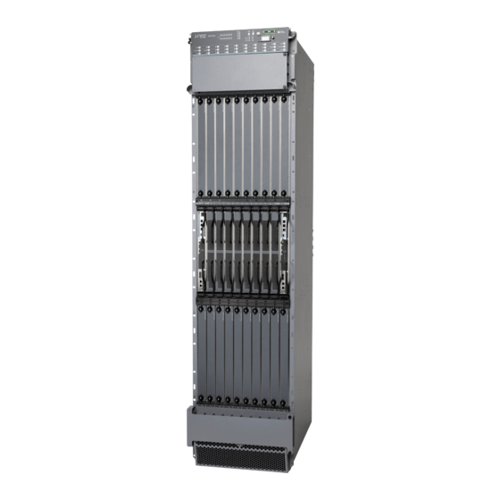
The MX2020 router is 45 rack units (U) tall. One router can be installed in a four-post rack or cabinet. The MX2020 router has 20 dedicated line card slots for a maximum of 20 Modular Port Concentrators (MPCs). -
Page 30: Mx Series Router Architecture
MX2020 Power Subsystem Description | 91 MX2020 Cooling System Description | 45 MX Series Router Architecture The key components of the Juniper Networks MX Series 5G Universal Routing Platforms are: Dense Port Concentrators (DPC) Modular Port Concentrators (MPC) Modular Interface Cards (MIC) - Page 31 Ethernet aggregation at the campus/enterprise edge—Supports dense 1-Gigabit Ethernet, 10-Gigabit Ethernet, and 100-Gigabit Ethernet configurations, and provides full Layer 3 support for campus edge requirements Ethernet aggregation at the multiservice edge—Supports up to 480 1-Gigabit Ethernet ports or 48 10-Gigabit Ethernet ports for maximum Ethernet density along, with full Layer 2 and Layer 3 VPN support for MSE applications NOTE: You can configure MX Series routers to provide simultaneous support for Layer 2 and...
-
Page 32: Mx2020 Chassis Description
10). The chassis installs in a standard 19-in. four-post rack or enclosed cabinet. NOTE: There must be a minimum of 45-U of usable rack space when installing the MX2020 router into a 45-U rack. NOTE: If you are installing the MX2020 router into a network cabinet, make sure that no hardware, device, rack, or cabinet component obstructs the 45-U rack space from access during installation. - Page 33 M X2 ONLI OFFL Remove field replacement units (FRUs) from the front of the MX2020 router before you install the router. Table 3 on page 7 for information on MX2020 router components. Table 3: Front Components in a Fully Configured MX2020 Router Component No.
- Page 34 A combination middle cable manager and air filter is installed over the middle card cage. Figure 2: Rear View of a Fully Configured AC-Powered MX2020 Router Chassis Remove field replacement units (FRUs) from the rear of the MX2020 router before you install the router. Table 4 on page 9...
- Page 35 Table 4: Rear Components in a Fully Configured AC-Powered MX2020 Router Component No. Component Description Slots Number of FRUs Upper fan trays (two) Fan tray 2 and fan tray 3 (behind cage door) AC PDM—Three-phase delta PDM3/Input1 or wye AC PSM...
- Page 36 Figure 3: Rear View of a Fully Configured DC-Powered MX2020 Router Chassis Remove field replacement units (FRUs) from the rear of the MX2020 router before you install the router. Table 5 on page 10 for information on MX2020 router components.
- Page 37 (behind access door) The MX2020 router has four electrostatic discharge (ESD) points. Two are located on either side of the upper MPCs on the front of the chassis. A second pair is located on either side of the lower MPCs on the...
-
Page 38: Mx2020 Backplane Description
MX2020 Physical Specifications | 125 Installing the MX2020 Mounting Hardware for a Four-Post Rack or Cabinet | 239 MX2000 Router Grounding Specifications | 138 MX2020 Chassis Moving Guidelines | 141 MX2020 Backplane Description Backplanes are located toward the rear of the chassis and form the rear of the card cage. They consist of one upper signal and power backplane located at the top of the chassis, and one lower signal and power backplane located at the bottom of the chassis. -
Page 39: Mx2020 Component Redundancy
PSMs may be required to supply power to a fully configured router. In a fully configured MX2020 router with 18 PSMs, the nine PSMs in the upper card cage and the nine PSMs in the lower card cage supply power to:... - Page 40 Some FRUs draw power only from zone 0, some FRUs draw power only from zone 1, and some FRUs draw power from both zone 0 and zone 1. There are two types of DC power subsystems available for the MX2020: a “base” DC power subsystem (MX2020-BASE-DC) and an “optimized” or premium DC power subsystem (MX2020-PREMIUM2-DC).
- Page 41 Figure 7: Power Distribution in an Optimized DC Power Subsystem DC PSMs—The MX2020 DC PSMs (-48 V) and DC PSMs (240 V China) are hot-removable and hot-insertable. The DC PSMs are a dual redundant feed (INP0 and INP1). To provide feed redundancy, you can connect each DC PSM to two separate feeds from different sources.
- Page 42 (INP0 and INP1). One input feed is active during operation. These feeds are set by the input mode DIP switch located on the AC PSM (see MX2020 AC Power Supply Module Description). Each AC PSM works with a single phase derived from either three-phase delta 200-240 VAC (line-to-line) or three-phase wye 200-240 VAC (line-to-neutral).
- Page 43 three-phase feeds to be connected. Each phase from each of the two feeds is distributed among one or two PSMs. One feed has each phase going to two PSMs, and the other feed has each phase going to a single PSM. The single-phase AC PDM provides an AC input connection from the single-phase AC power source, and also provides an input power interface to the PSM through a system power midplane.
- Page 44 PSM. Cooling system—The cooling system in a fully-configured MX2020 router has a total of four fan trays, which are controlled by the host subsystem. If one of the fans fails, the host subsystem increases the speed of the remaining fans to provide sufficient cooling for the router.
-
Page 45: Mx2020 Field-Replaceable Units
MX2000 Three-Phase Wye AC Power Distribution Module Description | 98 MX2000 Three-Phase Delta AC Power Distribution Module Description | 96 MX2020 DC Power Distribution Module (-48 V) Description | 107 MX2000 DC Power Distribution Module (240 V China) Description | 109... - Page 46 Related Documentation. RELATED DOCUMENTATION Replacing an MX2000 DC Power Distribution Module (-48 V) | 390 Replacing an MX2000 DC Power Distribution Module (240 V China) | 396 Replacing an MX2020 Three-Phase Wye AC Power Distribution Module | 372...
-
Page 47: Mx Series Router Packet Forwarding Engine (Pfe) Architecture
Replacing an MX2000 Three-Phase Delta AC Power Distribution Module | 359 Taking an MX2000 Host Subsystem Offline | 664 Replacing the MX2020 Cable Managers | 616 Tools and Parts Required for Replacing MX2020 Hardware Components | 355 Replacing the MX2020 Craft Interface Replacing an MX2020 Fan Tray | 437... -
Page 48: Line Cards Supported On Mx Series Routers
Switch Fabric Boards (SFB, SFB2, SFB3) | 24 Switch Control Boards | 25 MX2000 ADC | 25 Routing Engines and CB-REs | 25 Juniper Networks MX Series 5G Universal Routing Platforms process incoming and outgoing packets using: Flexible PIC Modular Port Concentrator... -
Page 49: Fpcs And Pics
Flexible PIC Modular Port Concentrator Concentrator (FPC) with (MPC) with a Switch Control Board Dense Port Physical Interface Modular Interface (SCB, SCBE, SCBE2, Concentrator (DPC) Card (PIC) Card (MIC) SCBE3) Maximum Supported on MX960 Maximum Supported on MX480 Maximum Supported on MX240 Configuration Syntax type-fpc/pic/port... -
Page 50: Mpcs And Mics
Switch Fabric Boards (SFBs) provide increased fabric bandwidth per slot. Up to eight SFBs, SFB2s, or SFB3s can be installed in an MX2020 or MX2010 router. The SFBs install vertically into the front of the chassis in the slots labeled 0 through 7. -
Page 51: Switch Control Boards
MX2010 and MX2020 routers— 8 SCBs MX2000 ADC The MX2000 ADC is a special line card adapter (ADC) that enables MX2010 and MX2020 routers to use smaller form-factor MPCs (MPC1E, MPC2E, and MPC3E). The ADC is merely a shell that accepts line cards in the front and converts power and switch fabric in the rear. -
Page 52: Ethernet Frame Counts And Statistics On Mx Series Routers
Ethernet Frame Counts and Statistics on MX Series Routers | 26 Ethernet Frame Counts and Statistics on MX Series Routers The following considerations apply to Ethernet frame counts and statistics on Juniper Networks MX Series 5G Universal Routing Platforms: Interface counters do not include the 7-byte Ethernet frame preamble and the frame delimiter byte. - Page 53 Table 8: MX2020 Router Hardware Components and CLI Terminology (continued) Hardware Model Component Number CLI Name Description DC Optimized MX2020-PREMIUM2-DC Power Chassis Craft interface MX2020-CRAFT Front Panel Display “MX2020 Craft Interface panel Description” on page 31 Extended craft MX2K-FPD-KIT-S “MX2020 Craft Interface interface panel Description”...
- Page 54 Table 8: MX2020 Router Hardware Components and CLI Terminology (continued) Hardware Model Component Number CLI Name Description PDM blank cover MX2000-PDM-BLANK “MX2020 DC Power Distribution Module (-48 Power MX2000-PDM-DC DC 52V Power Dist V) Description” on page 107 distribution Module...
- Page 55 Table 8: MX2020 Router Hardware Components and CLI Terminology (continued) Hardware Model Component Number CLI Name Description MX Series Interface Module Reference “MX2000 Modular Interface Card (MIC) Description” on page 65 MPC blank cover MX2000-LC-BLANK “MX2020 Modular Port Concentrator (MPC) Description”...
-
Page 56: Understanding Trio Layer 2 Feature Parity
Understanding Trio Layer 2 Feature Parity A variety of Layer 2 features are supported on M Series and MX Series routers. The features supported by the Trio family of line cards are listed in Table 9 on page Table 9: Trio Layer 2 Feature Parity Feature Parity with Feature Supported Feature... -
Page 57: Alarm And Display Components
Alarm and Display Components IN THIS CHAPTER MX2020 Craft Interface Description | 31 MX2020 Alarm Relay Contacts on the Craft Interface | 33 MX2020 Alarm LEDs and Alarm Cutoff/Lamp Test Button | 34 MX2020 Craft Interface Description The craft interface allows the user to view status and troubleshooting information at a glance and to perform many system control functions. - Page 58 There are three LEDs per Routing Engine. RE1 (MASTER, ONLINE, and OFFLINE) MINOR ALARM Minor Alarm LED for monitoring or maintaining the MX2020 MAJOR ALARM Major Alarm LED for critical conditions, that can result in system shutdown ACO/LT Alarm Cutoff/ Lamp Test Button. Turns off both...
-
Page 59: Mx2020 Alarm Relay Contacts On The Craft Interface
RELATED DOCUMENTATION Replacing the MX2020 Craft Interface MX2020 Craft Interface Serial Number Label | 717 MX2020 Alarm Relay Contacts on the Craft Interface The craft interface has two alarm relay contacts for connecting the router to external alarm devices. (see... -
Page 60: Mx2020 Alarm Leds And Alarm Cutoff/Lamp Test Button
RELATED DOCUMENTATION Disconnecting the Alarm Relay Wires from the MX2020 Craft Interface | 343 Connecting the Alarm Relay Wires to the MX2020 Craft Interface | 342 MX2020 Alarm LEDs and Alarm Cutoff/Lamp Test Button Two large alarm LEDs are located at the upper right of the craft interface. - Page 61 Causes all LEDs on the craft interface to light (for testing) when pressed and held. RELATED DOCUMENTATION MX2020 Craft Interface Description | 31 MX2020 Alarm Relay Contacts on the Craft Interface | 33 MX2020 Universal Edge Router Overview | 3...
-
Page 62: Cable And Rack Management
IN THIS SECTION Standard Cable Management System | 37 Extended Cable Management System | 40 The MX2020 consists of a standard or extended cable management system. Standard Cable Management System The standard cable management system consists of the following components: Upper cable manager—MX2000-CBL-TOP-S... - Page 63 You can pull the DC cable manager up and outward to lock it into the maintenance position. Figure 14: MX2020 Standard Cable Managers Front top Front bottom...
- Page 64 Figure 15: Upper and Lower Cable Management The middle card-cage cable manager, (see Figure 16 on page 40 Figure 17 on page 40) is a combination cable tray and air filter located in the middle card cage, which has rows for routing and securing the cables away from the front of the CB-REs, and SFBs.
-
Page 65: Extended Cable Management System
Figure 16: Middle Card-Cage Cable Manager Figure 17: Middle Card-Cage Air Filter Extended Cable Management System The extended cable management system consists of the following components: Extended upper cable manager—MX2000-CBL-TOP-XT-S Extended lower cable manager—MX2000-CBL-BTM-XT-S... - Page 66 You can use cable strips or other ties to gently secure the cables in the upper and lower extended cable managers. To secure the cables in place, loop the tie through the cable anchor and secure the tie. Figure 18: MX2020 Extended Cable Managers Front upper...
-
Page 67: Mx2020 Rack-Mounting Hardware
Figure 19: Upper and Lower Extended Cable Management RELATED DOCUMENTATION Installing the MX2020 Upper Cable Manager | 621 Installing the MX2020 Lower Cable Manager | 620 Installing the MX2020 DC Cable Manager | 615 Replacing the MX2020 Cable Managers | 616... - Page 68 NOTE: There must be a minimum of 45 U of usable rack space when installing the MX2020 router into a 45-U rack. RELATED DOCUMENTATION MX2020 Chassis Description | 6 MX2020 Backplane Description | 12 Installing the MX2020 Mounting Hardware for a Four-Post Rack or Cabinet | 239...
-
Page 69: Cooling System Components And Descriptions
CHAPTER 4 Cooling System Components and Descriptions IN THIS CHAPTER MX2020 Cooling System Description | 45 MX2020 Fan Tray LED | 48 MX2020 Cooling System Description The cooling system consists of the following components: Base Fan Tray (MX2000-FANTRAY) or Optimized Power Fan tray (MX2K-FANTRAY-OP-S) Lower Fan Tray Air filter—MX2020-FLTR-KIT-S... - Page 70 Card cage Lower fan trays The MX2020 router provides a two-stage front-to-back cooling system. Air is pushed into the bottom inlet and up through the lower fan tray, and exits through the opening between the backplanes in the center of the chassis. This cools the bottom MPCs, half of the SFBs and CB-REs. Air is pulled through the...
- Page 71 Figure 23: Lower Fan Tray Air Filter The air baffle is an optional component that can be purchased from Juniper Networks. When installed over the upper fan tray access door, the air baffle dissipates exhausted air away from the router.
-
Page 72: Mx2020 Fan Tray Led
Table 13 on page 48). A set of four bicolor fan tray LEDs is located on the top middle of the craft interface. For more information, see MX2020 Component LEDs on the Craft Interface. Table 13: Fan Tray LEDs Label... -
Page 73: Host Subsystem Components
CHAPTER 5 Host Subsystem Components IN THIS CHAPTER MX2000 Host Subsystem CB-RE Description | 49 RE-MX2000-1800x4 CB-RE Description | 50 REMX2K-X8-64G and REMX2K-X8-64G-LT CB-RE Description | 54 CB-RE LEDs | 56 REMX2K-X8-128G CB-RE Description | 60 MX2000 Switch Fabric Board (SFB) Overview | 63 MX2000 Host Subsystem CB-RE Description The CB-RE is a combined Routing Engine and Control Board in one unit. -
Page 74: Re-Mx2000-1800X4 Cb-Re Description
RE-MX2000-1800x4 CB-RE Description | 50 REMX2K-X8-64G and REMX2K-X8-64G-LT CB-RE Description | 54 Maintaining the MX2010 Host Subsystem Maintaining the MX2020 Host Subsystem Taking an MX2000 Host Subsystem Offline | 664 RJ-45 Connector Pinouts for MX Series CB-RE or RCB Auxillary and Console Ports... -
Page 75: Re-Mx2000-1800X4 Cb-Re Front Panel
RE-MX2000-1800x4 CB-RE Front Panel Figure 24 on page 51 shows the Control Board and Routing Engine (CB-RE)—RE-MX2000-1800x4. Table 14 on page 51 describes the Control Board and Routing Engine (CB-RE)—RE-MX2000-1800x4 ports. Figure 24: RE-MX2000-1800x4 CB-RE Front View ONLINE OFFLINE CONSOLE MGMT RESET Table 14: Components on the RE-MX2000-1800x4... -
Page 76: Re-Mx2000-1800X4 Cb-Re Components
There is one bicolor LED for each external clock interface—BITS and GPS. XGE-0 and XGE-1 These ports are used for hardware diagnostics and are for Juniper-internal use only. ONLINE, MASTER, and There is one bicolor LED for each CB-RE OK/FAIL control. -
Page 77: Re-Mx2000-1800X4 Cb-Re Software
The two ports labeled XGE-0 and XGE-1 are used for hardware diagnostics and are for Juniper-internal use only. The ExtClk ports provide access to external timing distribution. EEPROM—Stores the serial number of the CB-RE. -
Page 78: Remx2K-X8-64G And Remx2K-X8-64G-Lt Cb-Re Description
REMX2K-X8-64G and REMX2K-X8-64G-LT CB-RE Description IN THIS SECTION REMX2K-X8-64G CB-RE Components | 54 REMX2K-X8-64G and REMX2K-X8-64G-LT CB-RE Boot Sequence | 56 REMX2K-X8-64G CB-RE Components Figure 25: REMX2K-X8-64G CB-RE Components CONSOLE MGMT ONLINE LINK DISK1 BITS DISK2 RE-MX2K-X8-64G XGE-0 XGE-1 EXTCLK-0 EXTCLK-1 OK/FAIL AUX port... - Page 79 Each Control Board-Routing Engine (CB-RE) consists of the following components: External clock interface—Allows BITS or GPS clock source input to the centralized timing circuit, or allows centralized timing to be output to BITS or GPS. 1000Base-T Ethernet controller. Circuits for chassis management and control. Power circuits for the CB-RE.
-
Page 80: Remx2K-X8-64G And Remx2K-X8-64G-Lt Cb-Re Boot Sequence
REMX2K-X8-64G and REMX2K-X8-64G-LT CB-RE Boot Sequence The router is shipped with Junos OS and Linux preinstalled on the CB-RE. There are two copies of software: One copy on a USB flash drive that can be inserted into the slot on the CB-RE faceplate. One copy each on the two SSDs in the CB-RE. - Page 81 Table 15: CB-RE LEDs Label Color State Description ONLINE Green Blinking CB-RE is transitioning online. CB-RE is functioning normally. steadily — CB-RE is offline. MASTER Blue CB-RE is the master. steadily OK/FAIL CB-RE has failed. steadily LINK Green SFP+ ports (XGE-0 and XGE-1) link connection. steadily Blinking Activity on SFP+ ports (XGE-0 and XGE-1).
- Page 82 Figure 27: REMX2K-X8-64G CB-RE LEDs Table 16: REMX2K-X8-64G CB-RE LEDs Callout from F i g u r e 2 7 o n p a g e 5 8 Label Color State Description ONLINE Green Blinking CB-RE is transitioning online. CB-RE is functioning normally. steadily —...
- Page 83 UTI external clocking interface has failed. steadily – UTI external clocking interface is offline. OK/FAIL CB has failed. steadily RELATED DOCUMENTATION MX2000 Host Subsystem CB-RE Description | 49 Maintaining the MX2020 Host Subsystem | 485 Taking an MX2000 Host Subsystem Offline | 664...
-
Page 84: Remx2K-X8-128G Cb-Re Description
REMX2K-X8-128G CB-RE Description IN THIS SECTION REMX2K-X8-128G CB-RE Components | 60 REMX2K-X8-128G CB-RE LEDs | 62 REMX2K-X8-128G CB-RE Boot Sequence | 63 The Routing Engine is equipped with a 8-Core 2.3 GHz processor, 128 GB memory, and 200 GB SSDs and also supports Secure Boot for enhanced boot security. - Page 85 CPU—Runs Junos OS as a guest OS to maintain the router's routing tables and routing protocols. I2C bus logic, used for low-level communication with each component. DRAM—Provides storage for the routing and forwarding tables and for other Routing Engine processes. Component redundancy circuitry.
-
Page 86: Remx2K-X8-128G Cb-Re Leds
REMX2K-X8-128G CB-RE LEDs Figure 29: REMX2K-X8-128G CB-RE LEDs CONSOLE MGMT LINK ONLINE DISK1 BITS DISK2 REMX2K-X8-128G XGE-0 XGE-1 EXTCLK-0 EXTCLK-1 OK/FAIL REMX2K-X8-128G ONLINE LED, OK/FAIL LED, and MASTER LED BITS, GPS, and UTI LEDs — — DISK1 and DISK2 LEDs ONLINE/OFFLINE button —... -
Page 87: Remx2K-X8-128G Cb-Re Boot Sequence
REMX2K-X8-128G CB-RE Boot Sequence The router is shipped with Junos OS and Linux preinstalled on the CB-RE. There are two copies of software: One copy on a USB flash drive that can be inserted into the slot on the CB-RE faceplate. One copy each on the two SSDs in the CB-RE. -
Page 88: Interface Modules- Adcs, Mpcs, And Mics
MX2000 Modular Interface Card (MIC) Description | 65 MICs Supported by MX Series Routers | 66 MX2020 Modular Interface Card LEDs | 76 MX2020 Modular Port Concentrator (MPC) Description | 76 MPCs Supported by MX Series Routers | 79 MX2020 Modular Port Concentrator LEDs | 83... -
Page 89: Mics Supported By Mx Series Routers
Junos OS release for MICs on MX240, MX480, MX960, and MX2008 routers. Table 19 on page 69 lists the first supported Junos OS release for MICs on MX2010 and MX2020 routers. Table 20 on page 72 list the first supported Junos OS release for MICs on MX5, MX10, and MX40 routers. - Page 90 Table 18: MICs Supported by MX240, MX480, MX960 and MX2008 Routers (continued) MX240, MX480, and MX2008 MIC Name MIC Model Number Ports MX960 Routers Routers Gigabit Ethernet MIC with SFP MIC-3D-20GE-SFP-E 13.3 15.1F7 Gigabit Ethernet MIC with MIC-MACSEC-20GE 18.3 256b-AES MACSEC 10-Gigabit Ethernet 10-Gigabit Ethernet MICs with MIC-3D-2XGE-XFP...
- Page 91 Table 18: MICs Supported by MX240, MX480, MX960 and MX2008 Routers (continued) MX240, MX480, and MX2008 MIC Name MIC Model Number Ports MX960 Routers Routers 100-Gigabit Ethernet MIC with MIC6-100G-CFP2 15.1F7 CFP2 100-Gigabit DWDM OTN 100-Gigabit DWDM OTN MIC MIC3-100G-DWDM 15.1F5 15.1F7 with CFP2-ACO...
- Page 92 Services Multiservices MIC MS-MIC-16G 13.2 15.1F7 SONET/SDH SONET/SDH OC192/STM64 MIC-3D-1OC192-XFP 12.2 15.1F7 MIC with XFP Table 19: MICs Supported by MX2010 and MX2020 Routers MX2010 MX2020 MIC Name MIC Model Number Ports Routers Routers ATM MIC with SFP MIC-3D-8OC3-2OC12-ATM 12.3 12.3...
- Page 93 Table 19: MICs Supported by MX2010 and MX2020 Routers (continued) MX2010 MX2020 MIC Name MIC Model Number Ports Routers Routers 10-Gigabit Ethernet MICs with MIC-3D-4XGE-XFP 12.3 12.3 10-Gigabit Ethernet MIC with MIC3-3D-10XGE-SFPP 12.3 12.3 SFP+ (10 Ports) 10-Gigabit Ethernet MIC with MIC6-10G 13.3R2...
- Page 94 Table 19: MICs Supported by MX2010 and MX2020 Routers (continued) MX2010 MX2020 MIC Name MIC Model Number Ports Routers Routers SONET/SDH OC3/STM1 MIC-3D-8OC3OC12-4OC48 12.3 12.3 (Multi-Rate) MICs with SFP Channelized SONET/SDH MIC-3D-4CHOC3-2CHOC12 12.3 12.3 OC3/STM1 (Multi-Rate) MICs with SFP Channelized SONET/SDH MIC-3D-8CHOC3-4CHOC12 12.3...
- Page 95 Table 20: MICs Supported by MX5, MX10, and MX40 Routers MIC Name MIC Model Number Ports MX10 MX40 ATM MIC with SFP MIC-3D-8OC3-2OC12-ATM 12.1 12.1 12.1 DS3/E3 DS3/E3 MIC MIC-3D-8DS3-E3, 11.4 11.4 11.4 MIC-3D-8CHDS3-E3-B Circuit Emulation Channelized E1/T1 Circuit MIC-3D-16CHE1-T1-CE 13.2R2 13.2R2 13.2R2...
- Page 96 Table 20: MICs Supported by MX5, MX10, and MX40 Routers (continued) MIC Name MIC Model Number Ports MX10 MX40 Channelized SONET/SDH MIC-3D-4CHOC3-2CHOC12 11.4 11.4 11.4 OC3/STM1 (Multi-Rate) MICs with SFP Channelized SONET/SDH MIC-3D-8CHOC3-4CHOC12 11.4 11.4 11.4 OC3/STM1 (Multi-Rate) MICs with SFP Channelized OC3/STM1 MIC-3D-4COC3-1COC12-CE 12.2...
- Page 97 Table 21: MICs Supported by MX80 and MX104 Routers (continued) MIC Name MIC Model Number Ports MX80 MX104 Circuit Emulation Channelized E1/T1 Circuit MIC-3D-16CHE1-T1-CE 13.2R2 13.2R2 Emulation MIC Channelized E1/T1 Circuit MIC-3D-16CHE1-T1-CE-H – 13.2R2 Emulation MIC (H) Gigabit Ethernet Gigabit Ethernet MIC with SFP MIC-3D-20GE-SFP 10.2 13.2R2...
- Page 98 Table 21: MICs Supported by MX80 and MX104 Routers (continued) MIC Name MIC Model Number Ports MX80 MX104 Channelized OC3/STM1 MIC-3D-4COC3-1COC12-CE 12.2 13.2R2 (Multi-Rate) Circuit Emulation MIC with SFP Channelized OC3/STM1 MIC-4COC3-1COC12-CE-H 13.2R2 (Multi-Rate) Circuit Emulation MIC with SFP (H) Tri-Rate Tri-Rate MIC MIC-3D-40GE-TX...
-
Page 99: Mx2020 Modular Interface Card Leds
RELATED DOCUMENTATION MX2000 Modular Interface Card (MIC) Description | 65 Maintaining MX2020 MICs | 525 Troubleshooting the MX2020 MICs | 681 Replacing an MX2020 MIC | 553 MX2020 Modular Port Concentrator (MPC) Description Designed for flexibility, MX2000 Modular Port Concentrators (MPCs) leverage the Junos Trio chipset to deliver the industry’s highest Gigabit Ethernet density, as well as the flexibility of modular interfaces across... - Page 100 Each MPC is equipped with up to four Junos Trio chipsets, which perform control functions tailored to the MPC’s media type. The MX2020 router supports up to 20 MPCs. For power requirements, see Calculating DC Power Requirements for MX2020 Routers and “Calculating AC Power Requirements for MX2020 Routers”...
-
Page 101: Mpc Components
Figure 31: MPC Installed in the MX2020 Router MPC Components Each MPC consists of the following components: MIC card carrier, which includes two MIC slots (excludes the fixed configuration MPC). Fabric interfaces. Two Gigabit Ethernet interfaces that allow control information, route information, and statistics to be sent between the routing engine and the CPU on the MPCs. -
Page 102: Mpcs Supported By Mx Series Routers
Table 23 on page 79 lists the MPCs and their first supported Junos OS release on MX240, MX480, MX960, MX2008, MX2010, MX2020, and MX10003 routers. Table 23: MPCs Supported by MX240, MX480, MX960, MX2008, MX2010, MX2020, and MX10003 Routers First Junos OS... - Page 103 Table 23: MPCs Supported by MX240, MX480, MX960, MX2008, MX2010, MX2020, and MX10003 Routers (continued) First Junos OS Release First Junos First First First First MX240, Junos OS Junos OS Junos OS Junos OS MX480, Release Release Release Release Release...
- Page 104 Table 23: MPCs Supported by MX240, MX480, MX960, MX2008, MX2010, MX2020, and MX10003 Routers (continued) First Junos OS Release First Junos First First First First MX240, Junos OS Junos OS Junos OS Junos OS MX480, Release Release Release Release Release...
- Page 105 Table 23: MPCs Supported by MX240, MX480, MX960, MX2008, MX2010, MX2020, and MX10003 Routers (continued) First Junos OS Release First Junos First First First First MX240, Junos OS Junos OS Junos OS Junos OS MX480, Release Release Release Release Release...
-
Page 106: Mx2020 Modular Port Concentrator Leds
MX2020 Modular Port Concentrator LEDs One bicolor LED located on the craft interface above the MPC, displays the status of the MPC. For more information about the MPC LEDs on the craft interface, see MX2020 Component LEDs on the Craft Interface. -
Page 107: Mx2000 Adapter Card (Adc) Description
MX2020 Modular Port Concentrator (MPC) Description | 76 Maintaining MX2020 MPCs | 521 Troubleshooting a Modular Port Concentrator (MPC) | 683 Replacing an MX2020 MPC and Adapter Card (ADC) | 536 MICs Supported by MX Series Routers | 66 MX2000 Adapter Card (ADC) Description The MX2000 routers are compatible with all Trio-based MPC line cards;... -
Page 108: Mpc Terminology
Figure 32: ADC for the MX2000 Routers OK/FAI RELATED DOCUMENTATION Maintaining the MX2010 Adapter Cards Maintaining MX2020 Adapter Cards | 551 MPCs Supported by MX Series Routers | 79 Replacing an MX2008 MPC MPC Terminology Regardless of whether you are holding an MPC vertically or horizontally, this information uses the same... - Page 109 RELATED DOCUMENTATION MX2020 Modular Port Concentrator (MPC) Description | 76 MX2020 Component LEDs on the Craft Interface Holding an MPC | 533 Troubleshooting a Modular Port Concentrator (MPC) | 683 Replacing an MX2020 MPC and Adapter Card (ADC) | 536...
-
Page 110: Mx2020 Port And Interface Numbering
Ethernet interface For a complete list of media types, see Interface Naming Overview. fpc—Slot in which the MPC is installed. On the MX2020 router, the MPCs are represented in the CLI as FPC 0 through FPC 19. pic—Logical PIC on the MIC. The number of logical PICs varies depending on the type of MIC. - Page 111 Xcvr 1 REV 01 740-011782 PAR1L27 SFP-SX Xcvr 2 REV 01 740-011613 PDQ4XH4 SFP-SX Xcvr 4 REV 02 740-011613 AM1113SK1K7 SFP-SX Xcvr 5 REV 01 740-011782 P9P0XXH SFP-SX Xcvr 6 REV 02 740-011613 PJT1CSS SFP-SX Xcvr 7 REV 01 740-011782 PAR1YHC SFP-SX Xcvr 8...
- Page 112 Figure 34: MX2020 Interface Port Mapping MIC-3D-4XGE-XFP MIC 0 PORT [0/2]0 xe-19/0/0 PORT [0/2]1 xe-19/0/1 PORT [1/3]0 xe-19/1/0 PORT [1/3]1 xe-19/1/1 MIC-3D-20GE-SFP ge-19/2/0 ge-19/3/0 ge-19/2/1 ge-19/3/1 ge-19/2/2 ge-19/3/2 ge-19/2/3 ge-19/3/3 ge-19/2/4 ge-19/3/4 ge-19/2/5 ge-19/3/5 ge-19/2/6 ge-19/3/6 ge-19/2/7 ge-19/3/7 ge-19/2/8 ge-19/3/8...
- Page 113 RELATED DOCUMENTATION MX2020 Router Hardware Components and CLI Terminology | 26...
-
Page 114: Power Subsystem
AC power configurations, and a single-phase power configuration. You can add additional power to the rack as needed. The MX2020 router is configurable with up to four AC or DC power distribution modules (PDMs) (two per subsystem), and up to eighteen AC or DC power supply modules (PSMs). The PSMs connect to the top and bottom power backplanes that distribute the output voltages produced by the PSMs to the router components. - Page 115 MPCs will stop functioning; the router will continue to function. There are two types of DC power subsystems available for the MX2020: a “base” DC power subsystem (MX2020-BASE-DC) and an “optimized” or premium DC power subsystem (MX2020-PREMIUM2-DC).
- Page 116 Each DC PDM (240 V China) operates with nine feeds. DC Power Supply Modules (PSMs) The MX2020 DC PSMs (-48 V and 240 V China) are hot-removable and hot-insertable. The DC PSMs are a dual redundant feed (INP0 and INP1).
- Page 117 200-240 VAC (line-to-line) or three-phase wye 200-240 VAC (line-to-neutral). Each AC PSM is capable of delivering 2500 W of power. The MX2020 router supports the power system models and Junos OS releases in Table 26 on page Table 26: Supported MX2020 Power System Components...
- Page 118 NOTE: To avoid triggering any PSM-related or power-related alarms for the PSMs that are not used but still plugged into the MX2020 router, make sure that you: Do not connect external power feeds to the PSM through the PDM. Move the DIP switch on the PSMs to the off position.
-
Page 119: Mx2020 Power Midplane Description
MX2020 Power Midplane Description The MX2020 power subsystem consists of a power midplane (PMP). This midplane is used to connect power from the PDM feeds (AC or DC) to the input of the PSMs (AC or DC) as well as the output from the PSMs to the FRUs (MPCs, CB-REs, SFBs, and Fan Trays). - Page 120 Figure 35: Three-Phase Delta AC Power Distribution Module Figure 36 on page 97 shows the three-phase delta AC PDM connections. CAUTION: The three-phase delta AC PDM must be installed and secured in the chassis before connecting the power input cables. If the PDM must be removed, both input power cables must be uninstalled and removed from the PDM before the PDM can be removed from the chassis.
-
Page 121: Mx2000 Three-Phase Wye Ac Power Distribution Module Description
Figure 37: Three-Phase Delta AC Power Cord RELATED DOCUMENTATION MX2010 Power System Description MX2020 Power Subsystem Description | 91 Maintaining the Power Supply Modules on the MX2000 Line of Routers | 418 Troubleshooting the MX2000 Router Power System | 686... - Page 122 NOTE: The three-phase wye AC PDM terminal blocks will be flipped depending on which slot the PDM gets plugged into. Figure 38: Three-Phase Wye AC Power Distribution Module Figure 39 on page 100 shows the three-phase wye AC PDM connections. CAUTION: The three-phase wye AC PDM must be installed and secured in the chassis before connecting the power input cables.
- Page 123 Figure 39: Three-Phase Wye AC Power Distribution Module Connections Figure 40 on page 100 shows the three-phase wye AC power cord. Figure 40: Three-Phase Wye AC Power Cord RELATED DOCUMENTATION...
-
Page 124: Mx2000 Seven-Feed Single-Phase Ac Power Distribution Module Description
MX2010 Power System Description MX2020 Power Subsystem Description | 91 Maintaining the Power Supply Modules on the MX2000 Line of Routers | 418 Troubleshooting the MX2000 Router Power System | 686 MX2020 AC Power Requirements | 167 MX2010 AC Power Requirements... -
Page 125: Mx2000 Nine-Feed Single-Phase Ac Power Distribution Module Description
Troubleshooting the MX2000 Router Power System | 686 MX2020 AC Power Requirements | 167 MX2000 Nine-Feed Single-Phase AC Power Distribution Module Description The MX2000 nine-feed single-phase AC power distribution module (PDM) provides AC input connection from a single-phase AC source, and also provides an input power interface to the power supply module (PSM) through a system power midplane. -
Page 126: Mx2000 Three-Phase Delta And Wye Ac Power Distribution Module Leds
MX2020 AC Power Requirements | 167 MX2020 Power Subsystem Description | 91 MX2000 Three-Phase Delta and Wye AC Power Distribution Module LEDs Figure 43 on page 103 shows the LEDs on the three-phase delta AC PDM faceplate. The three-phase wye AC PDM has the same LEDs. - Page 127 fan trays (0, 1, 2, and 3; 0 and 1 for MX2008) MPCs in slot 0 through 9 CB-REs in slot 0 and 1 SFBs in slot 0 through 7 The MX2000 line of routers supports a three-phase delta AC power system, three-phase wye AC power system, or a single-phase AC power system.
- Page 128 Figure 44: AC Power Supply Module The AC power system provides dual redundant feeds (INP0 and INP1). Each PSM takes in two AC feeds and uses one of the two. One input feed is active during operation. Each feed is a single-phase AC system 200–240 VAC derived from a three-phase delta or wye AC input system.
-
Page 129: Mx2020 Ac Power Supply Module Leds
“MX2000 AC Power System Electrical Specifications” on page 179. RELATED DOCUMENTATION MX2020 AC Power Supply Module LEDs | 106 MX2020 AC Power Supply Module LEDs Each AC PSM faceplate contains four LEDs. These LEDs are described in Table 29 on page 107. -
Page 130: Mx2020 Dc Power Distribution Module (-48 V) Description
MX2020 DC Power Distribution Module (-48 V) Description In the DC power configuration, the MX2020 router contains up to four DC PDMs located at the rear of the chassis in slots PDM0/Input0 through PDM3/Input1 (bottom to top). A minimum of one PDM is required per subsystem (two PDMs per MX2020 chassis) for nonredundant power. - Page 131 2800 W. The system power management software calculates the available and used power based on DIP switch positions in the PDM. RELATED DOCUMENTATION MX2020 DC Power Distribution Module (-48 V) LEDs | 110 MX2000 Router Grounding Specifications | 138 Calculating DC Power Requirements for MX2020 Routers...
-
Page 132: Mx2000 Dc Power Distribution Module (240 V China) Description
China) located at the rear of the chassis in slots PDM0/Input0 through PDM3/Input1 (bottom to top). A minimum of one PDM is required per subsystem (two PDMs per MX2020 chassis) for nonredundant power. The DC PDMs provide power interface to nine power supply modules (PSMs). -
Page 133: Mx2020 Dc Power Distribution Module (-48 V) Leds
MX2000 Router DC (240 V China) Power Subsystem Electrical Specifications | 207 Site Electrical Wiring Guidelines for MX Series Routers MX2020 DC Power Distribution Module (-48 V) LEDs Each DC PDM faceplate contains one bicolor LED for each of the seven or nine input power feeds (–48 V), indicating the correct or incorrect polarity connection of each feed. -
Page 134: Mx2000 Dc Power Distribution Module (240 V China) Leds
MX2020 Component LEDs on the Craft Interface MX2020 Power Subsystem Description | 91 MX2020 DC Power Distribution Module (-48 V) Description | 107 MX2000 Router DC Power Subsystem Electrical Specifications | 205 MX2000 DC Power Distribution Module (240 V China) LEDs Each DC PDM (240 V China) faceplate contains one LED for each of the nine input power feeds, indicating the correct or incorrect polarity connection of each feed. -
Page 135: Mx2020Dc Power Supply Module (-48 V) Description
MX2020DC Power Supply Module (-48 V) Description The MX2020 supports a two zone DC power system. Each zone (upper and lower) is provided power by one half of the power subsystem. In the DC power configuration, the router contains up to eighteen DC PSMs located at the rear of the chassis in slots PSM0 through PSM8 (bottom), and slots PSM9 through PSM17 (top) (left to right). - Page 136 Figure 50: DC Power Supply Module The DC power subsystem is feed redundant. Each DC PSM can be connected to two separate feeds from different sources that are used to provide feed redundancy. If two feeds are connected, PSM input power will be drawn from the feed with the higher voltage present.
- Page 137 MX2020 DC and Power Supply Module LEDs | 117 MX2000 Router Grounding Specifications | 138 DC Power (-48 V) Circuit Breaker Requirements for the MX2020 Router | 215 MX2020 DC Power Distribution Description | 201 DC Power Cable Specifications for the MX2020 Router | 216...
-
Page 138: Mx2000 Dc Power Supply Module (240 V China) Description
MX2000 DC Power Supply Module (240 V China) Description The MX2020 supports a two zone DC power system. Each zone (upper and lower) is provided power by one half of the power subsystem. In the DC power configuration, the router contains up to eighteen DC PSMs located at the rear of the chassis in slots PSM0 through PSM8 (bottom), and slots PSM9 through PSM17 (top) (left to right). - Page 139 MX2000 DC Power Distribution Module (240 V China) LEDs | 111 MX2000 Router Grounding Specifications | 138 DC Power (-48 V) Circuit Breaker Requirements for the MX2020 Router | 215 MX2000 DC Power Distribution Module (240 V China) Description | 109...
-
Page 140: Mx2020 Dc And Power Supply Module Leds
The primary input of the PSM is a dual redundant feed, INP0 and INP1. Both feeds are active during operation, but both feeds may or may not be providing current. In addition, a PSM failure triggers the alarm LED on the craft interface. Table 34: MX2020 DC Power Supply Module LEDs Label Color... - Page 141 MX2020 Component LEDs on the Craft Interface MX2020 Power Subsystem Description | 91 MX2020DC Power Supply Module (-48 V) Description | 112 MX2000 DC Power Supply Module (240 V China) Description | 115 MX2000 Router DC Power Subsystem Electrical Specifications | 205...
-
Page 142: Site Planning, Preparation, And Specifications
PART Site Planning, Preparation, and Specifications Planning and Preparing the Site | 121 Transceiver and Cable Specifications | 149 Pinout Specifications | 155 AC Power Requirements, Specifications, and Guidelines | 167 DC Power Requirements, Specifications, and Guidelines | 193... -
Page 144: Planning And Preparing The Site
MX2020 Physical Specifications | 125 MX2020 Rack Requirements | 130 MX2020 Cabinet Size and Clearance Requirements | 133 Clearance Requirements for Airflow and Hardware Maintenance for the MX2020 Router | 133 MX2020 Cabinet Airflow Requirements | 136 MX2020 Router Environmental Specifications | 137... - Page 145 MX2020 DC Power Distribution (240 V China) Description on page 203 5. Plan rack location, including required space clearances. See: Clearance Requirements for Airflow and Hardware Maintenance for the MX2020 Router on page 133 MX2020 Physical Specifications on page 125 6.
-
Page 146: Mx2020 Site Preparation Checklist
Understanding Fiber-Optic Cable Signal Loss, Attenuation, and Dispersion on page 151 10. Plan the cable routing and management. See: MX2020 Cable Management Description on page 37 Maintaining Cables That Connect to MX2020 MPCs or MICs on page 529 RELATED DOCUMENTATION MX2020 Universal Edge Router Overview | 3... - Page 147 Table 35: MX2020 Site Preparation Checklist (continued) Item or Task For More Information Performed By Date Locate sites for connection of “MX2000 Router Grounding system grounding. Specifications” on page 138 Calculate the power “MX2020 AC Power consumption and Requirements” on page 167 requirements.
-
Page 148: Mx2020 Physical Specifications
Table 35: MX2020 Site Preparation Checklist (continued) Item or Task For More Information Performed By Date Acquire cables and “Understanding Fiber-Optic transceivers: Cable Signal Loss, Attenuation, and Dispersion” on page 151 Determine the number of cables needed based on “Calculating Power Budget and your planned configuration. - Page 149 Table 36: MX2020 Shipping Weight Specifications (continued) Item Shipping Weight Fully populated MX2020 with shipping crate and pallet 1,680 lb (762 kg) Table 37: MX2020 Physical Specifications Description Weight Width Depth Height Chassis Chassis with 19 in. (48.26 cm) With standard cable 78.75 in (200 cm)
- Page 150 Table 37: MX2020 Physical Specifications (continued) Description Weight Width Depth Height Blank MPC 5.4 lb (4.08 kg) 1.25 in. (3.17 cm) 22.8 in (57.91 cm) 15.5 in (39.37 cm) panel 1.2 lb (0.54 kg) 1.25 in. (3.17 cm) 6.25 in (15.9 cm) 6.8 in (17.3 cm)
- Page 151 Table 37: MX2020 Physical Specifications (continued) Description Weight Width Depth Height PSM air filter 0.5 lb (0.23 kg) 16.0 in. 5.75 in. (14.60 cm) 0.3 in. (0.76 cm) (40.64 cm) 12 lb (5.44 kg) 1.7 in. (4.31 cm) 23.6 in. (59.94 cm) 16.225 in.
- Page 152 (44.32 cm) Extended EMI 9.65 lb (4.4 kg) 17.45 in. 5.40 in. (13.7 cm) 18.86 in. (47.9 cm) cover (44.32 cm) RELATED DOCUMENTATION MX2020 Chassis Moving Guidelines | 141 MX2020 Universal Edge Router Overview | 3 MX2020 Chassis Description | 6...
-
Page 153: Mx2020 Rack Requirements
Connection to the Building Structure | 132 Rack Size and Strength The MX2020 router is designed for installation in a rack that complies with either the following standards: A 19-in. rack as defined in Cabinets, Racks, Panels, and Associated Equipment (document number EIA-310-D) published by the Electronics Components Industry Association (http://www.ecianow.org/). - Page 154 NOTE: For a complete list of chassis and component weights and measurements, see “MX2020 Physical Specifications” on page 125. NOTE: There must be a minimum of 45-U of usable rack space when installing the MX2020 router into a 45-U rack.
-
Page 155: Spacing Of Mounting Bracket Holes
Always secure the rack to the structure of the building. If your geographical area is subject to earthquakes, bolt the rack to the floor. For maximum stability, also secure the rack to ceiling brackets. RELATED DOCUMENTATION Clearance Requirements for Airflow and Hardware Maintenance for the MX2020 Router | 133... -
Page 156: Mx2020 Cabinet Size And Clearance Requirements
The minimum total clearance inside the cabinet is 36.20 in. (91.95 cm) between the inside of the front door and the inside of the rear door. NOTE: If you are installing the MX2020 router into a network cabinet, make sure that no hardware, device, rack, or cabinet component obstructs the 45-U rack space from access during installation. - Page 157 MX2020 Power Distribution Modules (PDMs), and Power Supply Modules (PSMs); they are within specification. An MX2020 router with an extended cable manager requires extra clearance to accommodate the depth of 37.46 in. (95.1 cm). Figure 55: Chassis Dimensions and Clearance Requirements for the MX2020 Router with the Standard...
- Page 158 Figure 56: Chassis Dimensions and Clearance Requirements for the MX2020 Router with the Extended Cable Manager NOTE: There must be a minimum of 45 U of usable rack space when you install the MX2020 router into a 45-U rack. RELATED DOCUMENTATION...
-
Page 159: Mx2020 Cabinet Airflow Requirements
MX2020 Cabinet Airflow Requirements Before you install the router in a cabinet, you must ensure that ventilation through the cabinet is sufficient to prevent overheating. Consider the following requirements to when planning for chassis cooling: Ensure that the cool air supply you provide through the cabinet can adequately dissipate the thermal output of the router. -
Page 160: Mx2020 Router Environmental Specifications
Airflow divider Card cage Lower fan trays RELATED DOCUMENTATION Clearance Requirements for Airflow and Hardware Maintenance for the MX2020 Router | 133 MX2020 Cabinet Size and Clearance Requirements | 133 MX2020 Rack Requirements | 130 MX2020 Rack-Mounting Hardware | 42... -
Page 161: Mx2000 Router Grounding Specifications
Articles 110-16, 110-17, and 110-18 of the National Electrical Code, ANSI/NFPA 70. RELATED DOCUMENTATION Tools and Parts Required to Maintain the MX2020 Hardware Components | 225 Definition of Safety Warning Levels MX2000 Router Grounding Specifications... -
Page 162: Mx2000 Series Chassis Grounding Points Specifications
MX2000 Series Chassis Grounding Points Specifications To meet safety and electromagnetic interference (EMI) requirements and to ensure proper operation, the router must be adequately grounded before power is connected. To ground AC-powered or DC-powered routers, you must connect a grounding cable to earth ground and then attach it to one of the chassis grounding points using the two screws provided. -
Page 163: Mx2000 Series Router Grounding Cable Specifications
NOTE: The MX2000 series routers support 4-AWG DC power cable lugs for 80-A input (see Figure 59 on page 140), and 6-AWG DC power cable lugs for 60-A input (see Figure 60 on page 140). Figure 59: 4-AWG DC Grounding Cable Lug End view Inner diameter .28 0.27... -
Page 164: Mx2020 Chassis Moving Guidelines
(194.86 kg) with components removed. Observe the following guidelines for moving the router: Before moving the router, read the “Overview of Preparing the Site for the MX2020 Router” on page 121 to verify that the intended site meets the specified power, environmental, and clearance requirements. -
Page 165: Mx2020 Moving Requirements And Guidelines Using A Router Transport Kit
Router Transport Kit Turning Radius | 142 Router Transport Kit Requirements | 143 Router Transport Kit Turning Radius The MX2020 requires a minimum 42 in. (106.7 cm) diameter of space to turn the chassis on the router transport kit (see Figure 61 on page 143. -
Page 166: Router Transport Kit Requirements
42 in (106.7 cm) The weight of the router transport kit is 138.5 lb (63 kg). The maximum recommended height the MX2020 should be lifted from the floor using the router transport kit is 1.5 in. (3.8 cm). Router Transport Kit Requirements The side view measurements of the MX2020 router with the router transport kit installed is: 78.75 in. - Page 167 (200.0 cm) 23.40 in (59.4 cm) 36.20 in (91.95 cm) The front view measurements of the MX2020 router with the router transport kit installed is: 30.78 in. (78.2 cm), 19 in. (48.3 cm) wide (see Figure 63 on page 145).
- Page 168 Figure 63: Measurements of the Router Transport Kit Installed on the MX2020 (Front View) 19.0 in (48.26 cm) 30.78 in (78.2 cm) RELATED DOCUMENTATION Clearance Requirements for Airflow and Hardware Maintenance for the MX2020 Router | 133 MX2020 Rack-Mounting Hardware | 42...
-
Page 169: Rack-Mounting Requirements
300 lb (136.4 kg) Unpopulated MX2020 with shipping crate and pallet 480 lb (218.2 kg) Fully populated MX2020 with shipping crate and pallet 1,680 lb (763.6 kg) NOTE: For a complete list of individual line card and component weights and measurements,... - Page 170 The cabinet must be clear of any hardware, device, rack, or cabinet component that obstructs the 45 U rack space from being access during installation. NOTE: There must be a minimum of 45-U of usable rack space when installing the MX2020 router into a 45-U rack.
- Page 171 Figure 64: Typical Four-Post Rack 84 in (213.4 cm) 19 in (48.3 cm) 24 in (61cm) to 30 in (76.2 cm)
-
Page 172: Transceiver And Cable Specifications
You can use the Hardware Compatibility Tool to find information about the pluggable transceivers supported on your Juniper Networks device. To calculate the power budget and power margin, perform the following tasks: Calculating Power Budget for Fiber-Optic Cable | 149... -
Page 173: Calculating Power Margin For Fiber-Optic Cable
– P = –15 dBm – (–28 dBm) = 13 dB Calculating Power Margin for Fiber-Optic Cable After calculating a link's power budget, you can calculate the power margin (P ), which represents the amount of power available after subtracting attenuation or link loss (LL) from the power budget (P ). -
Page 174: Understanding Fiber-Optic Cable Signal Loss, Attenuation, And Dispersion
– LL = 13 dB – 2 km (1 dB/km) – 5 (0.5 dB) – 2 (0.5 dB) – 0.5 dB = 13 dB – 2 dB – 2.5 dB – 1 dB – 0.5 dB = 7 dB The following sample calculation for an 8-km-long single-mode link with a power budget (P ) of 13 dB uses the estimated values from Table 41 on page 150... -
Page 175: Attenuation And Dispersion In Fiber-Optic Cable
Together these factors limit the transmission distance of multimode fiber compared with single-mode fiber. Single-mode fiber is so small in diameter that rays of light can reflect internally through one layer only. Interfaces with single-mode optics use lasers as light sources. Lasers generate a single wavelength of light, which travels in a straight line through the single-mode fiber. -
Page 176: Cb-Re And Rcb Interface Cable And Wire Specifications For Mx Series Routers
CB-RE and RCB Interface Cable and Wire Specifications for MX Series Routers Table 42 on page 153 lists the specifications for the cables that connect to management ports and the wires that connect to the alarm relay contacts. NOTE: In routers where the Routing Engine (RE) and Control Board (CB) are integrated into a single board, a CB-RE is known as Routing and Control Board (RCB). -
Page 177: Pinout Specifications
CHAPTER 10 Pinout Specifications IN THIS CHAPTER RJ-45 Connector Pinouts for MX Series CB-RE Auxiliary and Console Ports | 155 RJ-45 Connector Pinouts for an MX Series CB-RE or RCB Management Port | 156 Management Cable Specifications | 157 Console Port Connector Pinout Information | 157 RJ-45 to DB-9 Serial Port Adapter Pinout Information | 158 Mini-USB Port Pinout Specifications | 159 RJ-45 Management Port Connector Pinout Information | 160... -
Page 178: Connector Pinouts For An Mx Series Cb-Re Or Rcb Management Port
MX2000 Host Subsystem CB-RE Description | 49 Removing a CB-RE from an MX2000 Router Installing an MX2020 CB-RE | 503 CB-RE and RCB Interface Cable and Wire Specifications for MX Series Routers | 153 RJ-45 Connector Pinouts for an MX Series CB-RE or RCB Management Port The port on the Control Board and Routing Engine (CB-RE;... -
Page 179: Management Cable Specifications
Console Port Connector Pinout Information The console port on a Juniper Networks device is an RS-232 serial interface that uses an RJ-45 connector to connect to a console management device. The default baud rate for the console port is 9600 baud. -
Page 180: Rj-45 To Db-9 Serial Port Adapter Pinout Information
Table 46 on page 158 provides the pinout information for the RJ-45 console connector. NOTE: If your laptop or PC does not have a DB-9 male connector pin and you want to connect your laptop or PC directly to a device, use a combination of the RJ-45 to DB-9 female adapter and a USB to DB-9 male adapter. -
Page 181: Mini-Usb Port Pinout Specifications
Table 47: RJ-45 to DB-9 Serial Port Adapter Pinout Information (continued) RJ-45 Pin Signal DB-9 Pin Signal Mini-USB Port Pinout Specifications If your management host (laptop or PC) does not have a DB-9 male connector pin or an RJ-45 connector pin but has a USB port, you can connect your management host to the Mini-USB Type-B console port by using a cable that has a standard Type-A USB connector on one end and a Mini-USB Type-B (5-pin) connector on the other end. -
Page 182: Rj-45 Management Port Connector Pinout Information
RJ-45 Management Port Connector Pinout Information Table 49 on page 160 provides the pinout information for the RJ-45 connector for the management port on Juniper Networks devices. Table 49: RJ-45 Management Port Connector Pinout Information Signal Description TRP1+ Transmit/receive data pair 1 TRP1—... - Page 183 Table 50: 10/100/1000BASE-T Ethernet Network Port Connector Pinout Information for EX4300 Switches Except EX4300-48MP and EX4300-48MP-S Switches Signal Description TRP1+ Transmit/receive data pair 1 Negative Vport (in PoE models) TRP1- Transmit/receive data pair 1 Negative Vport (in PoE models) TRP2+ Transmit/receive data pair 2 Positive Vport (in PoE models) TRP3+...
- Page 184 Table 51: 10/100/1000BASE-T Ethernet Network Port and 100/1000/2500/5000/10000BASE-T Ethernet Network Port Connector Pinout Information for EX4300-48MP and EX4300-48MP-S Switches (continued) Signal Description TRP3+ Transmit/receive data pair 3 Positive Vport 2 TRP3- Transmit/receive data pair 3 Positive Vport 2 TRP2- Transmit/receive data pair 2 Positive Vport 1 TRP4+ Transmit/receive data pair 4...
- Page 185 Table 52: SFP Network Port Connector Pinout Information (continued) Signal Description TX_Fault Module transmitter fault TX_Disable Transmitter disabled 2-wire serial interface data line SCL- 2-wire serial interface clock MOD_ABS Module absent Rate select RX_LOS Receiver loss of signal indication VeeR Module receiver ground VeeR Module receiver ground...
- Page 186 Table 53: SFP+ Network Port Connector Pinout Information Signal Description VeeT Module transmitter ground TX_Fault Module transmitter fault TX_Disable Transmitter disabled 2-wire serial interface data line SCL- 2-wire serial interface clock MOD_ABS Module absent Rate select 0, optionally controls SFP+ module receiver RX_LOS Receiver loss of signal indication Rate select 1, optionally controls SFP+ transmitter...
- Page 187 Table 54: QSFP+ and QSFP28 Network Port Connector Pinout Information Signal TX2n TX2p TX4n TX4p ModSelL LPMode_Reset VccRx RX3p RX3n RX1p RX1n RX2n...
- Page 188 Table 54: QSFP+ and QSFP28 Network Port Connector Pinout Information (continued) Signal RX2p RX4n RX4p ModPrsL IntL VccTx Vcc1 Reserved TX3p TX3n TX1p TX1n...
-
Page 189: Ac Power Requirements, Specifications, And Guidelines
MX2000 Three-Phase Wye AC Power Distribution Module Electrical Specifications | 185 MX2000 Single-Phase AC Power Distribution Module Electrical Specifications | 186 Calculating AC Power Requirements for MX2020 Routers | 186 Mapping Input Power from AC Power Distribution Modules to AC Power Supply Modules on MX2000... - Page 190 MICs) includes seven SFBs, one host 2,142 W (Typical) subsystem (Control Board and Routing Engine [CB-RE], four fan trays, a craft interface, eight PSMs, and two PDMs. Table 56: Typical AC Power Requirements for MX2020 Router Power Requirement (Watts) with 91% Component Model Number Efficiency...
- Page 191 Table 57: MX2020 FRU AC Power Requirements Component Model Number Maximum Power Requirement Switch Fabric Boards (SFBs) MX2000-SFB 200 W (Typical) 220 W at 55° C 220 W at 40° C 220 W at 25° C SFB2 MX2000-SFB2-S 250 W (Typical) 295 W at 55°...
- Page 192 Table 57: MX2020 FRU AC Power Requirements (continued) Component Model Number Maximum Power Requirement CB-RE RE-MX2000-1800X4 150 W (Typical) 250 W at 55° C 250 W at 40° C 250 W at 25° C REMX2K-X8-64G 400 W MPCs 16x10GE MPC MPC-3D-16XGE-SFPP 440 W at 55°...
- Page 193 Table 57: MX2020 FRU AC Power Requirements (continued) Component Model Number Maximum Power Requirement MPC2 Q MX-MPC2-3D-Q 294 W MPC2 EQ MX-MPC2-3D-EQ With MICs and optics: 368 W at 55° C MX-MPC2E-3D-Q 347 W at 40° C MX-MPC2E-3D-EQ 333 W at 25° C...
- Page 194 Table 57: MX2020 FRU AC Power Requirements (continued) Component Model Number Maximum Power Requirement 2x100GE + 8x10GE MPC4E MPC4E-3D-2CGE-8XGE 610 W With optics: 607 W at 55° C, with SFPP ZR and CFP LR4 optics 590 W at 40° C, with SFPP ZR and CFP LR4 optics 585 W at 25°...
- Page 195 Table 57: MX2020 FRU AC Power Requirements (continued) Component Model Number Maximum Power Requirement MPC9E MX2K-MPC9E 838 W (Typical) (without MICs) 1018 W at 55° C 870 W at 40° C 840 W at 25° C MICs ATM MIC with SFP...
- Page 196 Table 57: MX2020 FRU AC Power Requirements (continued) Component Model Number Maximum Power Requirement 40-Gigabit Ethernet MIC with MIC3-3D-2X40GE-QSFPP 18 W QSFPP 100-Gigabit Ethernet MIC with MIC3-3D-1X100GE-CFP 40 W 100-Gigabit Ethernet MIC with MIC3-3D-1X100GE-CXP 20 W 100-Gigabit Ethernet MIC with...
- Page 197 Table 57: MX2020 FRU AC Power Requirements (continued) Component Model Number Maximum Power Requirement SONET/SDH OC3/STM1 4-Port: MIC-3D-4OC3OC12-1OC48 4-Port: Multi-Rate MIC 8-Port: MIC-3D-8OC3OC12-4OC48 24 W at 55° C 22.75 W at 40° C 21.5 W at 25° C 8-Port: 29 W at 55° C 27.75 W at 40°...
-
Page 198: Mx2000 Ac Power Cord Specifications
RELATED DOCUMENTATION MX2020 Power Subsystem Description | 91 Connecting AC Power to an MX2020 Router with Three-Phase Delta AC Power Distribution Modules Connecting AC Power to an MX2000 Router with Three-Phase Wye AC Power Distribution Modules Connecting Power to an MX2000 Single-Phase AC Power Distribution Module | 293... - Page 199 CAUTION: In North America, AC power cords must not exceed approximately 14.75 ft (4.5 m) in length, to comply with National Electrical Code (NEC) Sections 400-8 (NFPA 75, 5-2.2) and 210-52, and Canadian Electrical Code (CEC) Section 4-010(3). The cords supplied with the router are in compliance.
- Page 200 Figure 65: Three-Phase Delta AC Power Cord Figure 66: Three-Phase Wye AC Power Cord Table 59: Single-Phase AC Power Cord Specifications Electrical Region Model Number Specification Plug Type Graphic Australia CBL-PWR-C21S-AU 15 A @ 250 VAC AS/NZS 3112 China CBL-PWR-C21S-CH 16 A @ 250 VAC GB 1002/GB 2099...
-
Page 201: Mx2000 Ac Power System Electrical Specifications
Connecting AC Power to an MX2000 Router with Three-Phase Wye AC Power Distribution Modules | 300 Replacing an MX2020 Three-Phase Delta AC Power Cord | 633 Replacing an MX2020 Three-Phase Wye AC Power Cord | 641 MX2000 AC Power System Electrical Specifications Table 60 on page 180 lists the AC power system electrical specifications for the MX2000 line of routers. -
Page 202: Ac Power Supply Input Fuses
Table 60: MX2000 AC Power System Electrical Specifications Item Specification AC input voltage Delta operating range: 200–240 VAC (line-to-line) (nominal) Wye operating range: 200–240 VAC (line-to-neutral) (nominal) Single-phase operating range: 200-240 VAC (nominal) AC input line frequency Delta: 50/60 Hz (+/-3Hz) Wye: 50/60 Hz (+/-3Hz) Single-phase: 50/60 Hz (+/-3Hz) AC system current rating... -
Page 203: Mx2000 Router Grounding Specifications
Table 61: Electrical Specifications for AC Power Supply Input Fuses (continued) Electrical Characteristic Value Melting Integral 631 A² sec INP0/INP1 Neutral Fuse Littelfuse 0325020.MXD65LP Ampere Rating Voltage Rating 250V Interrupting Rating 1500A @ 250V Nominal Cold Resistance 4.2 mOhm Melting Integral 2500 A²... -
Page 204: Mx2000 Series Chassis Grounding Points Specifications
MX2000 Series Chassis Grounding Points Specifications To meet safety and electromagnetic interference (EMI) requirements and to ensure proper operation, the router must be adequately grounded before power is connected. To ground AC-powered or DC-powered routers, you must connect a grounding cable to earth ground and then attach it to one of the chassis grounding points using the two screws provided. -
Page 205: Mx2000 Series Router Grounding Cable Specifications
NOTE: The MX2000 series routers support 4-AWG DC power cable lugs for 80-A input (see Figure 59 on page 140), and 6-AWG DC power cable lugs for 60-A input (see Figure 60 on page 140). Figure 68: 4-AWG DC Grounding Cable Lug End view Inner diameter .28 0.27... -
Page 206: Mx2000 Three-Phase Delta Ac Power Distribution Module Electrical Specifications
NOTE: Additional grounding is provided to an AC-powered router when you plug its PDMs into grounded AC power receptacles. WARNING: The router is installed in a restricted-access location. It has a separate protective earthing terminal (Metric [–M6] and Standard [–¼-20] screw ground lugs) provided on the chassis in addition to the grounding pin of the power supply cord. -
Page 207: Mx2000 Three-Phase Wye Ac Power Distribution Module Electrical Specifications
RELATED DOCUMENTATION MX2000 Three-Phase Delta AC Power Distribution Module Description | 96 Connecting AC Power to an MX2000 Router with Three-Phase Delta AC Power Distribution Modules | 295 MX2000 AC Power System Electrical Specifications | 179 MX2000 AC Power Cord Specifications | 176 MX2000 Three-Phase Wye AC Power Distribution Module Electrical Specifications Table 64 on page 185... -
Page 208: Mx2000 Single-Phase Ac Power Distribution Module Electrical Specifications
RELATED DOCUMENTATION MX2000 AC Power Cord Specifications | 176 Calculating AC Power Requirements for MX2020 Routers The information in this topic helps you determine which of the two input ratings for the PSM is suitable for various configurations. You determine suitability by subtracting the total power draw from the maximum output of the PSM. - Page 209 To calculate the AC power requirements: 1. Calculate the power (usage) using the values, (see “MX2020 AC Power Requirements” on page 167). 2. Evaluate the power budget, including the budget for each configuration if applicable, and check the required power against the maximum output power of available PDM options.
- Page 210 Figure 70: AC PDM Three-Phase Delta Input Power AC PS_0 AC PS_3 AC PS_1 AC PS_4 2800W 2800W 2800W 2800W AC PS_6 AC PS_7 input input input input 2800W 2800W input input AC PS_2 2800W input AC PS_8 2800W input AC PS_5 2800W input...
- Page 211 Figure 71: AC PDM Three-Phase Wye Input Power AC PS_1 AC PS_4 2800W 2800W AC PS_7 input input 2800W input AC PS_0 AC PS_3 AC PS_2 AC PS_5 AC PS_6 AC PS_8 2800W 2800W 2800W 2800W 2800W 2800W input input input input input...
-
Page 212: Mapping Input Power From Ac Power Distribution Modules To Ac Power Supply Modules On Mx2000 Routers
MX2020 Power Subsystem Description | 91 MX2020 AC Power Requirements | 167 Connecting AC Power to an MX2020 Router with Three-Phase Delta AC Power Distribution Modules Connecting AC Power to an MX2000 Router with Three-Phase Wye AC Power Distribution Modules... - Page 213 MX2010 System Rear View IN P1/1_LEFT IN P1/1_RIGHT PDM1 IN P0/0_LEFT IN P0/0_RIGHT PDM0 Figure 73: Mapping AC Power Distribution Module Input to AC Power Supply Modules (MX2020) MX2020 System Rear View IN P1/3_LEFT IN P1/3_RIGHT PDM3 IN P0/2_LEFT IN P0/2_RIGHT...
- Page 214 Table 68: Input AC Power Mapping for PDM0 and PDM1 PDM0/Input0 (Left) PDM0/Input0 (Right) PDM1/Input1 (Left) PDM1/Input1 (Right) PSM0 PSM3 PSM0 PSM6 PSM1 PSM4 PSM1 PSM7 PSM2 PSM5 PSM2 PSM8 – PSM6 PSM3 – – PSM7 PSM4 – – PSM8 PSM5 –...
-
Page 215: Dc Power Requirements, Specifications, And Guidelines
MX2000 Router DC (240 V China) Power Subsystem Electrical Specifications | 207 Determining DC Power Requirements for Your MX2020 Router | 209 DC Power (-48 V) Circuit Breaker Requirements for the MX2020 Router | 215 DC Power (240 V China) Circuit Breaker Requirements for the MX2000 Router | 216... - Page 216 NOTE: Unlike all the other MPCs, MPC6E, MPC8E, and MPC9E does not require an adapter card (ADC) to house the MPC in the MX2020 router. Table 70: FRU DC Power Requirements Component Model Number Maximum Power Requirement Switch Fabric Boards (SFBs)
- Page 217 Table 70: FRU DC Power Requirements (continued) Component Model Number Maximum Power Requirement Control Board and Routing Engine (CB-RE) CB-RE RE-MX2000-1800X4 150 W (Typical) 250 W at 55° C 250 W at 40° C 250 W at 25° C CB-RE REMX2K-X8-64G 400 W MPCs...
- Page 218 Table 70: FRU DC Power Requirements (continued) Component Model Number Maximum Power Requirement MPC2 Q MX-MPC2-3D-Q 294 W MPC2 EQ MX-MPC2-3D-EQ With MICs and optics: 368 W at 55° C MX-MPC2E-3D-Q 347 W at 40° C MX-MPC2E-3D-EQ 333 W at 25° C MPC2E P MX-MPC2E-3D-P 294 W...
- Page 219 Table 70: FRU DC Power Requirements (continued) Component Model Number Maximum Power Requirement 2x100GE + 8x10GE MPC4E MPC4E-3D-2CGE-8XGE 610 W With optics: 610 W at 55° C, with SFPP ZR and CFP LR4 optics 550 W at 40° C, with SFPP ZR and CFP LR4 optics 530 W at 25°...
- Page 220 Table 70: FRU DC Power Requirements (continued) Component Model Number Maximum Power Requirement MPC9E MX2K-MPC9E 838 W (Typical) (without MICs) 1018 W at 55° C 870 W at 40° C 840 W at 25° C MICs ATM MIC with SFP MIC-3D-8OC3-2OC12-ATM 35 W Gigabit Ethernet MIC with SFP...
- Page 221 Table 70: FRU DC Power Requirements (continued) Component Model Number Maximum Power Requirement 40-Gigabit Ethernet MIC with MIC3-3D-2X40GE-QSFPP 18 W QSFPP 100-Gigabit Ethernet MIC with MIC3-3D-1X100GE-CFP 40 W 100-Gigabit Ethernet MIC with MIC3-3D-1X100GE-CXP 20 W 100-Gigabit Ethernet MIC with MIC6-100G-CFP2 104 W CFP2 With optics:...
- Page 222 Table 70: FRU DC Power Requirements (continued) Component Model Number Maximum Power Requirement SONET/SDH OC3/STM1 4-Port: MIC-3D-4OC3OC12-1OC48 4-Port: Multi-Rate MIC 8-Port: MIC-3D-8OC3OC12-4OC48 24 W at 55° C 22.75 W at 40° C 21.5 W at 25° C 8-Port: 29 W at 55° C 27.75 W at 40°...
-
Page 223: Mx2020 Dc Power Distribution Description
MIC with SFP RELATED DOCUMENTATION MX2020 Power Subsystem Description | 91 Connecting Power to a DC-Powered MX2020 Router with Power Distribution Modules (-48 V) | 317 MX2000 Router DC Power Subsystem Electrical Specifications | 205 MX2020 DC Power Distribution Description | 201... - Page 224 . Figure 74 on page 202 shows a typical DC source cabling arrangement. Figure 74: Typical DC Source Cabling to the Router DC power supply on MX2020 Rectifiers Central office secondary DC...
-
Page 225: Mx2020 Dc Power Distribution (240 V China) Description
MX2020 DC Power Distribution Module (-48 V) Description | 107 MX2020DC Power Supply Module (-48 V) Description | 112 Connecting Power to a DC-Powered MX2020 Router with Power Distribution Modules (-48 V) | 317 Installing MX2000 Router DC Power Supply Modules (-48 V) | 309... - Page 226 PDM fail in a redundant configuration, the other feed provides full power. Figure 75 on page 204 shows a typical DC source cabling arrangement. Figure 75: Typical DC (240 V China) Source Cabling to the Router DC power supply on MX2020 Central office Rectifiers secondary DC...
-
Page 227: Mx2000 Router Dc Power Subsystem Electrical Specifications
Connecting Power to a DC-Powered MX2000 Router with DC Power Distribution Modules (240 V China) | 321 Installing MX2000 Router DC Power Supply Modules (240 V China) | 313 DC Power Cable Specifications for the MX2020 Router | 216 MX2000 Router DC Power Subsystem Electrical Specifications Table 71 on page 205 lists the DC power subsystem electrical specifications. -
Page 228: Dc Power Supply Input Fuses
Table 71: DC PSM Electrical Specifications Per Input Configurations (continued) Item Specification Redundancy N+1 PSM N+N feed redundancy DC input voltage -40 VDC to -72 VDC DC nominal input current 49 A (for 2100 W output) @ 48 VDC IN 59 A (for 2500 W output) Maximum DC output @ 2500 W... -
Page 229: Mx2000 Router Dc (240 V China) Power Subsystem Electrical Specifications
RoHS Compliant, Lead (Pb) Free RELATED DOCUMENTATION Calculating DC Power Requirements for MX2020 Routers MX2020 DC Power Distribution Module (-48 V) Description | 107 MX2020DC Power Supply Module (-48 V) Description | 112 MX2020 DC Power Electrical Safety Guidelines MX2000 Router DC (240 V China) Power Subsystem Electrical Specifications Table 71 on page 205 lists the DC power subsystem electrical specifications. -
Page 230: Dc Power Supply Input Fuses
Table 73: DC PSM (240 V China) Electrical Specifications Per Input Configurations (continued) Item Specification Maximum DC output @ 2500 W 52 VDC (upper and lower cage) DC standby output @ 5 30 W Efficiency NOTE: This value is within load range 17-67% and nominal input voltage at 240 VDC. -
Page 231: Determining Dc Power Requirements For Your Mx2020 Router
Understanding Power Zones in the MX2020 DC Power Subsystem The MX2020 DC power subsystem has two power zones: zone 0 and zone 1. Some FRUs draw power only from zone 0, some FRUs draw power only from zone 1, and some FRUs draw power from both zone 0 and zone 1. - Page 232 70% of the total power from zone 0 + zone 1 must be provided by EACH zone in the calculation. NOTE: Four DC Power Supply Modules (PSMs) per zone are mandatory for the MX2020 router with DC Power Distribution Modules (PDMs). As illustrated in...
- Page 233 Table 75: MX2020 DC Power Zoning (Base DC Power Implementations) Power Chassis Power Distribution Power Supply Components Receiving Configuration Power Zone Module (PDM) Module (PSM) Power DC power to lower Lower (zone 0) PDM 0 and 1 PSM slots 0...
- Page 234 Table 76: MX2020 DC Power Zoning (Optimized DC Power Implementations) Power Chassis Power Distribution Power Supply Components Receiving Configuration Power Zone Module (PDM) Module (PSM) Power DC power to lower Lower (zone 0) PDM 0 and 1 PSM slots 1...
-
Page 235: Calculating The Dc Power Requirements For Your Mx2020 Router
Calculating the DC Power Requirements for Your MX2020 Router Follow these steps to calculate the DC power requirements for your MX2020 Router configuration. 1. Calculate the total output power required for your MX2020 FRUs.Table 77 on page 213 shows the typical power usage for the MX2020 DC power subsystem FRUs. - Page 236 Table 78: MX2020 PSM DC Output Power Budget Maximum Output Power for Maximum Output Power of System (Watt)—including Power Supply Module Power Supply Module (Watt) redundant capacity MX2020 DC PSM 60 A (feed to each 2100 37,800 input) MX2020 DC PSM 80 A or DC PSM...
-
Page 237: Dc Power (-48 V) Circuit Breaker Requirements For The Mx2020 Router
MX2000 Host Subsystem CB-RE Description | 49 MX2020 Power Subsystem Description | 91 Overview of Preparing the Site for the MX2020 Router | 121 MX2020 DC Power Distribution Description | 201 MX2000 Router DC Power Subsystem Electrical Specifications | 205... -
Page 238: Dc Power (240 V China) Circuit Breaker Requirements For The Mx2000 Router
Figure 78 on page 216 Figure 79 on page 217). NOTE: The MX2020 supports 4-AWG DC power cable lugs for 80-A input, and 6-AWG DC power cable lugs for 60-A input. Figure 78: 4-AWG DC Power Cable Lug End view Inner diameter .28... - Page 239 Figure 79: 6-AWG DC Power Cable Lug End view Inner diameter .22 .48 ±.04 .25 ±.04 0.63 ±.02 .27 ±.02 2 PLC All measurements in inches CAUTION: Before router installation begins, a licensed electrician must attach a cable lug to the grounding and power cables that you supply. A cable with an incorrectly attached lug can damage the router.
- Page 240 RELATED DOCUMENTATION MX2020 DC Power Electrical Safety Guidelines...
-
Page 241: Initial Installation And Configuration
Installing the Mounting Hardware | 239 Installing the Router | 245 Connecting the MX2020 to Ground | 291 Providing Power to the MX2020 | 293 Connecting the MX2020 to the Network | 333 Configuring the Junos OS Software | 347... -
Page 243: Installation Overview
Installing the MX2020 Mounting Hardware for a Four-Post Rack or Cabinet on page 239 5. Remove all components. See: Removing Components from the MX2020 Router Chassis Before Installing it in a Rack on page 245 6. Install the router into the rack. See:... - Page 244 See: Grounding the MX2020 Router 8. Reinstall all components. See: Reinstalling Components in the MX2020 Router After Installing in a Rack on page 277 9. Connect cables to the network and external devices. See: Connecting the MX2020 Router to Management and Alarm Devices on page 333 10.
-
Page 245: Tools And Parts Required To Unpack The Mx2020 Router
RELATED DOCUMENTATION Overview of Preparing the Site for the MX2020 Router | 121 Removing Components from the MX2020 Router Chassis Before Installing it in a Rack | 245 Installing the MX2020 Router Using a Pallet Jack with Attachment | 260... -
Page 246: Tools Required To Install The Mx2020 Router Using A Router Transport Kit
RELATED DOCUMENTATION Overview of Preparing the Site for the MX2020 Router | 121 Removing Components from the MX2020 Router Chassis Before Installing it in a Rack | 245 Installing the MX2020 Router Using a Router Transport Kit | 270 Reinstalling Components in the MX2020 Router After Installing in a Rack | 277... -
Page 247: Tools And Parts Required To Maintain The Mx2020 Hardware Components
RELATED DOCUMENTATION Grounding an MX2000 Router | 291 MX2000 Router Grounding Specifications | 138 Tools and Parts Required to Maintain the MX2020 Hardware Components To maintain hardware components, you need the following tools and parts: ESD grounding wrist strap Flat-blade (–) screwdriver... -
Page 248: Tools And Parts Required For Mx2020 Router Connections
Electrostatic discharge (ESD) grounding wrist strap RELATED DOCUMENTATION Connecting the MX2020 Router to a Network for Out-of-Band Management | 333 Connecting the MX2020 Router to a Console or Auxiliary Device | 334 Connecting an MX2020 Router to an External Alarm-Reporting Device | 336... -
Page 249: Unpacking The Router
Overview of Unpacking the MX2020 Router To unpack the router: 1. Gather the tools required to unpack the router. See: “Tools and Parts Required to Unpack the MX2020 Router” on page 223 2. Unpack the router. See: “Unpacking the MX2020 Router” on page 228 3. -
Page 250: Unpacking The Mx2020 Router
Depending on your configuration, the MX2020 may be shipped with additional components already installed. NOTE: The MX2020 can be ordered with extended EMI covers and extended cable managers. There are two styles of shipping crates for the MX2020. Figure 80 on page 229 shows the smaller crate that measures 85.0 in. - Page 251 Figure 80: MX2020 Shipping Crate Dimensions (smaller) 3.5 ft 4 ft (106.7 cm) (121.92 cm) Crate door/ramp 7 ft (215.9 cm) 6 ft (182.88 cm) 4 ft (121.92 cm) 23 ft (701. cm) 13 ft (396.24 cm) 3 ft (91.44 cm) 3.5 ft...
- Page 252 If you ordered a router transport kit, the shipping crate door is used as a ramp to guide the MX2020 out of the crate. 5. Using a two person team, slide the remainder of the shipping crate off the pallet (see Figure 82 on page 231).
- Page 253 Figure 82: Unpacking the MX2020 LINE 8. Verify the parts received against the list. 9. Remove the vapor corrosion inhibitor (VCI) packs attached to the pallet, being careful not to break the VCI packs open. 10. To remove the brackets holding the chassis to the pallet, use a 1/2-in. socket wrench; and a number 2 Phillips screwdriver to remove the bolts and screws from the brackets.
-
Page 254: Verifying The Mx2020 Parts Received
Tools and Parts Required to Unpack the MX2020 Router | 223 Verifying the MX2020 Parts Received | 232 Installing the MX2020 Router Using a Pallet Jack with Attachment | 260 Installing the MX2020 Router Using a Router Transport Kit | 270 Verifying the MX2020 Parts Received A packing list is included in each shipment. - Page 255 Table 82: Parts List for a Fully Configured MX2020 Router (continued) Component Quantity ADCs Up to 20 MICs Up to 40 SFBs Up to 8 Combed Control Board with Routing Engines (CB-REs) 1 or 2 Power distribution modules (PDMs) Up to 4...
- Page 256 Ethernet cable, RJ-45/RJ-45, 4-pair stranded UTP, Category 5E, 15 feet long ESD wrist strap with cable RELATED DOCUMENTATION Tools and Parts Required to Unpack the MX2020 Router | 223 Unpacking the MX2020 Router | 228 MX2020 Universal Edge Router Overview | 3...
-
Page 257: Unpacking The Router Transport Kit
Unpacking the Router Transport Kit The router transport kit is shipped in a wooden crate. A wooden pallet forms the base of the crate. Metal clips secure the top and front of the crate in place. The router transport kit shipping container measures 36 in. (91.4 cm) high, 32 in. (81.3 cm) wide, and 44.5 in. - Page 258 Figure 84: Open Router Transport Kit Shipping Crate 4. Remove the top and front of the shipping crate, and set them aside. 5. Remove the two wing nuts that secure the wooden brace to the shipping crate platform, and set them aside.
- Page 259 9. Save the shipping crate cover, pallet, and packing materials in case you need to move or ship the router transport kit at a later time. RELATED DOCUMENTATION Tools and Parts Required to Unpack the MX2020 Router | 223 Verifying the MX2020 Parts Received | 232 Installing the MX2020 Router Using a Router Transport Kit | 270...
-
Page 260: Installing The Mounting Hardware
CHAPTER 15 Installing the Mounting Hardware IN THIS CHAPTER Installing the MX2020 Mounting Hardware for a Four-Post Rack or Cabinet | 239 Installing the MX2020 Mounting Hardware for a Four-Post Rack or Cabinet Installing Cage Nuts, If Needed | 239... - Page 261 Distance Above U Division 1.50 in. (3.8 cm) 0.88 in. (2.2 cm) 0.25 in. (0.6 cm) Table 85: Mounting Hole Locations for Installing a MX2020 Chassis in a Four-Post Rack or Cabinet Hole Distance Above U Division 64.5 in. (163.8 cm) 59.25 in (150.5 cm)
-
Page 262: Installing The Four-Post Mounting Shelf
There must be a minimum of 45-U unobstructed front-to-back usable rack space when installing the MX2020 router into a four-post rack or cabinet. 2. Partially insert screws into the open holes in the rear flanges of the four-post mounting shelf. - Page 263 Figure 86: Installing a Four-Post Mounting Shelf NOTE: The two rear flanges on the four-post mounting shelf are adjustable from 24in (60.96cm) to 30.6in (77.72cm) to accommodate different types of racks rails. If you need to extend the depth of the rack, you can purchase an extended mounting kit (MX2K-TRAY-XTND-S).
- Page 264 Figure 87: Installing an Extended Rack SEE ALSO Installing the Router Transport Kit on the MX2020 Router | 265 Installing the MX2020 Router Using a Pallet Jack with Attachment | 260 RELATED DOCUMENTATION MX2020 Rack-Mounting Hardware | 42...
-
Page 265: Installing The Router
CHAPTER 16 Installing the Router IN THIS CHAPTER Removing Components from the MX2020 Router Chassis Before Installing it in a Rack | 245 Installing a MX2020 Router Using a Pallet Jack Overview | 258 Installing the Pallet Jack Attachment | 259... -
Page 266: Removing The Power Distribution Modules Before Installing An Mx2020 Router
Removing the MPCs without an Adapter Card Before Installing an MX2020 Router | 255 Removing the CB-REs Before Installing the MX2020 Router | 256 Removing the Power Distribution Modules Before Installing an MX2020 Router Remove the topmost PDM (PDM3/Input1) first, and then work your way downward. To remove an AC... - Page 267 Figure 88: Removing an AC Power Distribution Module Before Installing the MX2020 Router Figure 89: Removing a DC Power Distribution Module (-48 V) Before Installing the MX2020 Router...
-
Page 268: Removing The Power Supply Modules Before Installing An Mx2020 Router
Figure 90: Removing a DC Power Distribution Module (240 V China) Before Installing the MX2000 Router Removing the Power Supply Modules Before Installing an MX2020 Router To remove the AC or DC PSMs (see Figure 91 on page 249 Figure 92 on page 250): 1. - Page 269 CAUTION: Do not stack PSMs on one another after you remove them. Place each component on an antistatic mat resting on a stable, flat surface. Figure 91: Removing a AC Power Supply Module Before Installing the MX2020 Router...
- Page 270 Figure 92: Removing a DC Power Supply Module (-48 V) Before Installing the MX2020 Router...
-
Page 271: Removing The Fan Trays Before Installing An Mx2020 Router
Figure 93: Removing a DC Power Supply Module (240 V China) Before Installing the MX2000 Router Removing the Fan Trays Before Installing an MX2020 Router To remove the upper and lower fan tray (see Figure 94 on page 252 Figure 95 on page... - Page 272 WARNING: The fan trays use a double latch safety mechanism. You must continually press and hold the latch while removing the fan trays. 5. Place each component on an antistatic mat resting on a stable, flat surface. CAUTION: Do not stack fan trays on one another after you remove them. Figure 94: Removing Upper Fan Trays Figure 95: Removing Lower Fan Trays...
-
Page 273: Removing The Sfbs Before Installing An Mx2020 Router
Removing the SFBs Before Installing an MX2020 Router To remove the SFBs (see Figure 96 on page 254): 1. Place an electrostatic bag or antistatic mat on a flat, stable surface. 2. Attach an electrostatic discharge (ESD) grounding strap to your bare wrist, and connect the strap to an approved site ESD grounding point. -
Page 274: Removing The Mpcs With Adapter Card Before Installing An Mx2020 Router
Figure 96: Removing an SFB OK/FAIL Removing the MPCs with Adapter Card Before Installing an MX2020 Router To remove an MPC with an adapter card (ADC): 1. Have ready an antistatic mat for the MPC with an ADC. Also have ready rubber safety caps for each MPC using an optical interface on the MPC that you are removing. -
Page 275: Removing The Mpcs Without An Adapter Card Before Installing An Mx2020 Router
Removing the MPCs without an Adapter Card Before Installing an MX2020 Router To remove an MPC without an ADC (see Figure 97 on page 256): 1. -
Page 276: Removing The Cb-Res Before Installing The Mx2020 Router
Figure 97: Removing an MPC without the ADC Removing the CB-REs Before Installing the MX2020 Router To remove a CB-RE (see Figure 98 on page 257): 1. Have ready an antistatic mat for the CB-RE. Also have ready rubber safety caps for each SFP that uses an optical interface on the CB-RE that you are removing. - Page 277 Do not stack CB-REs on one another after you remove them. Place each component on an antistatic mat resting on a stable, flat surface. Figure 98: Removing a CB-RE RELATED DOCUMENTATION Preventing Electrostatic Discharge Damage to an MX2020 Router Overview of Preparing the Site for the MX2020 Router | 121...
-
Page 278: Installing A Mx2020 Router Using A Pallet Jack Overview
“Tools Required to Install the MX2020 Router Using a Pallet Jack” on page 223 4. Remove the components. See: “Removing Components from the MX2020 Router Chassis Before Installing it in a Rack” on page 245 5. Install the MX2020 using the pallet jack attachment. See: “Installing the MX2020 Router Using a Pallet Jack with Attachment”... -
Page 279: Installing The Pallet Jack Attachment
Installing the Pallet Jack Attachment To install the pallet jack attachment to the pallet jack: 1. Remove the pallet jack attachment from the shipping crate. 2. Place the pallet jack attachment across both pallet jack legs. 3. Using a 9/16-in. (14 mm) socket wrench, loosen and remove the eight shipping bracket support torque fasteners that are located on the top of the pallet jack attachment platform. -
Page 280: Installing The Mx2020 Router Using A Pallet Jack With Attachment
RELATED DOCUMENTATION Overview of Preparing the Site for the MX2020 Router | 121 Tools Required to Install the MX2020 Router Using a Pallet Jack | 223 Installing the MX2020 Router Using a Pallet Jack with Attachment | 260 Installing the MX2020 Router Using a Pallet Jack with Attachment Before installing the router, you must remove all components (see “Removing Components from the... - Page 281 Figure 100: Loading the MX2020 Router onto the Pallet Jack M X2 ONLI OFFL NOTE: Juniper Networks offers a router transport kit to install the router (see “Installing the MX2020 Router Using a Router Transport Kit” on page 270). CAUTION: Applying force to any other parts of the chassis other than the shipping covers can damage the chassis.
- Page 282 NOTE: There must be a minimum of 45 U of usable rack space when installing the MX2020 router into a 45-U rack. Figure 101: Securing the MX2020 to the Pallet Jack Attachment LINE 7. Lower the pallet jack before moving the chassis. This will help distribute the weight evenly and reduce the risk of tilting or damage to the chassis.
- Page 283 8. Using the pallet jack, position the router in front of the rack or cabinet, centering it in front of the mounting shelf. NOTE: If you are installing the MX2020 router into a network cabinet, make sure that no hardware, device, rack, or cabinet component obstructs the 45-U rack space from access during installation.
- Page 284 ONLI OFFL NOTE: There must be a minimum of 45 U of usable rack space when installing the MX2020 router into a 45-U rack. 12. Move the pallet jack away from the rack. 13. Visually inspect the alignment of the router. If the router is installed properly in the rack, all the mounting screws on one side of the rack should be aligned with the mounting screws on the opposite side, and the router should be level.
-
Page 285: Installing A Mx2020 Router Using A Router Transport Kit Overview
Tools Required to Install the MX2020 Router Using a Pallet Jack | 223 Installing the Pallet Jack Attachment | 259 Removing Components from the MX2020 Router Chassis Before Installing it in a Rack | 245 Reinstalling Components in the MX2020 Router After Installing in a Rack | 277 Installing a MX2020 Router Using a Router Transport Kit Overview Because of the MX2020 router’s size and weight—1,515 lb (687.19 kg) depending on the configuration—we... - Page 286 Router winch mount with winch strap plate To install the router transport kit: 1. Remove the router transport kit from the shipping crate (see “Unpacking the Router Transport Kit” on page 235). NOTE: The router transport kit weighs approximately 138.5 lb (62.82 kg). 2.
- Page 287 Figure 104: Installing the Router Transport Kit onto the MX2020 MAST ONLIN OFFL RELATED DOCUMENTATION Overview of Preparing the Site for the MX2020 Router | 121 Installing the MX2020 Router Using a Router Transport Kit | 270...
-
Page 288: Securing The Mx2020 Router To The Router Transport Platform
Securing the MX2020 Router to the Router Transport Platform To secure the router to the router transport platform: 1. Ensure that the rack is in its permanent location and is secured to the building. Ensure that the installation site allows adequate clearance for router transport kit turn ratios, airflow, and maintenance. - Page 289 3. Using a two person team on either side of the chassis, turn the handles on the router transport 4-5 times until the chassis is raised approximately 1 in. (2.54 cm), making sure that the chassis is level. NOTE: The router transport kit is equipped with four T-shaped levels on top of each of the four router transport mounting brackets.
-
Page 290: Installing The Mx2020 Router Using A Router Transport Kit
Figure 106: Securing the Router Transport Platform Installing the MX2020 Router Using a Router Transport Kit Because of the router's size and weight—up to 1,515 lb (687.19 kg) depending on the configuration—you must use either a pallet jack or router transport kit to install the router. - Page 291 Figure 107: Installing Winch Strap Plate 2. Using a four person team, transport the router to the rack installation location and center it in front of the mounting shelf. See “MX2020 Moving Requirements and Guidelines Using a Router Transport Kit” on page 142.
- Page 292 NOTE: A minimum of 42 in. (106.7 cm) of circular space is required to rotate the chassis. NOTE: The router transport kit handles can be removed to accommodate aisle width. 3. Install the winch mount bracket to the rear rack rails using the captive screws, and tighten (see Figure 108 on page 272).
- Page 293 (see Figure 109 on page 273). Figure 109: Align the MX2020 Router with Rack Mounting Shelf 6. Unlock the four toggle latches that secure the router transport platform to the router transport mounting plates and wheel assembly.
- Page 294 Figure 110: Remove Router Transport Mounting Plate and Wheel Assembly 9. Attach the winch strap to the winch strap plate at the rear of the router (see Figure 111 on page 275).
- Page 295 Figure 111: Attaching Winch Strap to Winch Strap Plate 10. Attach a 1-1/8 in. (28.57 mm) socket drive wrench to the winch mechanism and turn clockwise to start pulling the chassis into the rack onto the mounting shelf until the front-mounting flanges contact the rack rails.
- Page 296 You must remove the winch bracket to perform this procedure. NOTE: There must be a minimum of 45-U of usable rack space when installing the MX2020 into a 45-U rack. 11. Remove the router transport platform, and set the platform aside.
-
Page 297: Reinstalling Components In The Mx2020 Router After Installing In A Rack
MX2020 Moving Requirements and Guidelines Using a Router Transport Kit | 142 Removing Components from the MX2020 Router Chassis Before Installing it in a Rack | 245 Reinstalling Components in the MX2020 Router After Installing in a Rack | 277... -
Page 298: Reinstalling The Power Distribution Modules After Installing The Mx2020 Router In A Rack
Reinstalling the Power Distribution Modules After Installing the MX2020 Router in a Rack To reinstall the AC or DC PDMs, follow this procedure for each PDM (see Figure 113 on page 279 Figure 114 on page 279): 1. Attach an electrostatic discharge (ESD) grounding strap to your bare wrist, and connect the strap to one of the ESD points on the chassis. - Page 299 Figure 113: Reinstalling an AC Power Distribution Module Figure 114: Reinstalling a DC Power Distribution Module (-48 V)
- Page 300 For the DC-powered router, make sure the switch is set to 60 A, or 80 A to match the DC circuit input feed. This does not apply to the 240 V China DC PDM. SEE ALSO Removing the Power Distribution Modules Before Installing an MX2020 Router in a Rack...
-
Page 301: Reinstalling The Power Supply Modules After Installing The Mx2020 Router
8 bottom, or 9 through 17 top. NOTE: The MX2020 PSMs can be installed in any order in the chassis. 2. For an AC-powered router, move the AC power switch on the PSMs to the off (O) position. For a DC-powered router, move the DC power switch on the PSMs to the off (O) position. - Page 302 Figure 117: Reinstalling a DC Power Supply Module (-48 V)
-
Page 303: Reinstalling The Fan Trays After Installing The Mx2020 In A Rack
Figure 118: Reinstalling a DC Power Supply Module (240 V China) Reinstalling the Fan Trays After Installing the MX2020 In a Rack To reinstall the upper or lower fan trays (see Figure 119 on page 284 Figure 120 on page 284): 1. - Page 304 5. Press and hold the latch a second time while inserting the fan tray completely into the router. 6. Tighten the two captive screws on the fan tray faceplate. Apply between 10 lb-in. (1.13 Nm) to 12 lb-in. (1.35 Nm) of torque to each screw. Do not overtighten the screws. 7.
-
Page 305: Reinstalling The Sfbs After Installing The Mx2020 Router In A Rack
Reinstalling the SFBs After Installing the MX2020 Router in a Rack To reinstall an SFB (see Figure 121 on page 286): CAUTION: Before removing or replacing an SFB, ensure that the ejector handles are stored horizontally and pressed toward the center of the SFB. -
Page 306: Reinstalling The Adapter Card After Installing The Mx2020 Router In A Rack
Figure 121: Reinstalling an SFB OK/FAIL Reinstalling the Adapter Card After Installing the MX2020 Router in a Rack To reinstall an ADC (see Figure 122 on page 287): 1. Attach an electrostatic discharge (ESD) grounding strap to your bare wrist, and connect the strap to one of the ESD points on the chassis. -
Page 307: Reinstalling Mpcs After Installing The Mx2020 Router In A Rack
Figure 122: Reinstalling an ADC Reinstalling MPCs After Installing the MX2020 Router in a Rack To reinstall an MPC (see Figure 123 on page 288): 1. Attach an electrostatic discharge (ESD) grounding strap to your bare wrist, and connect the strap to one of the ESD points on the chassis. -
Page 308: Reinstalling The Cb-Res After Installing The Mx2020 Router In A Rack
Figure 123: Reinstalling an MPC SEE ALSO Removing the MPCs without an Adapter Card Before Installing an MX2020 Router with a Pallet Jack Removing the MPCs with Adapter Card Before Installing an MX2020 Router with a Pallet Jack Reinstalling the CB-REs After Installing the MX2020 Router in a Rack... - Page 309 RELATED DOCUMENTATION Overview of Preparing the Site for the MX2020 Router | 121 Tools Required to Install the MX2020 Router Using a Pallet Jack | 223 Removing Components from the MX2020 Router Chassis Before Installing it in a Rack | 245...
- Page 310 Installing the MX2020 Router Using a Pallet Jack with Attachment | 260...
-
Page 311: Connecting The Mx2020 To Ground
CHAPTER 17 Connecting the MX2020 to Ground IN THIS CHAPTER Grounding an MX2000 Router | 291 Grounding an MX2000 Router To ground the router, you need the following tools: Phillips (+) screwdriver, number 2 ESD grounding wrist strap Two UNC 1/4–20 nuts and washers... - Page 312 6. Place the grounding cable lug over one of the grounding points on the rear of the chassis. The upper pair is sized for UNC 1/4-20 nuts, and the lower pair is sized for M6 nuts. 7. Secure the grounding cable lug to the grounding points, first with the washers, and then with the nuts. 8.
-
Page 313: Providing Power To The Mx2020
Installing MX2000 Router DC Power Supply Modules (240 V China) | 313 Connecting Power to a DC-Powered MX2020 Router with Power Distribution Modules (-48 V) | 317 Connecting Power to a DC-Powered MX2000 Router with DC Power Distribution Modules (240 V... - Page 314 To connect an AC power cord to a single-phase seven-feed or nine-feed AC power distribution module (PDM): 1. Attach an electrostatic discharge (ESD) grounding strap to your bare wrist, and connect the strap to an approved site ESD grounding point. See the instructions for your site. 2.
-
Page 315: Connecting Ac Power To An Mx2000 Router With Three-Phase Delta Ac Power Distribution Modules
9. Verify that the LEDs on the PDM faceplate are lit steadily green, indicating that the AC terminal block is receiving power. 10. Remove the ESD grounding strap from the ESD points on the chassis. Connect the strap to an approved site ESD grounding point. - Page 316 To connect an AC power cord to an AC power source: 1. Attach an electrostatic discharge (ESD) grounding strap to your bare wrist, and connect the strap to an approved site ESD grounding point. See the instructions for your site. 2.
- Page 317 NOTE: The terminal connections have either slotted screws or hex screws. Use a 1/4-in. slotted screwdriver for the slotted screws. Use a 5/32-in. (4 mm) Allen wrench for the 5/16-in. hex screws. To connect wires to the terminal block that serves six PSMs: a.
- Page 318 Use a 5/32-in. (4 mm) Allen wrench for the 5/16-in. hex screws NOTE: Three-phase delta AC wire assembly kits can be purchased from Juniper Networks. Table 86: Supported Three-Phase Delta AC Wire Gauge Wire Gauge...
- Page 319 NOTE: We recommend that you use the proper gauge wire in order for the cable clamps to hold the AC cables. Using smaller gauge wiring results in the cable clamps not tightening properly. WARNING: Power connections must be performed by a licensed electrician only.
-
Page 320: Connecting Ac Power To An Mx2000 Router With Three-Phase Wye Ac Power Distribution Modules
Connecting AC Power to an MX2000 Router with Three-Phase Wye AC Power Distribution Modules CAUTION: Do not mix AC and DC power distribution modules (PDMs) within the same router. WARNING: Power connections must be performed by a licensed electrician only. To connect an AC power cord to an AC power source: 1. - Page 321 9. Insert the wires of the AC power cord through the hole of the retaining nut and rubber grommet. 10. Insert the wires of the AC power cord through the hole of the metal compartment. 11. Connect the wires to the AC terminal block on the three-phase wye AC PDM (see Figure 128 on page 302).
- Page 322 CW or CCW will operate correctly. CAUTION: Wire label configuration is for Juniper Networks supplied cable only. If you are using your own cable, make sure you use the proper connections. To connect wires to the terminal block that serves three PSMs: a.
- Page 323 (DVM). Then turn off the AC breaker, de-energizing the PDM, and install the metal cover and engage all AC PSMs. NOTE: Three-phase wye AC wire assembly kits can be purchased from Juniper Networks. Table 87: Supported Three-Phase Wye AC Wire Gauge Wire Gauge...
-
Page 324: Mapping Input Power From Ac Power Distribution Modules To Ac Power Supply Modules On Mx2000 Routers
Figure 72 on page 191 shows the mapping for the MX2010 Figure 73 on page 191 shows the mapping for the MX2020. The arrangement matches the internal components of the PDM. Table 68 on page 192 shows the AC PDM input mapping to AC PDM0/Input0 and PDM1/Input1 (MX2010 and MX2020). - Page 325 MX2010 System Rear View IN P1/1_LEFT IN P1/1_RIGHT PDM1 IN P0/0_LEFT IN P0/0_RIGHT PDM0 Figure 130: Mapping AC Power Distribution Module Input to AC Power Supply Modules (MX2020) MX2020 System Rear View IN P1/3_LEFT IN P1/3_RIGHT PDM3 IN P0/2_LEFT IN P0/2_RIGHT...
- Page 326 Table 88: Input AC Power Mapping for PDM0 and PDM1 PDM0/Input0 (Left) PDM0/Input0 (Right) PDM1/Input1 (Left) PDM1/Input1 (Right) PSM0 PSM3 PSM0 PSM6 PSM1 PSM4 PSM1 PSM7 PSM2 PSM5 PSM2 PSM8 – PSM6 PSM3 – – PSM7 PSM4 – – PSM8 PSM5 –...
-
Page 327: Installing Mx2020 Ac Power Supply Modules
Installing MX2020 AC Power Supply Modules To install an MX2020 AC PSM: 1. Verify that the power switch on the PSM is in the off (O) position. 2. On the PSM, slide the plastic cover away from the input mode switch to expose the dual DIP switches. - Page 328 Figure 132: MX2020 Router with AC Power Supply Modules Installed 4. Verify that the INP0 and/or INP1 LEDs on the PSM are lit green steadily (see Figure 133 on page 309). NOTE: If you are connecting two feeds, INP0 and INP1, both LEDs on the PSM will be lit green steadily.
-
Page 329: Installing Mx2000 Router Dc Power Supply Modules (-48 V)
Figure 133: MX2020 AC Power Supply Module Front View NOTE: Each PSM slot not occupied by a AC PSM must be covered by a PSM blank panel. RELATED DOCUMENTATION Preventing Electrostatic Discharge Damage to an MX2020 Router Powering On the AC-Powered MX2020 Router... - Page 330 3. Using both hands, grasp the handle and slide the PSM straight into the chassis until the PSM is fully seated in the chassis slot. Tighten the two captive screws (see Figure 135 on page 311 (MX2020) and Figure 136 on page 311) (MX2010), or Figure 137 on page 312 (MX2008).
- Page 331 Figure 135: Installing an MX2020 Router DC Power Supply Module Installed Figure 136: Installing an MX2010 Router DC Power Supply Module...
- Page 332 6. Move the switch to the on (|) position. 7. Verify that the PWR OK LED is lit green steadily. See “MX2020 DC and Power Supply Module LEDs” on page 117, MX2010 DC Power Supply Module LEDs, or MX2008 DC Power Supply Module LEDs for information on PSM LED behavior.
-
Page 333: Installing Mx2000 Router Dc Power Supply Modules (240 V China)
Each PSM slot not occupied by a DC PSM must be covered by a PSM blank panel. RELATED DOCUMENTATION Powering Off the DC-Powered MX2000 Router | 660 Replacing an MX2020 DC Power Supply Module (-48 V) | 402 Replacing an MX2010 DC Power Supply Module (-48 V) Replacing an MX2008 DC Power Supply Module (-48 V) - Page 334 NOTE: The DIP switches are only used to indicate presence of a feed. If both feeds are present, power is always drawn from feed 0. Power will be drawn from feed 1 only if feed 0 fails. Figure 139: Selecting DC Power (240 V China) Subsystem Feed Redundancy 3.
- Page 335 Figure 140: Installing an MX2020, MX2010, MX2008 Router DC Power Supply Module (240 V China) 4. Verify that the INP0 and/or INP1 LEDs on the PSM are lit green steadily (see Figure 138 on page 313). NOTE: If you are connecting two feeds, INP0 and INP1, both LEDs on the PSM will be lit green steadily.
- Page 336 7. Verify that the PWR OK LED is lit green steadily. See “MX2020 DC and Power Supply Module LEDs” on page 117, MX2010 DC Power Supply Module LEDs, or MX2008 DC Power Supply Module LEDs for information on PSM LED behavior.
-
Page 337: Connecting Power To A Dc-Powered Mx2020 Router With Power Distribution Modules
Connecting Power to a DC-Powered MX2020 Router with Power Distribution Modules (-48 V) WARNING: Before performing DC power procedures, ensure that power is removed from the DC circuit. To ensure that all power is OFF, locate the circuit breaker on the panel board that services the DC circuit, switch the circuit breaker to the OFF position, and tape the switch handle of the circuit breaker in the OFF position. - Page 338 NOTE: The type of feed that you use on the DC PDM (60 A or 80 A) or DC PDM depends on the distribution scheme and distribution equipment. With a 60 A feed, the maximum power supply output power is limited to 2100 W while the maximum power supply input power is limited to 2400 W.
- Page 339 of torque to each nut. Do not overtighten the nut. (Use a 7/16-in. [11 mm] torque-controlled driver or socket wrench.) a. Secure each positive (+) DC source power cable lug to the RTN (return) terminal. b. Secure each negative (–) DC source power cable lug to the –48V (input) terminal. CAUTION: Ensure that each power cable lug seats flush against the surface of the terminal block as you are tightening the nuts.
- Page 340 Flat Terminal washer studs Split washer Grounding points (on chassis) RELATED DOCUMENTATION DC Power Cable Specifications for the MX2020 Router | 216 Preventing Electrostatic Discharge Damage to an MX2020 Router Powering On the DC-Powered (-48 V) MX2020 Router | 327...
-
Page 341: Connecting Power To A Dc-Powered Mx2000 Router With Dc Power Distribution Modules
Connecting Power to a DC-Powered MX2000 Router with DC Power Distribution Modules (240 V China) WARNING: Before performing DC power procedures, ensure that power is removed from the DC circuit. To ensure that all power is OFF, locate the circuit breaker on the panel board that services the DC circuit, switch the circuit breaker to the OFF position, and tape the switch handle of the circuit breaker in the OFF position. -
Page 342: Connecting An Mx2000 Dc Router Power Distribution Module (-48 V) Cable
Figure 143: Connecting Power 4. Connect the power cords for the remaining PDMs. Connecting an MX2000 DC Router Power Distribution Module (-48 V) Cable WARNING: Before performing DC power procedures, disconnect all power sources. To ensure that all power is OFF, locate the circuit breaker on the panel board that services the DC circuit, switch the circuit breaker to the OFF position, and tape the switch handle of the circuit breaker in the OFF position. - Page 343 a. Attach the positive (+) DC source power cable lug to the RTN (return) terminal. b. Attach the negative (–) DC source power cable lug to the –48V (input) terminal. Figure 144: Connecting Power Cables to the DC Power Distribution Module (-48 V) Cable Flat Terminal...
- Page 344 NOTE: The DC PDMs in slots PDM0/Input0, PDM2/Input0, (and PDM1/Input1, and PDM3/Input1 on MX2020 Routers) can be powered by dedicated power feeds derived from feed A, or feed B. This configuration provides the commonly deployed A/B feed redundancy for the system to balance the power draw. For information about connecting to DC power sources, see “MX2000 Router DC Power Subsystem Electrical Specifications”...
-
Page 345: Connecting An Mx2000 Dc Router Power Distribution Module (240 V China) Cable
11. On each of the DC power input sources, switch the DC circuit breaker to the center position before moving it to the ON position. NOTE: The circuit breaker may bounce back to the OFF position if you move the breaker too quickly. - Page 346 Figure 145: Connecting Power 4. Connect the power cords for the remaining PDMs. 5. Connect the power cable (CBL-PWR-240V-CH) to the DC power source. See Figure 147 on page 326. Figure 147: 240 V China Power Cable Negative Positive — —...
-
Page 347: Powering On The Dc-Powered (-48 V) Mx2020 Router
LEDs light green steadily. 9. On each of the DC PSMs, move the switch to the on (|) position. Powering On the DC-Powered (-48 V) MX2020 Router To power on a DC-powered router: 1. Verify that an external management device is connected to one of the Routing Engine ports on the Control Board and Routing Engine (CB-RE) (AUX, CONSOLE, or MGMT). - Page 348 Junos OS on the CompactFlash card. To power off the system after the Routing Engine finishes booting, see Powering Off the DC-Powered MX2020 Router. 13. Verify the MX2020 router power up, system initialization, and status, see “Initially Configuring the MX2020 Router” on page 347.
-
Page 349: Powering On The Dc-Powered (240 V China) Mx2000 Router
Replacing an MX2000 DC Power Distribution Module (240 V China) | 396 Powering On the DC-Powered (240 V China) MX2000 Router To power on a DC-powered router: 1. Verify that an external management device is connected to one of the Routing Engine ports on the Control Board and Routing Engine (CB-RE) (AUX, CONSOLE, or MGMT). - Page 350 Junos OS on the CompactFlash card. To power off the system after the Routing Engine finishes booting, see Powering Off the DC-Powered MX2020 Router. 13. Verify the MX2020 router power up, system initialization, and status, see “Initially Configuring the MX2020 Router” on page 347.
-
Page 351: Powering On A Three-Phase Ac-Powered Mx2000 Router
Powering On a Three-Phase AC-Powered MX2000 Router You can use this procedure for a router with either a three-phase delta AC power distribution module (PDM) or a three-phase wye AC PDM. 1. Verify that the power supply modules (PSMs) are fully inserted in the chassis and that the captive screws on their faceplates are tightened. - Page 352 Maintaining and Verifying the Status of the MX2010 Router Components Initially Configuring the MX2020 Router | 347 Maintaining and Verifying the Status of the MX2020 Router Components | 667 MX2000 Three-Phase Delta AC Power Distribution Module Description | 96 MX2000 Three-Phase Wye AC Power Distribution Module Description | 98...
-
Page 353: Connecting The Mx2020 To The Network
IN THIS CHAPTER Connecting the MX2020 Router to Management and Alarm Devices | 333 Connecting the MX2020 Router to a Network for Out-of-Band Management | 337 Connecting the MX2020 Router to a Console or Auxiliary Device | 338 Connecting an MX2020 Router to an External Alarm-Reporting Device | 340... - Page 354 MX2020 remotely. SEE ALSO Connecting the MX2020 Router to a Console or Auxiliary Device | 334 Connecting an MX2020 Router to an External Alarm-Reporting Device | 336 Connecting the MX2020 Router to a Console or Auxiliary Device To use a system console to configure and manage the Routing Engine, connect it to the appropriate CONSOLE port on the CB-RE interface.
- Page 355 WARNING: The MX2020 router must be adequately grounded before powering on the console or auxiliary devices, (see “MX2000 Router Grounding Specifications” on page 138). To connect a management console or auxiliary device: 1. Turn off the power to the console or auxiliary device.
- Page 356 Connect a laptop or console terminal to configure the MX2020 router. SEE ALSO Connecting the MX2020 Router to a Network for Out-of-Band Management | 333 Connecting an MX2020 Router to an External Alarm-Reporting Device | 336 Connecting an MX2020 Router to an External Alarm-Reporting Device...
-
Page 357: Connecting The Mx2020 Router To A Network For Out-Of-Band Management
(C), and normal open (NO) relays that signal a minor or major alarm when broken. SEE ALSO Connecting the MX2020 Router to a Console or Auxiliary Device | 334 Connecting the MX2020 Router to a Network for Out-of-Band Management | 333 RELATED DOCUMENTATION... -
Page 358: Connecting The Mx2020 Router To A Console Or Auxiliary Device
MX2020 remotely. RELATED DOCUMENTATION Connecting the MX2020 Router to a Console or Auxiliary Device | 334 Connecting an MX2020 Router to an External Alarm-Reporting Device | 336 Connecting the MX2020 Router to a Console or Auxiliary Device To use a system console to configure and manage the Routing Engine, connect it to the appropriate CONSOLE port on the CB-RE interface. - Page 359 RJ-45 connector and a DB-9 connector is provided with the router. To connect a device to the CONSOLE port and another device to the AUX port, you must supply an additional cable. WARNING: The MX2020 router must be adequately grounded before powering on the console or auxiliary devices, (see “MX2000 Router Grounding Specifications” on page 138).
-
Page 360: Connecting An Mx2020 Router To An External Alarm-Reporting Device
Connect a laptop or console terminal to configure the MX2020 router. RELATED DOCUMENTATION Connecting the MX2020 Router to a Network for Out-of-Band Management | 333 Connecting an MX2020 Router to an External Alarm-Reporting Device | 336 Connecting an MX2020 Router to an External Alarm-Reporting Device... -
Page 361: Connecting The Mx2020 Router To A Console Or Auxiliary Device | 334
(C), and normal open (NO) relays that signal a minor or major alarm when broken. RELATED DOCUMENTATION Connecting the MX2020 Router to a Console or Auxiliary Device | 334 Connecting the MX2020 Router to a Network for Out-of-Band Management | 333... -
Page 362: Connecting The Alarm Relay Wires To The Mx2020 Craft Interface
Connecting the Alarm Relay Wires to the MX2020 Craft Interface To connect the alarm relay wires between a router and an alarm-reporting device (see Figure 158 on page 342): 1. Prepare the required length of replacement wire with gauge between 28 AWG and 14 AWG (0.08 and 2.08 mm... -
Page 363: Disconnecting The Alarm Relay Wires From The Mx2020 Craft Interface
Installing the MX2020 Craft Interface | 582 Removing the MX2020 Craft Interface | 581 Maintaining and Verifying the Status of the MX2020 Craft Interface | 589 Disconnecting the Alarm Relay Wires from the MX2020 Craft Interface To disconnect the alarm relay wires from the router and an alarm-reporting device (see... -
Page 364: Connecting Mpc Or Mic Cables To The Mx2020 Router
Installing the MX2020 Craft Interface | 582 Removing the MX2020 Craft Interface | 581 Maintaining and Verifying the Status of the MX2020 Craft Interface | 589 Connecting MPC or MIC Cables to the MX2020 Router To connect the MPCs or MICs to the network (see... - Page 365 3. Insert the cable connector into the cable connector port on the faceplate. 4. Arrange the cable in the cable manager to prevent it from dislodging or developing stress points. Secure the cable so that it is not supporting its own weight as it hangs to the floor. Place excess cable out of the way in a neatly coiled loop.
- Page 366 Figure 161: Attaching a Cable to a MIC RELATED DOCUMENTATION Connecting the MX2020 Router to Management and Alarm Devices | 333 Tools and Parts Required for MX2020 Router Connections | 226 Grounding the MX2020 Router...
-
Page 367: Configuring The Junos Os Software
The MX2020 router is shipped with the Junos OS preinstalled and ready to be configured when the MX2020 router is powered on. There are three copies of the software: one on a CompactFlash card in the CB-RE, one on a solid state drive (SSD) in the CB-RE, and one on a USB flash drive that can be inserted... - Page 368 Figure 162: USB Flash Drive Port on CB-RE Gather the following information before configuring the router: Name the router will use on the network Domain name the router will use IP address and prefix length information for the Ethernet interface IP address of a default router IP address of a DNS server Password for the root user...
- Page 369 root# cli root@> 4. Enter configuration mode. cli> configure [edit] root@# 5. Configure the name of the router. If the name includes spaces, enclose the name in quotation marks (“ ”). [edit] root@# set system host-name host-name 6. Create a management console user account. [edit] root@# set system login user user-name authentication plain-text-password New password: password...
- Page 370 10. Configure the IP address of a backup router, which is used only while the routing protocol is not running. [edit] root@# set system backup-router address 11. Configure the IP address of a DNS server. [edit] root@# set system name-server address 12.
- Page 371 14. Configure the telnet service at the [edit system services] hierarchy level. [edit] root@# set system services telnet 15. (Optional) Display the configuration to verify that it is correct. [edit] root@# show system { host-name host-name; domain-name domain-name; backup-router address; root-authentication { authentication-method (password | public-key);...
- Page 372 /config directory of the routing platform for the following files in the following order: juniper.conf (the main configuration file), rescue.conf (the rescue configuration file), and juniper.conf.1 (the first rollback configuration file). When the search finds the first configuration file that can be loaded properly, the file loads and the search ends.
-
Page 373: Installing, Replacing, And Maintaining Mx2020 Router Components
PART Installing, Replacing, and Maintaining MX2020 Router Components Required Tools and Parts | 355 Installing, Removing, and Maintaining Power Components | 359 Installing, Removing, and Maintaining Cooling System Components | 437 Installing, Removing, and Maintaining Host Subsystem Components | 485 Installing, Removing, and Maintaining Interface Modules—... -
Page 375: Required Tools And Parts
IN THIS CHAPTER Tools and Parts Required for Replacing MX2020 Hardware Components | 355 Tools and Parts Required to Remove Components from an MX2020 Router | 358 Tools and Parts Required for Replacing MX2020 Hardware Components To replace hardware components, you need the tools and parts listed in Table 98 on page 355. - Page 376 Table 98: Tools and Parts Required for Component Replacement (continued) Components Tool or Part AC power cord Phillips (+) screwdrivers, numbers 1 and 2 7/16-in. (11 mm) hexagonal-head external drive socket wrench, or nut driver, with a torque range between 23 lb-in.
- Page 377 Phillips (+) screwdrivers, numbers 1 and 2 Air filter (lower) Phillips (+) screwdrivers, numbers 1 and 2 RELATED DOCUMENTATION MX2020 Field-Replaceable Units | 19 Replacing the MX2020 Craft Interface Replacing an MX2020 Fan Tray | 437 Replacing the MX2020 Air Filters...
-
Page 378: Tools And Parts Required To Remove Components From An Mx2020 Router
Tools and Parts Required to Remove Components from an MX2020 Router To remove components from the router or the router from a rack, you need the following tools and parts: 2.5-mm flat-blade (–) screwdriver, for detaching alarm relay terminal block 7/16-in. -
Page 379: Installing, Removing, And Maintaining Power Components
Removing an MX2000 Three-Phase Delta AC Power Distribution Module | 359 Installing an MX2000 Router Three-Phase Delta AC Power Distribution Module | 365 Removing an MX2000 Three-Phase Delta AC Power Distribution Module NOTE: The MX2008, MX2010, and MX2020 routers support the same power modules (AC/DC PSMs and AC/DC PDMs). - Page 380 Before you remove a three-phase delta AC PDM, be aware of the following: WARNING: Before performing AC power procedures, disconnect all power sources. To ensure that all power is OFF, locate the circuit breaker on the panel board that services the AC circuit, switch the circuit breaker to the OFF position, and tape the switch handle of the circuit breaker in the OFF position.
- Page 381 Figure 163: Three-Phase Delta AC Power Cord 4. Remove the ESD grounding strap from the approved site ESD grounding point. See the instructions for your site. Reconnect the strap to one of the ESD points on the chassis. 5. Using a number 2 Phillips (+) screwdriver, loosen the four screws on the cover of the metal wiring compartment that protects the AC terminal block.
- Page 382 Figure 164: Disconnecting the Power Cord from a Three-Phase Delta AC Power Distribution Module To remove wires from the terminal block that serves three PSMs: a. Remove the wire labeled L3 from the input terminal labeled C2. b. Remove the wire labeled L2 from the input terminal labeled B2. c.
- Page 383 NOTE: The terminal connections have either slotted screws or hex screws. Use a 1/4-in. slotted screwdriver for the slotted screws. Use a 5/32-in. (4 mm) Allen wrench for the 5/16-in. hex screws. 8. Loosen the plastic cable tie fastening the AC power cord to the PDM. 9.
- Page 384 Figure 165: Removing a Three-Phase Delta AC Power Distribution Module (MX2020 Router) Figure 166: Removing a Three-Phase Delta AC Power Distribution Module (MX2010 Router)
-
Page 385: Installing An Mx2000 Router Three-Phase Delta Ac Power Distribution Module
Figure 167: Removing a Three-Phase Delta AC Power Distribution Module (MX2008 Router) NOTE: Each PDM slot not occupied by a AC PDM must be covered by a PDM blank panel. SEE ALSO MX2000 Three-Phase Delta AC Power Distribution Module Description | 96 MX2000 Three-Phase Delta AC Power Distribution Module Electrical Specifications | 184 Installing an MX2000 Router Three-Phase Delta AC Power Distribution Module Before you install a three-phase delta AC power distribution module (PDM), be aware of the following:... - Page 386 CAUTION: To maintain proper cooling and prevent thermal shutdown of the operating power supply unit, each PDM slot must contain either a PDM or a blank panel. If you remove a PDM, you must install a replacement PDM or a blank panel shortly after the removal.
- Page 387 8. Using a number 2 Phillips (+) screwdriver, loosen the four screws on the cover of the metal wiring compartment that protects the AC terminal block. Figure 168: Installing a Three-Phase Delta AC Power Distribution Module (MX2020) Figure 169: Installing a Three-Phase Delta AC Power Distribution Module (MX2010)
- Page 388 Figure 170: Installing a Three-Phase Delta AC Power Distribution Module (MX2008) 9. Remove the cover of the metal AC wiring compartment. 10. Unscrew the retaining nut from the AC power cord. 11. Place the retaining nut inside the metal wiring compartment. 12.
- Page 389 CAUTION: Wire label configuration is for Juniper Networks supplied cable only. If you are using your own cable, make sure you use the proper connections. To insert wires into the terminal block that serves three PSMs: a.
- Page 390 (DVM). Then turn off the AC breaker to remove power from the PDM and install the metal cover. NOTE: Three-phase delta AC wire assembly kits can be purchased from Juniper Networks. Table 99: Supported Three-Phase Delta AC Wire Gauge Wire Gauge...
- Page 391 16. Screw the retaining nut onto the AC power cord to secure it to the metal wiring compartment. 17. Using a number 2 Phillips (+) screwdriver, tighten the four captive screws on the metal AC wiring compartment. 18. Verify that the AC power cord does not touch or block access to router components, and that it does not drape where people could trip on it.
-
Page 392: Replacing An Mx2020 Three-Phase Wye Ac Power Distribution Module
Replacing an MX2020 Three-Phase Wye AC Power Distribution Module Removing an MX2000 Three-Phase Wye AC Power Distribution Module | 372 Installing an MX2000 Router Three-Phase Wye AC Power Distribution Module | 377 Removing an MX2000 Three-Phase Wye AC Power Distribution Module... - Page 393 3. Remove the ESD grounding strap from the ESD point on the chassis, and attach it to an approved site ESD grounding point. See instructions for your site. 4. Disconnect the AC power cord (see Figure 172 on page 373) from the power source. Figure 172: Three-Phase Wye AC Power Cord 5.
- Page 394 Figure 173: Disconnecting the Power Cord from a Three-Phase Wye AC Power Distribution Module To remove wires from the terminal block that serves three PSMs: a. Remove the wire labeled N from the input terminal labeled N2. b. Remove the wire labeled L3 from the input terminal labeled C2. c.
- Page 395 Be prepared to support the full weight of the PDM as you remove it from the router. 17. Place one hand underneath the PDM to support it, and slide it completely out of the chassis. Figure 174: Removing an MX2020 Three-Phase Wye AC PDM...
- Page 396 Figure 175: Removing an MX2010 Three-Phase Wye AC Power Distribution Module Figure 176: Removing an MX2008 Three-Phase Wye AC Power Distribution Module...
-
Page 397: Installing An Mx2000 Router Three-Phase Wye Ac Power Distribution Module
NOTE: Each PDM slot not occupied by a AC PDM must be covered by a PDM blank panel. Installing an MX2000 Router Three-Phase Wye AC Power Distribution Module Each three-phase wye AC PDM weighs approximately 12 lb (5.44 kg). To install a three-phase wye AC PDM: WARNING: Before performing AC power procedures, ensure that power is removed... - Page 398 5. Using both hands, slide the PDM into the chassis until you feel resistance (see Figure 177 on page 378, Figure 178 on page 379, or Figure 179 on page 379. Figure 177: Installing a Three-Phase Wye AC PDM (MX2020)
- Page 399 Figure 178: Installing a Three-Phase Wye AC PDM (MX2010) Figure 179: Installing an Three-Phase Wye AC PDM (MX2008) 6. Push the lock levers completely in until they make contact with the PDM faceplate.
- Page 400 7. Tighten the two captive screws on the locking levers of the PDM faceplate to secure the PDM in the chassis. 8. Using a number 2 Phillips (+) screwdriver, loosen the four screws on the cover of the metal wiring compartment that protects the AC terminal block.
- Page 401 CW or CCW will operate correctly. CAUTION: Wire label configuration is for Juniper Networks supplied cable only. If using your own cable, make sure you use the proper connections. To insert wires into the terminal block that serves three PSMs: a.
- Page 402 Use a 5/32-in. (4 mm) Allen wrench for the 5/16-in. hex screws. NOTE: Three-phase wye AC wire assembly kits can be purchased from Juniper Networks. Table 100: Supported Three-Phase Wye AC Wire Gauge Wire Gauge...
-
Page 403: Removing An Mx2000 Single-Phase Ac Power Distribution Module
16. Screw the retaining nut onto the AC power cord to secure it to the metal wiring compartment. 17. Reinstall the metal PDM wiring cover, and using a number 2 Phillips (+) screwdriver, tighten the four captive screws on the metal AC wiring compartment. 18. - Page 404 WARNING: Before performing AC power procedures, disconnect all power sources. To ensure that all power is off, locate the circuit breaker on the panel board that services the AC circuit, switch the circuit breaker to the off position, and tape the switch handle of the circuit breaker in the off position.
-
Page 405: Installing An Mx2000 Single-Phase Ac Power Distribution Module
6. Loosen the two thumbscrews on the PDM ejector levers and pull down the ejector bar. 7. Pull the two ejector levers away from the PDM until they stop and remove the PDM from the router chassis. Refer to Figure 181 on page 385. - Page 406 WARNING: Before performing AC power procedures, disconnect all power sources. To ensure that all power is off, locate the circuit breaker on the panel board that services the AC circuit, switch the circuit breaker to the off position, and tape the switch handle of the circuit breaker in the off position.
- Page 407 6. Pull the two ejector levers away from the PDM until they stop. 7. Using both hands, hold the PDM with the power plugs facing outward and slide it into the chassis until you feel resistance. 8. Push in the two ejector levers on the PDM until they lock in place. Refer to Figure 182 on page 387 Figure 182: Inserting the PDM into the Chassis 9.
- Page 408 12. Attach the power cord retainer to the PDM to ensure that the AC power cords do not touch or block access to router components, and that they do not drape where people could trip on them. Figure 184 on page 388 shows the seven-feed and nine-feed power cord retainer.
- Page 409 Figure 185: Attaching the Power Cord Retainer Secure the power cord retainer to the PDM by threading the two screws at each end of the power cord retainer into the screw holes on the PDM and turning them clockwise to tighten. Verify that the PDM looks like the illustration shown in Figure 186 on page 389 Figure 186: Proper Installation of the MX2000 Single-Phase AC Power Distribution Module in Chassis...
-
Page 410: Replacing An Mx2000 Dc Power Distribution Module (-48 V)
13. Flip the power switch on all the PSMs to the on (|) position to provide power to the router components. 14. Verify that the LEDs on the PDM faceplate are lit steadily green, indicating that the AC terminal block is receiving power. - Page 411 10. Loosen the two captive screws on the locking levers, and pull away from the chassis. NOTE: For the MX2020 Router, pull down the PDM3/Input1 and PDM1/Input1 locking levers to release the PDM from the chassis, and pull up the PDM0/Input0 and...
- Page 412 11. The PDM is extended slightly away from the chassis. See Figure 187 on page 392 (MX2020), Figure 188 on page 393 (MX2010), and Figure 189 on page 393 (MX2008) Figure 187: Removing a DC PDM from an MX2020 Router...
- Page 413 Figure 188: Removing a DC PDM from an MX2010 Router Figure 189: Removing a DC PDM from an MX2008 Router 12. With both hands, grasp the two handles and gently pull the PDM straight out of the chassis.
-
Page 414: Installing An Mx2000 Router Dc Power Distribution Module (-48 V)
CAUTION: Do not touch the power connectors on the back of the PDM. It can get damaged. NOTE: Each PDM slot not occupied by a DC PDM must be covered by a PDM blank panel. 13. Place the PDM onto an antistatic mat or into a ESD bag. Installing an MX2000 Router DC Power Distribution Module (-48 V) WARNING: Before performing DC power procedures, disconnect all power sources. - Page 415 PDM is fully seated into the chassis (see Figure 190 on page 395(MX2020), Figure 191 on page 395(MX2010), or Figure 192 on page 396 (MX2008). Figure 190: Installing an MX2020 Router DC Power Distribution Module Figure 191: Installing an MX2010 Router DC Power Distribution Module...
-
Page 416: Replacing An Mx2000 Dc Power Distribution Module (240 V China)
Figure 192: Installing an MX2008 Router Power Distribution Module 8. Tighten both captive screws on the PDM. Apply between 10 lb-in. (1.13 Nm) to 12 lb-in. (1.35 Nm) of torque to each screw. Do not overtighten the screws. 9. Remove the clear plastic cover protecting the terminal studs on the PDM faceplate. 10. -
Page 417: Removing An Mx2000 Router Dc Power Distribution Module (240 V China)
Removing an MX2000 Router DC Power Distribution Module (240 V China) Before you remove a PDM, be aware of the following: NOTE: The minimum number of PDMs must be present in the router at all times. WARNING: Before performing DC power procedures, disconnect all power sources. To ensure that all power is off, locate the circuit breaker on the panel board that services the DC circuit, switch the circuit breaker to the OFF position, and tape the switch handle of the circuit breaker in the OFF position. - Page 418 Figure 194 on page 399. NOTE: For the MX2020 Router, pull down the PDM3/Input1 and PDM1/Input1 locking levers to release the PDM from the chassis, and pull up the PDM0/Input0 and PDM2/Input0 locking levers to release the PDM from the chassis.
- Page 419 Figure 194: Removing a DC PDM (240 V China) from an MX2000 Router 8. The PDM is extended slightly away from the chassis. See Figure 194 on page 399. 9. With both hands, grasp the two handles and gently pull the PDM straight out of the chassis. CAUTION: Do not touch the power connectors on the back of the PDM.
-
Page 420: Installing An Mx2000 Router Dc Power Distribution Module (240 V China)
Installing an MX2000 Router DC Power Distribution Module (240 V China) WARNING: Before performing DC power procedures, disconnect all power sources. To ensure that all power is off, locate the circuit breaker on the panel board that services the DC circuit, switch the circuit breaker to the off position, and tape the switch handle of the circuit breaker in the off position. - Page 421 Figure 195: Installing an MX2020 Router DC Power Distribution Module (240 V China) 8. Tighten both captive screws on the PDM. Apply between 10 lb-in. (1.13 Nm) to 12 lb-in. (1.35 Nm) of torque to each screw. Do not overtighten the screws.
-
Page 422: Replacing An Mx2020 Dc Power Supply Module (-48 V)
Replacing an MX2020 DC Power Supply Module (-48 V) Removing an MX2000 Router DC Power Supply Module (-48 V) | 402 Installing an MX2020 DC Power Supply Module (-48 V) | 406 Removing an MX2000 Router DC Power Supply Module (-48 V) - Page 423 NOTE: After powering off a PSM, wait at least 60 seconds before turning it back on. To remove a DC PSM (see Figure 197 on page 404 Figure 198 on page 404): NOTE: The minimum number of DC PSMs change, based on the configuration. 1.
- Page 424 Figure 197: Removing an MX2020 Router DC Power Supply Module Figure 198: Removing an MX2010 Router DC Power Supply Module...
- Page 425 SEE ALSO MX2020DC Power Supply Module (-48 V) Description | 112 MX2010 DC Power Supply Module (-48 V) Description Installing an MX2020 DC Power Supply Module (-48 V) | 406 Installing an MX2010 DC Power Supply Module (-48 V)
-
Page 426: Installing An Mx2020 Dc Power Supply Module (-48 V)
Installing an MX2020 DC Power Supply Module (-48 V) Before you install a PSM, be aware of the following: NOTE: The DC PSM is hot-swappable when a minimum number of PSMs installed and operational. WARNING: The DC PSMs have no circuit breakers that can physically disconnect DC current from the router. - Page 427 SEE ALSO MX2020DC Power Supply Module (-48 V) Description | 112 RELATED DOCUMENTATION Preventing Electrostatic Discharge Damage to an MX2020 Router Powering Off the DC-Powered MX2000 Router | 660 Troubleshooting the MX2000 Router Power System | 686 Maintaining the Power Supply Modules on the MX2000 Line of Routers | 418...
-
Page 428: Replacing An Mx2000 Dc Power Supply Module (240 V China)
MX2020 DC Power Electrical Safety Guidelines MX2000 Router DC Power Subsystem Electrical Specifications | 205 Replacing an MX2000 DC Power Supply Module (240 V China) Removing an MX2000 Router DC Power Supply Module (240 V China) | 408 Installing an MX2000 Router DC Power Supply Module (240 V China) | 410... - Page 429 5. Pull the PSM straight out of the chassis. WARNING: To avoid damage, do not touch the power connectors in back of the PSM. 6. Place the PSM module into an antistatic bag. NOTE: Each PSM slot not occupied by a DC PSM must be covered by a PSM blank panel. Figure 200: Removing an MX2000 Router DC Power Supply Module (240 V China) SEE ALSO...
-
Page 430: Installing An Mx2000 Router Dc Power Supply Module (240 V China)
MX2020DC Power Supply Module (-48 V) Description | 112 MX2010 DC Power Supply Module (-48 V) Description Installing an MX2020 DC Power Supply Module (-48 V) | 406 Installing an MX2010 DC Power Supply Module (-48 V) Installing an MX2000 Router DC Power Supply Module (240 V China) - Page 431 3. While grasping the handle on the PSM faceplate with one hand, use your other hand to guide the power supply module into the chassis. 4. Tighten the captive screws on the PSM faceplate. Apply between 10 lb-in. (1.13 Nm) to 12 lb-in. (1.35 Nm) of torque to each screw.
-
Page 432: Replacing An Mx2000 Ac Power Supply Module
Troubleshooting the MX2000 Router Power System | 686 Maintaining the Power Supply Modules on the MX2000 Line of Routers | 418 MX2020 DC Power Distribution (240 V China) Description | 203 MX2020 DC Power Electrical Safety Guidelines MX2000 Router DC Power Subsystem Electrical Specifications | 205... - Page 433 To remove an AC PSM (see Figure 202 on page 414 Figure 203 on page 414, and Figure 204 on page 415): NOTE: The minimum number of AC PSMs changes based on the configuration. 1. With one PSM installed and operational, remove any additional PSMs by turning the power switch to the off (O) position.
- Page 434 Figure 202: Removing an MX2020 Router AC Power Supply Module Figure 203: Removing an MX2010 Router AC Power Supply Module...
-
Page 435: Installing Mx2000 Router Ac Power Supply Modules
Figure 204: Removing an MX2008 AC Power Supply Module Installing MX2000 Router AC Power Supply Modules Before you install a PSM, be aware of the following: NOTE: The AC PSM is hot-swappable when a minimum number of PSMs installed and operational. WARNING: The AC PSMs have no circuit breakers that can physically disconnect AC current from the router. - Page 436 NOTE: After powering on a PSM, wait at least 60 seconds before turning it back off. To install an AC PSM (see Figure 205 on page 417,Figure 206 on page 417, or Figure 137 on page 312: 1. With one PSM installed and operational, install an additional PSM with the power supply switch in the off (O), or in the on (|) position.
- Page 437 Figure 205: Installing an MX2020 Router AC Power Supply Module Figure 206: Installing an MX2010 Router AC Power Supply Module...
-
Page 438: Maintaining The Power Supply Modules On The Mx2000 Line Of Routers
For optimum router performance, verify the condition of the power supply modules (PSMs). Action On a regular basis: Check the status of the PSMs by issuing the show chassis environment psm command. The following output displays environmental information about the PSMs in an MX2020:... - Page 439 user@host> show chassis environment psm PSM 2 status: State Online Temperature DC Input Feed Voltage(V) Current(A) Power(W) INP0 50.00 18.90 945.00 INP1 0.00 0.00 0.00 DC Output Voltage(V) Current(A) Power(W) Load(%) 51.75 16.50 853.88 40.66 Hours Used 6140 PSM 3 status: State Online Temperature...
- Page 440 52.00 16.75 871.00 41.48 Hours Used 6140 PSM 7 status: State Online Temperature DC Input Feed Voltage(V) Current(A) Power(W) INP0 50.40 19.20 967.68 INP1 0.00 0.00 0.00 DC Output Voltage(V) Current(A) Power(W) Load(%) 52.00 16.75 871.00 41.48 Hours Used 6140 PSM 8 status: State Online...
- Page 441 DC Output Voltage(V) Current(A) Power(W) Load(%) 52.00 16.00 832.00 39.62 Hours Used 6143 PSM 14 status: State Online Temperature DC Input Feed Voltage(V) Current(A) Power(W) INP0 0.00 0.00 0.00 INP1 50.00 18.30 915.00 DC Output Voltage(V) Current(A) Power(W) Load(%) 52.00 16.00 832.00 39.62...
- Page 442 user@host> show chassis environment psm PSM 0 status: State Online Temperature DC Input Feed Voltage(V) Current(A) Power(W) INP0 51.20 14.70 752.64 INP1 0.00 0.00 0.00 DC Output Voltage(V) Current(A) Power(W) Load(%) 51.25 13.00 666.25 26.65 Hours Used 2056 PSM 1 status: State Online Temperature...
- Page 443 51.25 13.00 666.25 26.65 Hours Used 2055 PSM 5 status: State Online Temperature DC Input Feed Voltage(V) Current(A) Power(W) INP0 51.20 14.70 752.64 INP1 0.00 0.00 0.00 DC Output Voltage(V) Current(A) Power(W) Load(%) 51.25 13.00 666.25 26.65 Hours Used 2056 PSM 6 status: State Online...
-
Page 444: Maintaining The Mx2020 Power Usage
Overview of Preparing the Site for the MX2010 Router MX2020 Power Subsystem Description | 91 MX2020 Troubleshooting Resources | 675 Overview of Preparing the Site for the MX2020 Router | 121 Maintaining the MX2020 Power Usage Purpose For optimum router performance, verify the AC or DC power usage. - Page 445 DC output: 271.69 W (Lower Zone, 5.25 A at 51.75 V, 12.94% of capacity) PSM 1: State: Online AC input: OK (INP0 feed expected, INP0 feed connected) Capacity: 2100 W (maximum 2100 W) DC output: 247.00 W (Lower Zone, 4.75 A at 52.00 V, 11.76% of capacity) PSM 2: State: Online...
- Page 446 PSM 8: State: Online AC input: OK (INP0 feed expected, INP0 feed connected) Capacity: 2100 W (maximum 2100 W) DC output: 260.00 W (Lower Zone, 5.00 A at 52.00 V, 12.38% of capacity) PSM 9: State: Online AC input: OK (INP0 feed expected, INP0 feed connected) Capacity: 2100 W (maximum 2100 W) DC output: 284.62 W (Upper Zone, 5.50 A at 51.75 V, 13.55% of capacity)
- Page 447 AC input: OK (INP0 feed expected, INP0 feed connected) Capacity: 2100 W (maximum 2100 W) DC output: 260.00 W (Upper Zone, 5.00 A at 52.00 V, 12.38% of capacity) PSM 16: State: Online AC input: OK (INP0 feed expected, INP0 feed connected) Capacity: 2100 W (maximum 2100 W) DC output: 273.00 W (Upper Zone, 5.25 A at 52.00 V, 13.00% of capacity)
- Page 448 PSM 1: State: Empty Input: Absent PSM 2: State: Empty Input: Absent PSM 3: State: Empty Input: Absent PSM 4: State: Empty Input: Absent PSM 5: State: Online DC input: OK (INP1 feed expected, INP1 feed connected) Capacity: 2100 W (maximum 2500 W) DC output: 345.94 W (Lower Zone, 6.75 A at 51.25 V, 16.47% of capacity) PSM 6: State:...
- Page 449 PSM 10: State: Empty Input: Absent PSM 11: State: Empty Input: Absent PSM 12: State: Empty Input: Absent PSM 13: State: Online DC input: OK (INP1 feed expected, INP1 feed connected) Capacity: 2100 W (maximum 2500 W) DC output: 269.06 W (Upper Zone, 5.25 A at 51.25 V, 12.81% of capacity) PSM 14: State: Online...
- Page 450 Capacity: 10500 W (maximum 12500 W) Allocated power: 7760 W (2740 W remaining) Actual usage: 1370.94 W Lower Zone: Capacity: 8400 W (maximum 10000 W) Allocated power: 7760 W (640 W remaining) Actual usage: 1345.31 W Total system capacity: 18900 W (maximum 22500 W) Total remaining power: 3380 W The output displays the 240 V China DC chassis power for 2100 W capacity.
- Page 451 DC input: OK (INP1 feed expected, INP1 feed connected) Capacity: 2100 W (maximum 2500 W) DC output: 333.12 W (Lower Zone, 6.50 A at 51.25 V, 15.86% of capacity) PSM 7: State: Online DC input: OK (INP1 feed expected, INP1 feed connected) Capacity: 2100 W (maximum 2500 W) DC output: 333.12 W (Lower Zone, 6.50 A at 51.25 V, 15.86% of capacity)
- Page 452 For further description of the output from the commands, see the Junos OS System Basics and Services Command Reference. RELATED DOCUMENTATION MX2020 Power Subsystem Description | 91 Prevention of Electrostatic Discharge Damage | 770 Troubleshooting the MX2000 Router Power System | 686...
-
Page 453: Converting An Mx2000 Router Between Ac And Dc Power
Converting an MX2000 Router Between AC and DC Power WARNING: Before performing power procedures, ensure that power is removed from the AC or DC circuit. To ensure that all power is off, locate the circuit breaker on the panel board that services the AC or DC circuit, switch the circuit breaker to the off position, and tape the switch handle of the circuit breaker in the off position. - Page 454 NOTE: The AC/DC settings and the screw locations are the same for MX2008, MX2010, and MX2020 routers. Figure 208: Removing the MX2000 Router Adjustment Bar Locking Screws 7. Insert a screw driver into each adjustment slot and slide the adjustment bar to the right for DC configurations or to the left for AC configurations.
- Page 455 Figure 209: Changing the AC and DC Setting on an MX2000 Router 8. Reinstall the screws removed in step 6 and tighten them. Apply between 7 lb-in (0.8 Nm) and 9 lb-in. (1.01 Nm) of torque to each screw. 9. Install the PSMs. See “Installing MX2000 Router DC Power Supply Modules (-48 V)”...
- Page 456 12. Verify that the LED on each PDM is lit steadily green. 13. Turn the power switch to the on (|) position for the PSMs that will be powered by the installed PDMs. RELATED DOCUMENTATION Tools and Parts Required for Connecting an MX2000 Router to Power | 224.
-
Page 457: Installing, Removing, And Maintaining Cooling System Components
Maintaining the MX2020 Air Vents | 463 Removing the MX2020 Air Baffle | 463 Installing the MX2020 Air Baffle | 464 Maintaining the MX2020 Cooling System Components | 465 Maintaining the MX2020 Cooling System Zones | 482 Replacing an MX2020 Fan Tray... -
Page 458: Removing An Mx2020 Fan Tray
Removing an MX2020 Fan Tray NOTE: The fan trays are interchangeable and are hot-insertable and hot-removable. CAUTION: To prevent overheating, install the replacement fan tray immediately after removing the existing fan tray. To remove the upper or lower fan trays (see... - Page 459 Before removing a fan tray, make sure the fan blades have stopped completely. Figure 211: Removing the Lower Fan Trays SEE ALSO Prevention of Electrostatic Discharge Damage | 770 Maintaining the MX2020 Fan Trays | 442 Installing an MX2020 Fan Tray | 440...
-
Page 460: Installing An Mx2020 Fan Tray
Installing an MX2020 Fan Tray This topic describes how to install the upper or lower fan trays in a MX2020. This procedure applies to both the standard fan tray and the optimized power fan tray.To install the upper or lower fan tray (see... - Page 461 SEE ALSO Prevention of Electrostatic Discharge Damage | 770 Maintaining the MX2020 Fan Trays | 442 Removing an MX2020 Fan Tray | 438 RELATED DOCUMENTATION Preventing Electrostatic Discharge Damage to an MX2020 Router Maintaining the MX2020 Fan Trays | 442...
-
Page 462: Maintaining The Mx2020 Fan Trays
Maintaining the MX2020 Fan Trays Purpose For optimum cooling, verify the condition of the fans. Action Monitor the status of the fans. The fan trays each contain multiple fans that work in unison to cool the router components. If one fan fails, the host subsystem adjusts the speed of the remaining fans to maintain proper cooling. - Page 463 CB 0 IntakeC-Zone0 28 degrees C / 82 degrees F CB 0 ExhaustA-Zone0 27 degrees C / 80 degrees F CB 0 ExhaustB-Zone1 28 degrees C / 82 degrees F CB 0 TCBC-Zone0 32 degrees C / 89 degrees F CB 1 IntakeA-Zone0 30 degrees C / 86 degrees F CB 1 IntakeB-Zone1...
- Page 464 SFB 3 Exhaust-Zone0 38 degrees C / 100 degrees F SFB 3 SFB-XF2-Zone1 60 degrees C / 140 degrees F SFB 3 SFB-XF1-Zone0 52 degrees C / 125 degrees F SFB 3 SFB-XF0-Zone0 59 degrees C / 138 degrees F SFB 4 Intake-Zone0 32 degrees C / 89 degrees F SFB 4 Exhaust-Zone1...
- Page 465 SFB 1 Intake-Zone0 32 degrees C / 89 degrees F SFB 1 Exhaust-Zone1 37 degrees C / 98 degrees F SFB 1 IntakeA-Zone0 28 degrees C / 82 degrees F SFB 1 IntakeB-Zone1 29 degrees C / 84 degrees F SFB 1 Exhaust-Zone0 31 degrees C / 87 degrees F SFB 1 SFB-XF2-Zone1...
- Page 466 Fan Tray 3 Fan 5 3360 RPM Fan Tray 3 Fan 6 3480 RPM For monitoring the temperature of specific items in the MX2020 router, the output for the show chassis environment monitored command is similar to the following: user@host> show chassis environment monitored...
- Page 467 Class Item Status Measurement Temp CB 0 IntakeA-Zone0 23 degrees C / 73 degrees F CB 0 IntakeB-Zone1 29 degrees C / 84 degrees F CB 0 IntakeC-Zone0 26 degrees C / 78 degrees F CB 0 ExhaustA-Zone0 25 degrees C / 77 degrees F CB 0 ExhaustB-Zone1 27 degrees C / 80 degrees F CB 0 TCBC-Zone0...
- Page 468 SFB 6 IntakeB-Zone1 28 degrees C / 82 degrees F SFB 6 Exhaust-Zone0 37 degrees C / 98 degrees F SFB 6 SFB-XF2-Zone1 55 degrees C / 131 degrees F SFB 6 SFB-XF1-Zone0 61 degrees C / 141 degrees F SFB 6 SFB-XF0-Zone0 62 degrees C / 143 degrees F SFB 7 Intake-Zone0...
- Page 469 FPC 7 XF 0 Chip 65 degrees C / 149 degrees F FPC 7 PLX Switch TSen 42 degrees C / 107 degrees F FPC 7 PLX Switch Chip 44 degrees C / 111 degrees F FPC 11 Intake 32 degrees C / 89 degrees F FPC 11 Exhaust A 37 degrees C / 98 degrees F FPC 11 Exhaust B...
- Page 470 FPC 18 MQ 1 TSen 38 degrees C / 100 degrees F FPC 18 MQ 1 Chip 43 degrees C / 109 degrees F FPC 18 MQ 2 TSen 38 degrees C / 100 degrees F FPC 18 MQ 2 Chip 35 degrees C / 95 degrees F FPC 18 MQ 3 TSen 38 degrees C / 100 degrees F...
- Page 471 CB 0 IntakeC-Zone0 CB 0 ExhaustA-Zone0 CB 0 ExhaustB-Zone1 CB 0 TCBC-Zone0 CB 1 IntakeA-Zone0 CB 1 IntakeB-Zone1 CB 1 IntakeC-Zone0 CB 1 ExhaustA-Zone0 CB 1 ExhaustB-Zone1 CB 1 TCBC-Zone0 SPMB 0 Intake SPMB 1 Intake SFB 0 Intake-Zone0 SFB 0 Exhaust-Zone1 SFB 0 IntakeA-Zone0 SFB 0 IntakeB-Zone1 SFB 0 Exhaust-Zone0...
- Page 472 SFB 1 IntakeB-Zone1 SFB 1 Exhaust-Zone0 SFB 1 SFB-XF2-Zone1 SFB 1 SFB-XF1-Zone0 SFB 1 SFB-XF0-Zone0 SFB 2 Intake-Zone0 SFB 2 Exhaust-Zone1 SFB 2 IntakeA-Zone0 SFB 2 IntakeB-Zone1 SFB 2 Exhaust-Zone0 SFB 2 SFB-XF2-Zone1 SFB 2 SFB-XF1-Zone0 SFB 2 SFB-XF0-Zone0 SFB 3 Intake-Zone0 SFB 3 Exhaust-Zone1 SFB 3 IntakeA-Zone0 SFB 3 IntakeB-Zone1...
- Page 473 SFB 4 SFB-XF1-Zone0 SFB 4 SFB-XF0-Zone0 SFB 5 Intake-Zone0 SFB 5 Exhaust-Zone1 SFB 5 IntakeA-Zone0 SFB 5 IntakeB-Zone1 SFB 5 Exhaust-Zone0 SFB 5 SFB-XF2-Zone1 SFB 5 SFB-XF1-Zone0 SFB 5 SFB-XF0-Zone0 SFB 6 Intake-Zone0 SFB 6 Exhaust-Zone1 SFB 6 IntakeA-Zone0 SFB 6 IntakeB-Zone1 SFB 6 Exhaust-Zone0 SFB 6 SFB-XF2-Zone1 SFB 6 SFB-XF1-Zone0...
- Page 474 FPC 11 FPC 16 FPC 18 ADC 4 Intake ADC 4 Exhaust ADC 4 ADC-XF1 ADC 4 ADC-XF0 ADC 7 Intake ADC 7 Exhaust ADC 7 ADC-XF1 ADC 7 ADC-XF0 ADC 11 Intake ADC 11 Exhaust ADC 11 ADC-XF1 ADC 11 ADC-XF0 ADC 16 Intake ADC 16 Exhaust ADC 16 ADC-XF1...
- Page 475 Fan 1, Fan 2, Fan 3, Fan 4, Fan 5, and Fan 6 refer to the fans on the fan tray. There are six fans for each fan tray. RELATED DOCUMENTATION MX2020 Cooling System Description | 45 Troubleshooting the MX2020 Cooling System | 678 MX2020 Component LEDs on the Craft Interface Replacing an MX2020 Fan Tray | 437...
-
Page 476: Removing The Mx2020 Air Filters
Removing the MX2020 Air Filters CAUTION: Do not run the router for more than a few minutes without the air filter in place. CAUTION: Always keep the air filter in place while the router is operating, except during replacement. Because the fans are very powerful, they could pull small bits of wire or other materials into the router through the unfiltered air intake. - Page 477 Figure 214: Removing the Lower Air Filter from the Chassis To remove the middle card cage cable manager air filter: 1. Attach an electrostatic discharge (ESD) grounding strap to your bare wrist, and connect the strap to one of the ESD points on the chassis. 2.
- Page 478 Figure 215: Removing the Middle Card Cage Cable Manager Air Filter To remove the PSM air filter for the MX2020: 1. Attach an electrostatic discharge (ESD) grounding strap to your bare wrist, and connect the strap to one of the ESD points on the chassis.
-
Page 479: Installing The Mx2020 Air Filters
Installing the MX2020 Air Filters The MX2020 router has three air filters: a lower air filter, middle card cage cable manager air filter, and a Power Supply Module (PSM) air filter. These filters are included in the MX2020 filter kit (MX2020-FLTR-KIT-S). - Page 480 4. Grasp the handle on the air filter and insert into the chassis until it stops, (see Figure 217 on page 460). 5. Close the access door and tighten the two captive screws to secure. 6. Lower the cable manager back into position, and rearrange the cables in the cable manager. Figure 217: Installing the Air Filter To install the middle card cage cable manager air filter: 1.
- Page 481 Figure 218: Installing the Middle Card Cage Cable Manager Air Filter 5. Push the air filter in place, close the door, and tighten the two captive screws. 6. Replace the cables in the middle card cage cable manager, if necessary. To install the PSM air filter: 1.
-
Page 482: Maintaining The Mx2020 Air Filter
Figure 219: Installing the PSM Air Filter Maintaining the MX2020 Air Filter Purpose For optimum cooling, verify the condition of the air filter. Action Regularly inspect the air filter. A dirty air filter restricts airflow in the unit, producing a negative effect on the ventilation of the chassis. -
Page 483: Maintaining The Mx2020 Air Vents
Action On a regular basis, check the vents and clean them as necessary. RELATED DOCUMENTATION Clearance Requirements for Airflow and Hardware Maintenance for the MX2020 Router | 133 MX2020 Cooling System Description | 45 Removing the MX2020 Air Baffle To remove the air baffle—MX2000-UPR-BAFFLE: 1. -
Page 484: Installing The Mx2020 Air Baffle
Figure 220 on page 464. Figure 220: Removing the Air Baffle RELATED DOCUMENTATION Maintaining the MX2020 Air Baffle | 467 Installing the MX2020 Air Baffle | 464 Installing the MX2020 Air Baffle To install the air baffle—MX2000-UPR-BAFFLE: 1. Attach an electrostatic discharge (ESD) grounding strap to your bare wrist, and connect the strap to one of the ESD points on the chassis. -
Page 485: Maintaining The Mx2020 Cooling System Components
Maintaining the MX2020 Air Vents | 465 Maintaining the MX2020 Air Filter | 466 Maintaining the MX2020 Air Baffle | 467 Maintaining the MX2020 Fan Trays | 467 Maintaining the MX2020 Cooling System Zones | 481 Maintaining the MX2020 Air Vents Purpose... -
Page 486: Maintaining The Mx2020 Air Filter
Action On a regular basis, check the vents and clean them as necessary. SEE ALSO Clearance Requirements for Airflow and Hardware Maintenance for the MX2020 Router | 133 MX2020 Cooling System Description | 45 Maintaining the MX2020 Air Filter Purpose For optimum cooling, verify the condition of the air filter. -
Page 487: Maintaining The Mx2020 Air Baffle
On a regular basis, check the air baffle louvers are set to a 90-degree angle. Figure 222: Air Baffle SEE ALSO Tools and Parts Required to Maintain the MX2020 Hardware Components | 225 MX2020 Cooling System Description | 45 Maintaining the MX2020 Fan Trays Purpose For optimum cooling, verify the condition of the fans. - Page 488 For the fan trays, the output for the show chassis environment command is similar to the following: user@host> show chassis environment Class Item Status Measurement Temp PSM 0 Absent PSM 1 Absent PSM 2 Absent PSM 3 Absent PSM 4 34 degrees C / 93 degrees F PSM 5 31 degrees C / 87 degrees F...
- Page 489 Routing Engine 1 CPU 26 degrees C / 78 degrees F SFB 0 Intake-Zone0 32 degrees C / 89 degrees F SFB 0 Exhaust-Zone1 38 degrees C / 100 degrees F SFB 0 IntakeA-Zone0 28 degrees C / 82 degrees F SFB 0 IntakeB-Zone1 29 degrees C / 84 degrees F SFB 0 Exhaust-Zone0...
- Page 490 SFB 5 IntakeB-Zone1 28 degrees C / 82 degrees F SFB 5 Exhaust-Zone0 32 degrees C / 89 degrees F SFB 5 SFB-XF2-Zone1 54 degrees C / 129 degrees F SFB 5 SFB-XF1-Zone0 50 degrees C / 122 degrees F SFB 5 SFB-XF0-Zone0 50 degrees C / 122 degrees F SFB 6 Intake-Zone0...
- Page 491 SFB 2 SFB-XF0-Zone0 49 degrees C / 120 degrees F SFB 3 Intake-Zone0 44 degrees C / 111 degrees F SFB 3 Exhaust-Zone1 40 degrees C / 104 degrees F SFB 3 IntakeA-Zone0 36 degrees C / 96 degrees F SFB 3 IntakeB-Zone1 31 degrees C / 87 degrees F SFB 3 Exhaust-Zone0...
- Page 492 3360 RPM Fan Tray 3 Fan 6 3480 RPM For monitoring the temperature of specific items in the MX2020 router, the output for the show chassis environment monitored command is similar to the following: user@host> show chassis environment monitored Class Item...
- Page 493 Routing Engine 1 CPU 25 degrees C / 77 degrees F SFB 3 Intake-Zone0 42 degrees C / 107 degrees F SFB 3 Exhaust-Zone1 41 degrees C / 105 degrees F SFB 3 IntakeA-Zone0 35 degrees C / 95 degrees F SFB 3 IntakeB-Zone1 31 degrees C / 87 degrees F SFB 3 Exhaust-Zone0...
- Page 494 FPC 4 LU 0 TSen 47 degrees C / 116 degrees F FPC 4 LU 0 Chip 46 degrees C / 114 degrees F FPC 4 LU 1 TSen 47 degrees C / 116 degrees F FPC 4 LU 1 Chip 48 degrees C / 118 degrees F FPC 4 LU 2 TSen 47 degrees C / 116 degrees F...
- Page 495 FPC 11 LU 1 TCAM TSen 42 degrees C / 107 degrees F FPC 11 LU 1 TCAM Chip 42 degrees C / 107 degrees F FPC 11 LU 1 TSen 42 degrees C / 107 degrees F FPC 11 LU 1 Chip 44 degrees C / 111 degrees F FPC 11 MQ 1 TSen 42 degrees C / 107 degrees F...
- Page 496 ADC 11 ADC-XF1 45 degrees C / 113 degrees F ADC 11 ADC-XF0 49 degrees C / 120 degrees F ADC 16 Intake 43 degrees C / 109 degrees F ADC 16 Exhaust 33 degrees C / 91 degrees F ADC 16 ADC-XF1 52 degrees C / 125 degrees F ADC 16 ADC-XF0...
- Page 497 CB 1 ExhaustB-Zone1 CB 1 TCBC-Zone0 SPMB 0 Intake SPMB 1 Intake SFB 0 Intake-Zone0 SFB 0 Exhaust-Zone1 SFB 0 IntakeA-Zone0 SFB 0 IntakeB-Zone1 SFB 0 Exhaust-Zone0 SFB 0 SFB-XF2-Zone1 SFB 0 SFB-XF1-Zone0 SFB 0 SFB-XF0-Zone0 SFB 1 Intake-Zone0 SFB 1 Exhaust-Zone1 SFB 1 IntakeA-Zone0 SFB 1 IntakeB-Zone1 SFB 1 Exhaust-Zone0...
- Page 498 SFB 2 SFB-XF2-Zone1 SFB 2 SFB-XF1-Zone0 SFB 2 SFB-XF0-Zone0 SFB 3 Intake-Zone0 SFB 3 Exhaust-Zone1 SFB 3 IntakeA-Zone0 SFB 3 IntakeB-Zone1 SFB 3 Exhaust-Zone0 SFB 3 SFB-XF2-Zone1 SFB 3 SFB-XF1-Zone0 SFB 3 SFB-XF0-Zone0 SFB 4 Intake-Zone0 SFB 4 Exhaust-Zone1 SFB 4 IntakeA-Zone0 SFB 4 IntakeB-Zone1 SFB 4 Exhaust-Zone0 SFB 4 SFB-XF2-Zone1...
- Page 499 SFB 6 Exhaust-Zone1 SFB 6 IntakeA-Zone0 SFB 6 IntakeB-Zone1 SFB 6 Exhaust-Zone0 SFB 6 SFB-XF2-Zone1 SFB 6 SFB-XF1-Zone0 SFB 6 SFB-XF0-Zone0 SFB 7 Intake-Zone0 SFB 7 Exhaust-Zone1 SFB 7 IntakeA-Zone0 SFB 7 IntakeB-Zone1 SFB 7 Exhaust-Zone0 SFB 7 SFB-XF2-Zone1 SFB 7 SFB-XF1-Zone0 SFB 7 SFB-XF0-Zone0 FPC 4 FPC 7...
- Page 500 ADC 7 ADC-XF1 ADC 7 ADC-XF0 ADC 11 Intake ADC 11 Exhaust ADC 11 ADC-XF1 ADC 11 ADC-XF0 ADC 16 Intake ADC 16 Exhaust ADC 16 ADC-XF1 ADC 16 ADC-XF0 ADC 18 Intake ADC 18 Exhaust ADC 18 ADC-XF1 ADC 18 ADC-XF0 For the fan trays, the output for the show chassis fan command is similar to the following: user@host>...
- Page 501 Fan 1, Fan 2, Fan 3, Fan 4, Fan 5, and Fan 6 refer to the fans on the fan tray. There are six fans for each fan tray. SEE ALSO MX2020 Cooling System Description | 45 Troubleshooting the MX2020 Cooling System | 678 MX2020 Component LEDs on the Craft Interface Replacing an MX2020 Fan Tray | 437 Maintaining the MX2020 Cooling System Zones Purpose For optimum router performance, verify the status of the two cooling zones of the chassis.
-
Page 502: Maintaining The Mx2020 Cooling System Zones
WARM TEMP Num Fans Missing Num Fans Failed Fan Duty Cycle SEE ALSO MX2020 Cooling System Description | 45 RELATED DOCUMENTATION MX2020 Cooling System Description | 45 Maintaining the MX2020 Cooling System Zones Purpose For optimum router performance, verify the status of the two cooling zones of the chassis. Both Zone 0 and Zone 1 cool the Control Board and Routing Engine (CB-RE). - Page 503 Num Fans Failed Fan Duty Cycle ZONE 1 Status Driving FRU FPC 19 Temperature 64 degrees C / 147 degrees F Condition WARM TEMP Num Fans Missing Num Fans Failed Fan Duty Cycle RELATED DOCUMENTATION MX2020 Cooling System Description | 45...
-
Page 504: Installing, Removing, And Maintaining Host Subsystem Components
Upgrading to the Control Board-Routing Engine REMX2K-X8-64G in a Redundant Host Subsystem | 511 Upgrading to the REMX2K-X8-64G CB-RE in a Nonredundant Host Subsystem | 516 Maintaining the MX2020 Switch Processor Mezzanine Board (SPMB) | 520 Maintaining MX2020 Packet Forwarding Engine Components | 521... - Page 505 To maintain the host subsystem, check the LEDs (RE0 and RE1) on the craft interface. For more information about the LEDs and the display, see “MX2020 Craft Interface Description” on page NOTE: Even though the Routing Engine is combined with a Control Board (CB-RE), separate LEDs on the craft interface show the status of the routing engines, and separate LEDs show the status of the Control Board.
- Page 506 For further description of the output from the command, see the Junos OS System Basics and Services Command Reference. SEE ALSO MX2000 Host Subsystem CB-RE Description | 49 MX2000 Switch Fabric Board LED Troubleshooting the MX2020 Host Subsystems | 681...
-
Page 507: Maintaining The Mx2020 Control Boards
Maintaining the MX2020 Control Boards Purpose For optimum router performance, verify the condition of the Control Board and Routing Engine (CB-RE). Action On a regular basis: Check the host subsystem LEDs on the craft interface. For more information about the LEDs and the display, see MX2000 Switch Fabric Board LED. -
Page 508: Replacing An Mx2000 Sfb
Command Reference. RELATED DOCUMENTATION MX2000 Host Subsystem CB-RE Description | 49 MX2020 Component LEDs on the Craft Interface Troubleshooting the MX2020 Host Subsystems | 681 Replacing an MX2000 SFB Removing an MX2000 SFB | 490 Installing an MX2000 SFB | 492... -
Page 509: Removing An Mx2000 Sfb
Removing an MX2000 SFB To remove an SFB (see Figure 223 on page 491 Figure 224 on page 491): NOTE: You can remove the SFB as a unit. CAUTION: Before removing an SFB, ensure that you know how to operate the ejector handles properly to avoid damage to the equipment. - Page 510 Figure 223: Removing an SFB (MX2010) Figure 224: Removing an SFB (MX2020) OK/FAIL...
-
Page 511: Installing An Mx2000 Sfb
SEE ALSO Maintaining the MX2010 SFB Installing an MX2000 SFB | 492 Installing an MX2000 SFB To install an SFB (see Figure 225 on page 493): CAUTION: Before removing or replacing an SFB, ensure that the ejector handles are stored horizontally and pressed toward the center of the SFB. CAUTION: If one of the SFBs fails, do not remove the failed SFB until you have a replacement or blank panel to install. - Page 512 Figure 225: Installing an SFB 6. Check the LEDs on the SFB faceplate to verify that it is functioning normally. The green OK/FAIL LED should light steadily a few minutes after the SFB is installed. If the OK/FAIL LED is red, remove and install the SFB again. If the OK/FAIL LED still lights steadily, the SFB is not functioning properly.
- Page 513 LTC3880-XF2-1.0v-CH0 1029 mV LTC3880-XF2-1.0v-CH1 1032 mV LTC3880-XF1-1.5v-RAIL 1499 mV LTC3880-XF1-1.5v-CH0 1499 mV LTC3880-XF1-1.5v-CH1 1500 mV LTC3880-XF1-1.0v-RAIL 1029 mV LTC3880-XF1-1.0v-CH0 1029 mV LTC3880-XF1-1.0v-CH1 1032 mV LTC3880-XF0-1.5v-RAIL 1499 mV LTC3880-XF0-1.5v-CH0 1499 mV LTC3880-XF0-1.5v-CH1 1501 mV LTC3880-XF0-1.0v-RAIL 1029 mV LTC3880-XF0-1.0v-CH0 1029 mV LTC3880-XF0-1.0v-CH1 1032 mV LTC3880-3.3v-RAIL 3299 mV...
- Page 514 LTC3880-XF0-1.0v-CH0 1029 mV LTC3880-XF0-1.0v-CH1 1032 mV LTC3880-3.3v-RAIL 3300 mV LTC3880-3.3v-CH0 3300 mV LTC3880-3.3v-CH1 3300 mV SFB 2 status: State Online Intake-Zone0 Temperature 33 degrees C / 91 degrees F Exhaust-Zone1 Temperature 38 degrees C / 100 degrees F IntakeA-Zone0 Temperature 29 degrees C / 84 degrees F IntakeB-Zone1 Temperature 29 degrees C / 84 degrees F...
- Page 515 SFB-XF2-Zone1 Temperature 59 degrees C / 138 degrees F SFB-XF1-Zone0 Temperature 52 degrees C / 125 degrees F SFB-XF0-Zone0 Temperature 59 degrees C / 138 degrees F Power LTC3880-XF2-1.5v-RAIL 1500 mV LTC3880-XF2-1.5v-CH0 1500 mV LTC3880-XF2-1.5v-CH1 1500 mV LTC3880-XF2-1.0v-RAIL 1029 mV LTC3880-XF2-1.0v-CH0 1029 mV LTC3880-XF2-1.0v-CH1...
- Page 516 LTC3880-XF1-1.5v-CH1 1500 mV LTC3880-XF1-1.0v-RAIL 1029 mV LTC3880-XF1-1.0v-CH0 1029 mV LTC3880-XF1-1.0v-CH1 1032 mV LTC3880-XF0-1.5v-RAIL 1499 mV LTC3880-XF0-1.5v-CH0 1499 mV LTC3880-XF0-1.5v-CH1 1500 mV LTC3880-XF0-1.0v-RAIL 949 mV LTC3880-XF0-1.0v-CH0 949 mV LTC3880-XF0-1.0v-CH1 952 mV LTC3880-3.3v-RAIL 3300 mV LTC3880-3.3v-CH0 3300 mV LTC3880-3.3v-CH1 3300 mV SFB 5 status: State Online Intake-Zone0 Temperature...
- Page 517 LTC3880-3.3v-CH1 3300 mV SFB 6 status: State Online Intake-Zone0 Temperature 41 degrees C / 105 degrees F Exhaust-Zone1 Temperature 37 degrees C / 98 degrees F IntakeA-Zone0 Temperature 32 degrees C / 89 degrees F IntakeB-Zone1 Temperature 29 degrees C / 84 degrees F Exhaust-Zone0 Temperature 37 degrees C / 98 degrees F SFB-XF2-Zone1 Temperature...
-
Page 518: Maintaining The Switch Fabric Board (Sfb)
3300 mV RELATED DOCUMENTATION Preventing Electrostatic Discharge Damage to an MX Series Router Removing the SFBs Before Installing an MX2020 Router with a Pallet Jack MX2000 Switch Fabric Board (SFB) Overview | 63 MX2000-SFB2-S Enhanced Switch Fabric Board Description MX2000-SFB3 Switch Fabric Board Description... -
Page 519: Replacing An Mx2000 Cb-Re
Junos OS System Basics and Services Command Reference. RELATED DOCUMENTATION Removing a Switch Fabric Board (SFB) Replacing an MX2000 CB-RE IN THIS SECTION Removing a CB-RE from an MX2000 Router | 501 Installing an MX2020 CB-RE | 503 Installing an MX2010 CB-RE | 505... -
Page 520: Removing A Cb-Re From An Mx2000 Router
Removing a CB-RE from an MX2000 Router To remove a CB-RE: NOTE: You can remove the CB-RE as a unit. CAUTION: Before removing a CB-RE, ensure that you know how to operate the ejector handles properly to avoid damage to the equipment. CAUTION: Before you replace a CB-RE, you must take the host subsystem offline. - Page 521 Figure 226: Removing a CB-RE (MX2010) Figure 227: Removing a CB-RE (MX2020)
-
Page 522: Installing An Mx2020 Cb-Re
Installing an MX2020 CB-RE To install a CB-RE (see Figure 228 on page 504): 1. Attach an electrostatic discharge (ESD) grounding strap to your bare wrist, and connect the strap to one of the ESD points on the chassis. 2. Take each CB-RE to be installed out of its electrostatic bag, and identify the slot on the CB-RE where it will be connected. - Page 523 Figure 228: Installing an MX2020 CB-RE 9. Check the LEDs on the CB-RE faceplate to verify that it is functioning normally. The green OK/FAIL LED should light steadily a few minutes after the CB-RE is installed. If the OK/FAIL LED is red, remove and install the CB-RE again. If the OK/FAIL LED still lights steadily, the CB-RE is not functioning properly.
-
Page 524: Installing An Mx2010 Cb-Re
1.2 V 1208 mV 1.8 V 1801 mV 2.5 V 2526 mV 3.3 V 3312 mV 5.0 V 5020 mV 5.0 V RE 4995 mV 12.0 V 12123 mV 12.0 V RE 12007 mV Bus Revision FPGA Revision CB 1 status: State Online Standby IntakeA-Zone0 Temperature... - Page 525 3. Carefully align the sides of the CB-RE with the guides inside the chassis. 4. Slide the CB-RE into the chassis until you feel resistance, carefully ensuring that it is correctly aligned. 5. Grasp both ejector handles, and gently close them inward simultaneously until the CB-RE is fully seated. 6.
- Page 526 Power 1 1.0 V 1015 mV 1.2 V 1211 mV 1.8 V 1814 mV 2.5 V 2545 mV 3.3 V 3345 mV 5.0 V 5066 mV 5.0 V RE 5020 mV 12.0 V 12104 mV 12.0 V RE 12046 mV Bus Revision FPGA Revision Figure 229: Installing an MX2010 CB-RE...
-
Page 527: Maintaining The Mx2020 Control Boards
Maintaining the MX2020 Control Boards Purpose For optimum router performance, verify the condition of the Control Board and Routing Engine (CB-RE). Action On a regular basis: Check the host subsystem LEDs on the craft interface. For more information about the LEDs and the display, see MX2000 Switch Fabric Board LED. -
Page 528: Maintaining The Mx2020 Routing Engines
To maintain the host subsystem, check the LEDs (RE0 and RE1) on the craft interface. For more information about the LEDs and the display, see “MX2020 Craft Interface Description” on page NOTE: Even though the Routing Engine is combined with a Control Board (CB-RE), separate LEDs on the craft interface show the status of the routing engines, and separate LEDs show the status of the Control Board. - Page 529 On a regular basis: Check the host subsystem LEDs on the craft interface. For more information about the LEDs, and the display, see “MX2020 Craft Interface Description” on page 31. During normal operations: NOTE: Even though the Routing Engine is combined with a Control Board (CB-RE), separate LEDs on the craft interface show the status of the routing engines, and separate LEDs show the status of the Control Board.
-
Page 530: Upgrading To The Control Board-Routing Engine Remx2K-X8-64G In A Redundant Host Subsystem
RELATED DOCUMENTATION MX2000 Host Subsystem CB-RE Description | 49 MX2000 Switch Fabric Board LED Troubleshooting the MX2020 Host Subsystems | 681 Upgrading to the Control Board-Routing Engine REMX2K-X8-64G in a Redundant Host Subsystem A redundant host subsystem consists of a master Routing Engine-Control Board (CB-RE) (RE0) and a backup CB-RE (RE1). -
Page 531: Taking The Host Subsystem Offline
Configure this backup CB-RE as the master CB-RE. Then replace the other CB-RE and configure it as the backup CB-RE. NOTE: Save the router configuration before upgrading the CB-RE. Taking the Host Subsystem Offline | 512 Removing the Backup CB-RE | 513 Installing the REMX2K-X8-64G CB-RE | 514 Verifying and Configuring the Upgraded CB-RE as the Master | 515 Verifying and Configuring the Upgraded CB-RE as the Backup | 515... -
Page 532: Removing The Backup Cb-Re
Removing the Backup CB-RE To remove a CB-RE (see Figure 230 on page 514): NOTE: Remove the CB-RE as a unit. CAUTION: Before removing a CB-RE, ensure that you know how to operate the ejector handles properly to avoid damage to the equipment. CAUTION: Before you replace a CB-RE, you must take the host subsystem offline. -
Page 533: Installing The Remx2K-X8-64G Cb-Re
Figure 230: Removing a CB-RE Installing the REMX2K-X8-64G CB-RE To install a CB-RE: 1. Attach an ESD grounding strap to your bare wrist, and connect the strap to one of the ESD points on the chassis. 2. Remove the CB-RE from the electrostatic bag. 3. -
Page 534: Verifying And Configuring The Upgraded Cb-Re As The Master
The CB-RE might require several minutes to boot. After the CB-RE boots, verify that it is installed correctly by checking the FAIL, RE0, and RE1 LEDs on the craft interface. If the router is operational and the CB-RE is functioning properly, the green ONLINE LED on the CB-RE lights steadily. If the red FAIL LED on the CB-RE lights steadily instead, remove and install the CB-RE again. -
Page 535: Upgrading To The Remx2K-X8-64G Cb-Re In A Nonredundant Host Subsystem
Upgrading to the REMX2K-X8-64G CB-RE in a Nonredundant Host Subsystem In a nonredundant host subsystem, only one Routing Engine-Control Board (CB-RE) is present in the chassis. When you upgrade the CB-RE, taking the host subsystem offline shuts down the router. To upgrade the host subsystem with the REMX2K-X8-64G CB-RE, you must uninstall the existing CB-RE and install the REMX2K-X8-64G CB-RE. -
Page 536: Removing The Cb-Re
Removing the CB-RE To remove a CB-RE (see Figure 231 on page 518): NOTE: Remove the CB-RE as a unit. CAUTION: Before removing a CB-RE, ensure that you know how to operate the ejector handles properly to avoid damage to the equipment. CAUTION: Before you replace a CB-RE, you must take the host subsystem offline. -
Page 537: Installing The Remx2K-X8-64G Cb-Re
Figure 231: Removing a CB-RE Installing the REMX2K-X8-64G CB-RE To install the new REMX2K-X8-64G CB-RE (see Figure 228 on page 504): 1. Attach an electrostatic discharge (ESD) grounding strap to your bare wrist, and connect the strap to one of the ESD points on the chassis. 2. -
Page 538: Verifying And Configuring The Upgraded Cb-Re
If the OK/FAIL LED is yellow, remove and install the CB-RE again. If the OK/FAIL LED still lights steadily, the CB-RE is not functioning properly. Contact your customer support representative. See “Contacting Customer Support” on page 705. 7. Check the status of the CB-RE by using the show chassis environment cb command. Figure 232: Installing a CB-RE The CB-RE might require several minutes to boot. -
Page 539: Maintaining The Mx2020 Switch Processor Mezzanine Board (Spmb)
SEE ALSO REMX2K-X8-64G and REMX2K-X8-64G-LT CB-RE Description | 54 Maintaining the MX2020 Switch Processor Mezzanine Board (SPMB) Purpose For optimum router performance, verify the switch processor mezzanine board status (SPMB). Action On a regular basis: Issue the show chassis spmb command to display the status information. The output is similar to the following: user@host>... -
Page 540: Maintaining Mx2020 Packet Forwarding Engine Components
Maintaining MX2020 MPCs | 521 Maintaining MX2020 MICs | 525 Maintaining the MX2020 Ethernet Switch | 527 Maintaining Cables That Connect to MX2020 MPCs or MICs | 529 Maintaining MX2020 MPCs Purpose The router can have up to 20 Modular Port Concentrators (MPCs) mounted vertically in the MPC card cage at the front of the chassis. - Page 541 Empty Online 2048 Empty Empty Online 2048 Online 2048 Online 2048 Present Online 2048 Empty Empty Empty Online 2048 Empty Empty Online 2048 Empty For more detailed output, add the detail option. The following example does not specify a slot number, which is optional: user@host>...
- Page 542 Temperature Total CPU DRAM 2048 MB Total RLDRAM 662 MB Total DDR DRAM 2560 MB Start time: 2012-11-26 16:20:18 PST Uptime: 18 hours, 5 minutes, 50 seconds Max Power Consumption 348 Watts Slot 9 information: State Online Temperature Total CPU DRAM 2048 MB Total RLDRAM 1036 MB...
- Page 543 Total CPU DRAM 2048 MB Total RLDRAM 1324 MB Total DDR DRAM 5120 MB Start time: 2012-11-26 16:20:46 PST Uptime: 18 hours, 5 minutes, 22 seconds Max Power Consumption 440 Watts Issue the CLI show chassis fpc pic-status command. The MPC slots are numbered from 0 through 9 (bottom), and 10 through 19 (top), left to right: user@host>...
-
Page 544: Maintaining Mx2020 Mics
Junos OS System Basics and Services Command Reference. SEE ALSO Tools and Parts Required to Maintain the MX2020 Hardware Components | 225 MX2020 Chassis Description | 6 MX2020 Modular Port Concentrator (MPC) Description | 76 MX2020 Component LEDs on the Craft Interface... - Page 545 Junos OS System Basics and Services Command Reference. SEE ALSO Tools and Parts Required to Maintain the MX2020 Hardware Components | 225 MX2000 Modular Interface Card (MIC) Description | 65 Maintaining the MX2020 Ethernet Switch | 527 MX2020 Modular Interface Card LEDs | 76...
-
Page 546: Maintaining The Mx2020 Ethernet Switch
Replacing an MX2020 MIC | 553 Maintaining the MX2020 Ethernet Switch Purpose For optimum router performance, verify the status of the Gigabit Ethernet ports connected to MPC devices. Action On a regular basis: Check the LEDs on MPC faceplates. The meaning of the LED states differs for various MICs. For more... - Page 547 Link is good on GE port 8 connected to device: FPC8 Speed is 1000Mb Duplex is full Autonegotiate is Enabled Flow Control TX is Disabled Flow Control RX is Disabled Link is down on GE port 9 connected to device: FPC9 Link is down on GE port 10 connected to device: FPC10 Link is good on GE port 11 connected to device: FPC11 Speed is 1000Mb...
-
Page 548: Maintaining Cables That Connect To Mx2020 Mpcs Or Mics
For further description of the output from the command, see the Junos OS System Basics and Services Command Reference. SEE ALSO MX2000 Host Subsystem CB-RE Description | 49 Troubleshooting the MX2020 Host Subsystems | 681 Maintaining Cables That Connect to MX2020 MPCs or MICs Purpose... - Page 549 Figure 233: Upper and Lower Cable Manager Cable Routing NOTE: The MX2020 supports both standard and extended upper and lower cable management. Place excess cable out of the way in the upper and lower cable managers. Do not allow fastened loops of cable to dangle from the connector or cable manager because this stresses the cable at the fastening point.
- Page 550 Use only an approved alcohol-free fiber-optic cable cleaning kit, such as the Opptex Cletop-S Fiber Cleaner. Follow the directions for the cleaning kit you use. SEE ALSO Tools and Parts Required to Maintain the MX2020 Hardware Components | 225 MX2020 Cable Management Description | 37 Maintaining MX2020 MPCs | 521...
-
Page 551: Installing, Removing, And Maintaining Interface Modules- Adcs, Mpcs, And Mics
Replacing an MX2020 MIC | 553 Maintaining MX2020 MICs | 563 Replacing an SFP or XFP Transceiver on an MX2020 MPC or MIC | 565 Installing an SFP or XFP into an MX2000 MPC or MIC | 568 Installing an MX2020 Dual-Wide MIC | 569... - Page 552 2. Place one hand around the MPC faceplate about a quarter of the way down from the top edge. To avoid deforming the EMI shielding strip, do not press hard on it. 3. Place your other hand at the bottom edge of the MPC. If the MPC is horizontal before you grasp it, place your left hand around the faceplate and your right hand along the bottom edge.
-
Page 553: Storing An Mx2020 Mpc
MPC Terminology | 85 Storing an MX2020 MPC | 535 Troubleshooting a Modular Port Concentrator (MPC) | 683 Replacing an MX2020 MPC and Adapter Card (ADC) | 536 Storing an MX2020 MPC You must store an MPC as follows: In the router... -
Page 554: Replacing An Mx2020 Mpc And Adapter Card (Adc)
MPC Terminology | 85 Holding an MPC | 533 Maintaining MX2020 MPCs | 521 Replacing an MX2020 MPC and Adapter Card (ADC) | 536 Troubleshooting a Modular Port Concentrator (MPC) | 683 Replacing an MX2020 MPC and Adapter Card (ADC) -
Page 555: Removing An Mx2020 Mpc With Adapter Card
Removing an MX2020 MPC with Adapter Card An MPC with an adapter card (ADC) weighs up to 25 lb (11.34 kg). Be prepared to accept its full weight. To remove an MPC with an ADC: 1. Have ready a replacement MPC or blank panel and an antistatic mat. Also have ready rubber safety caps for each MPC you are removing that uses an optical interface. - Page 556 CAUTION: Avoid bending fiber-optic cable beyond its minimum bend radius. An arc smaller than a few inches in diameter can damage the cable and cause problems that are difficult to diagnose. 6. Immediately cover each optical transceiver and the end of each fiber-optic cable with a rubber safety cap.
-
Page 557: Removing An Mx2020 Mpc From The Adapter Card
SEE ALSO Installing an MX2020 MPC into an Adapter Card | 544 Removing an MX2020 MPC from the Adapter Card An MPC without the ADC weighs up to 18.35 lb (8.32 kg). Be prepared to accept its full weight. To remove an MPC from the ADC (see... - Page 558 CAUTION: Do not leave a fiber-optic transceiver uncovered except when inserting or removing cable. The safety cap keeps the port clean and prevents accidental exposure to laser light. CAUTION: Avoid bending fiber-optic cable beyond its minimum bend radius. An arc smaller than a few inches in diameter can damage the cable and cause problems that are difficult to diagnose.
-
Page 559: Removing An Mx2020 Adapter Card
Figure 236: Removing an MPC from the ADC SEE ALSO Installing an MX2020 MPC into an Adapter Card | 544 Removing an MX2020 Adapter Card An ADC weighs up to 15 lb (6.80 kg). Be prepared to accept its full weight. - Page 560 To take the MPC offline, see “Removing an MX2020 MPC from the Adapter Card” on page 539. 3. Issue the following CLI command to take the ADC offline: user@host>request chassis adc slot slot-number offline For more information about the command, see the Junos OS System Basics and Services Command Reference.
-
Page 561: Installing An Mx2020 Adapter Card (Adc)
Installing an MX2020 Adapter Card (ADC) An ADC weighs up to 15 lb (6.80 kg). Be prepared to accept its full weight. To install an ADC (see Figure 238 on page 543): 1. Attach an electrostatic discharge (ESD) grounding strap to your bare wrist, and connect the strap to one of the ESD points on the chassis. -
Page 562: Installing An Mx2020 Mpc Into An Adapter Card
Maintaining MX2020 Adapter Cards | 551 Removing an MX2020 Adapter Card | 541 Installing an MX2020 MPC into an Adapter Card An MPC weighs up to 25 lb (11.34 kg). Be prepared to accept its full weight. To install an MPC (see... - Page 563 9. Grasp both knobs, and rotate them clockwise simultaneously until the MPC is fully seated into the ADC. 10. Remove the rubber safety cap from each fiber-optic transceiver and cable. WARNING: Do not look directly into a fiber-optic transceiver or into the ends of fiber-optic cables.
- Page 564 Figure 240: Attaching a Cable to an MPC 12. Arrange the cable in the cable manager to prevent it from dislodging or developing stress points. Secure the cable so that it is not supporting its own weight as it hangs to the floor. Place excess cable out of the way in a neatly coiled loop.
-
Page 565: Maintaining Mx2020 Mpcs | 521
You can also verify that the MPC is functioning correctly by issuing the show chassis fpc and show chassis fpc pic-status commands. SEE ALSO Removing an MX2020 MPC from the Adapter Card | 539 RELATED DOCUMENTATION Preventing Electrostatic Discharge Damage to an MX2020 Router... - Page 566 On a regular basis: Check the LEDs on the craft interface directly above each MPC slot. The green LED labeled OK lights steadily when a MPC is functioning normally. Check the OK/FAIL LED on the MPC. For more information, see MX Series Interface Module Reference.
- Page 567 Total CPU DRAM 2048 MB Total RLDRAM 1036 MB Total DDR DRAM 11264 MB Start time: 2012-11-26 16:20:07 PST Uptime: 18 hours, 6 minutes, 1 second Max Power Consumption 610 Watts Slot 7 information: State Online Temperature Total CPU DRAM 2048 MB Total RLDRAM 1036 MB...
- Page 568 Total RLDRAM 1036 MB Total DDR DRAM 11264 MB Start time: 2012-11-26 16:20:33 PST Uptime: 18 hours, 5 minutes, 35 seconds Max Power Consumption 610 Watts Slot 15 information: State Online Temperature Total CPU DRAM 2048 MB Total RLDRAM 1036 MB Total DDR DRAM 11264 MB Start time:...
-
Page 569: Maintaining Mx2020 Adapter Cards
Junos OS System Basics and Services Command Reference. RELATED DOCUMENTATION Tools and Parts Required to Maintain the MX2020 Hardware Components | 225 MX2020 Chassis Description | 6 MX2020 Modular Port Concentrator (MPC) Description | 76 MX2020 Component LEDs on the Craft Interface... - Page 570 Online 1 hour, 26 minutes, 16 seconds Empty For further description of the output from the command, see the Junos OS System Basics and Services Command Reference. RELATED DOCUMENTATION MX2020 Chassis Description | 6 Installing an MX2020 MPC into an Adapter Card | 544...
-
Page 571: Replacing An Mx2020 Mic
Connecting MPC or MIC Cables to the MX2020 Router | 344 Installing a Cable on an MX2020 MPC or MIC | 609 Replacing an MX2020 MIC Removing an MX2020 MIC | 553 Installing an MX2020 MIC | 555 Installing an MX2020 Dual-Wide MIC | 558... - Page 572 WARNING: Do not look directly into a fiber-optic transceiver or into the ends of fiber-optic cables. Fiber-optic transceivers and fiber-optic cable connected to a transceiver emit laser light that can damage your eyes. CAUTION: Do not leave a fiber-optic transceiver uncovered except when inserting or removing cable.
-
Page 573: Installing An Mx2020 Mic
Figure 242 on page 556 a. Place the MPC on a flat surface (if necessary, remove the MPC from the ADC as described in “Removing an MX2020 MPC from the Adapter Card” on page 539. b. Position the septum in the center of the MPC so that it lines up with holes labeled S on the top of the MPC. - Page 574 On the bottom of the MPC, insert a screw into each of the four holes labeled S, and then tighten them completely. e. Install the MPC as described in “Installing an MX2020 MPC into an Adapter Card” on page 544. Figure 242: Installing the Septum...
- Page 575 Junos OS System Basics and Services Command Reference. The normal functioning status LED confirms that the MIC is online. You can also verify correct MIC functioning by issuing the show chassis fpc pic-status command described in “Maintaining MX2020 MICs” on page 525.
-
Page 576: Installing An Mx2020 Dual-Wide Mic
559): a. Place the MPC on a flat surface. If necessary, remove the MPC from the ADC as described in “Removing an MX2020 MPC from the Adapter Card” on page 539. b. Remove the four screws labeled S on the bottom of the MPC. - Page 577 Store the septum and screws for later use. f. Install the MPC as described in “Installing an MX2020 MPC into an Adapter Card” on page 544. Figure 244: Removing the Septum Remove four screws Remove two on bottom. screws on top.
- Page 578 The normal functioning status LED confirms that the MIC is online. You can also verify correct MIC functioning by issuing the show chassis fpc pic-status command described in “Maintaining MX2020 MICs” on page 525. SEE ALSO Prevention of Electrostatic Discharge Damage | 770 Removing an MX2020 MIC | 553 Installing an MX2020 MIC | 555...
-
Page 579: Replacing A Mic Installed On An Mpc6E
Removing a MIC from an MPC6E | 561 Installing a MIC on an MPC6E | 562 The MPC6E line cards are supported on the MX2008, MX2010 and MX2020 routers. You can install the MPC6E directly into the MX2008, MX2010 and MX2020 line-card slots without using adapter cards. -
Page 580: Installing A Mic On An Mpc6E
NOTE: The arrow on top and bottom of the MPC6E indicates that the ejector lever of the MPC6E can be moved perpendicular to its actuation direction. Moving the ejector lever of the MPC6E blocks access to the adjacent MPC. Remember to move the lever back to its original position after removing the MIC. -
Page 581: Maintaining Mx2020 Mics | 525
Replacing an MX2010 MIC Replacing an MX2020 MIC | 553 MIC/MPC Compatibility RELATED DOCUMENTATION Preventing Electrostatic Discharge Damage to an MX2020 Router MX2000 Modular Interface Card (MIC) Description | 65 Maintaining MX2020 MICs | 525 Troubleshooting the MX2020 MICs | 681... - Page 582 user@host> show chassis fpc pic-status Slot 4 Online MPC4E 3D 2CGE+8XGE PIC 0 Online 4x10GE SFPP PIC 1 Online 1X100GE CFP PIC 2 Online 4x10GE SFPP PIC 3 Online 1X100GE CFP Slot 7 Online MPCE Type 3 3D PIC 0 Online 1X100GE CFP PIC 2...
-
Page 583: Replacing An Sfp Or Xfp Transceiver On An Mx2020 Mpc Or Mic
Small form-factor pluggables (SFPs and XFPs) are optical transceivers that are installed in an MPC or a MIC. SFPs and XFPs are hot-insertable and hot-removable. Removing an SFP or XFP Transceiver from an MX2020 MPC or MIC | 565 Installing an SFP or XFP Transceiver into an MX2020 MPC or MIC | 567... - Page 584 5. Carefully arrange the disconnected cable in the cable manager to prevent the cable from developing stress points. CAUTION: Avoid bending fiber-optic cable beyond its minimum bend radius. An arc smaller than a few inches in diameter can damage the cable and cause problems that are difficult to diagnose.
-
Page 585: Installing An Sfp Or Xfp Transceiver Into An Mx2020 Mpc Or Mic
SEE ALSO Installing an SFP or XFP Transceiver into an MX2020 MPC or MIC | 567 Installing an SFP or XFP Transceiver into an MX2020 MPC or MIC To install an SFP or XFP: 1. -
Page 586: Installing An Sfp Or Xfp Into An Mx2000 Mpc Or Mic
For more information about the component LEDs, see the MX Series Interface Module Reference. SEE ALSO Removing an SFP or XFP Transceiver from an MX2020 MPC or MIC | 565 RELATED DOCUMENTATION Preventing Electrostatic Discharge Damage to an MX2020 Router Replacing an MX2020 MIC | 553... -
Page 587: Installing An Mx2020 Dual-Wide Mic
Reference. RELATED DOCUMENTATION Removing an SFP or XFP from an MX2010 MPC or MIC Removing an SFP or XFP Transceiver from an MX2020 MPC or MIC | 565 Prevention of Electrostatic Discharge Damage | 770 Installing an MX2020 Dual-Wide MIC To install a dual-wide MIC: 1. - Page 588 Store the septum and screws for later use. f. Install the MPC as described in “Installing an MX2020 MPC into an Adapter Card” on page 544. Figure 246: Removing the Septum Remove four screws Remove two on bottom. screws on top.
- Page 589 The normal functioning status LED confirms that the MIC is online. You can also verify correct MIC functioning by issuing the show chassis fpc pic-status command described in “Maintaining MX2020 MICs” on page 525. RELATED DOCUMENTATION Prevention of Electrostatic Discharge Damage | 770 Removing an MX2020 MIC | 553 Installing an MX2020 MIC | 555...
-
Page 590: Installing A Transceiver
Juniper Networks with your Juniper Networks device. CAUTION: If you face a problem running a Juniper Networks device that uses a third-party optic or cable, the Juniper Networks Technical Assistance Center (JTAC) can help you diagnose the source of the problem. Your JTAC engineer might recommend that you check the third-party optic or cable and potentially replace it with an equivalent Juniper Networks optic or cable that is qualified for the device. - Page 591 3. Check to see whether the transceiver is covered with a rubber safety cap. If it is not, cover the transceiver with a rubber safety cap. WARNING: Do not leave a fiber-optic transceiver uncovered except when inserting or removing a cable. The rubber safety cap keeps the port clean and prevents accidental exposure to laser light.
-
Page 592: Removing A Transceiver
Figure 247: Installing a Transceiver Ejector lever — Removing a Transceiver The transceivers for Juniper Networks devices are hot-removable and hot-insertable field-replaceable units (FRUs). You can remove and replace them without powering off the device or disrupting device functions. NOTE: After you remove a transceiver or when you change the media-type configuration, wait for 6 seconds for the interface to display the operational commands. - Page 593 WARNING: Do not look directly into a fiber-optic transceiver or into the ends of fiber-optic cables. Fiber-optic transceivers and fiber-optic cables connected to transceivers emit laser light that can damage your eyes. WARNING: Do not leave a fiber-optic transceiver uncovered except when inserting or removing a cable.
- Page 594 5. To remove an SFP, SFP+, XFP, or a QSFP+ transceiver: a. By using your fingers, pull open the ejector lever on the transceiver to unlock the transceiver. CAUTION: Before removing the transceiver, make sure that you open the ejector lever completely until you hear it click. This prevents damage to the transceiver.
-
Page 595: Replacing A Cfp2 Transceiver
7. Place the transceiver in the antistatic bag or on the antistatic mat placed on a flat, stable surface. 8. Place the dust cover over the empty port or install the replacement transceiver. Replacing a CFP2 Transceiver IN THIS SECTION Removing a CFP2 Transceiver | 578 Installing a CFP2 Transceiver | 579... -
Page 596: Removing A Cfp2 Transceiver
Removing a CFP2 Transceiver C form-factor pluggables (CFPs) are transceivers that can be removed from a PIC. CFP2 transceivers are hot-insertable and hot-removable. Removing a CFP2 transceiver does not interrupt PIC functioning, but the removed CFP2 transceiver no longer receives or transmits data. Figure 249: Form-Factor Pluggable (CFP2) To remove a CFP2 transceiver (see Figure 249 on page... -
Page 597: Installing A Cfp2 Transceiver
CAUTION: Do not leave a fiber-optic transceiver uncovered except when inserting or removing cable. The safety cap keeps the port clean and prevents accidental exposure to laser light. 5. Arrange the cable in the cable management system to prevent it from dislodging or developing stress points. - Page 598 5. Remove the rubber safety cap from the transceiver and the end of the cable, and insert the cable into the transceiver. WARNING: Do not look directly into a fiber-optic transceiver or into the ends of fiber-optic cables. Fiber-optic transceivers and fiber-optic cable connected to a transceiver emit laser light that can damage your eyes.
-
Page 599: Installing, Replacing, And Maintaining The Craft Interface
Installing the MX2020 Craft Interface | 582 Replacing an MX2020 Extended Craft Interface | 583 Replacing the Alarm Relay Wires from the MX2020 Craft Interface | 586 Maintaining and Verifying the Status of the MX2020 Craft Interface | 589 Removing the MX2020 Craft Interface... -
Page 600: Installing The Mx2020 Craft Interface
Figure 250: Removing the Craft Interface RELATED DOCUMENTATION MX2020 Craft Interface Description | 31 Maintaining and Verifying the Status of the MX2020 Craft Interface | 589 Installing the MX2020 Craft Interface | 582 Installing the MX2020 Craft Interface To install the craft interface (see... -
Page 601: Replacing An Mx2020 Extended Craft Interface
Figure 251: Installing the Craft Interface RELATED DOCUMENTATION MX2020 Craft Interface Description | 31 Maintaining and Verifying the Status of the MX2020 Craft Interface | 589 Removing the MX2020 Craft Interface | 581 Replacing an MX2020 Extended Craft Interface Removing an MX2020 Extended Craft Interface | 584... -
Page 602: Removing An Mx2020 Extended Craft Interface
Removing an MX2020 Extended Craft Interface To remove the extended craft interface (see Figure 252 on page 584): 1. Attach an electrostatic discharge (ESD) grounding strap to your bare wrist, and connect the strap to one of the ESD points on the chassis. -
Page 603: Installing An Mx2020 Extended Craft Interface
SEE ALSO MX2020 Craft Interface Description | 31 Maintaining and Verifying the Status of the MX2020 Craft Interface | 589 Installing an MX2020 Extended Craft Interface | 585 Replacing the MX2020 Craft Interface Installing an MX2020 Extended Craft Interface To install the extended craft interface (see... -
Page 604: Replacing The Alarm Relay Wires From The Mx2020 Craft Interface
SEE ALSO MX2020 Craft Interface Description | 31 Maintaining and Verifying the Status of the MX2020 Craft Interface | 589 Replacing the Alarm Relay Wires from the MX2020 Craft Interface Disconnecting the Alarm Relay Wires from the MX2020 Craft Interface | 586... - Page 605 (C), and normal open (NO) relays that signal a minor or major alarm when broken. SEE ALSO Installing the MX2020 Craft Interface | 582 Removing the MX2020 Craft Interface | 581 Maintaining and Verifying the Status of the MX2020 Craft Interface | 589...
-
Page 606: Connecting The Alarm Relay Wires To The Mx2020 Craft Interface
Connecting the Alarm Relay Wires to the MX2020 Craft Interface To connect the alarm relay wires between a router and an alarm-reporting device (see Figure 158 on page 342): 1. Prepare the required length of replacement wire with gauge between 28 AWG and 14 AWG (0.08 and 2.08 mm... -
Page 607: Maintaining And Verifying The Status Of The Mx2020 Craft Interface
SEE ALSO Installing the MX2020 Craft Interface | 582 Removing the MX2020 Craft Interface | 581 Maintaining and Verifying the Status of the MX2020 Craft Interface | 589 Maintaining and Verifying the Status of the MX2020 Craft Interface Purpose Verify the system status of the craft interface. - Page 608 Front Panel Chassis Info: Chassis Number 0x91 Chassis Role Check the status-reporting devices on the craft interface: system alarms and LEDs. RELATED DOCUMENTATION Tools and Parts Required to Maintain the MX2020 Hardware Components | 225 Maintaining the MX2020 Cooling System Components | 465...
- Page 609 Maintaining the MX2020 Fan Trays | 442 Maintaining the MX2020 Control Boards | 488 Maintaining the MX2020 Power Supply Modules...
-
Page 610: Installing, Removing, And Replacing Emi Covers
Installing the MX2020 Extended EMI Cover | 602 Removing the MX2020 Standard EMI Covers The MX2020 router supports a standard or extended set of EMI covers that you can order from Juniper Networks. To remove the standard electromagnetic interference (EMI) card cage cover (see... -
Page 611: Installing The Mx2020 Standard Emi Covers
Figure 256: Removing the Standard EMI Card Cage Cover RELATED DOCUMENTATION Installing the MX2020 Standard EMI Covers | 594 Installing the MX2020 Standard EMI Covers The upper and lower MPCs require an EMI cover to reduce the risk of radio frequency interference disturbance that affects an electrical circuit due to electromagnetic interference emitted from an external source. -
Page 612: Replacing The Mx2020 Extended Emi Covers
Figure 257: Installing the Standard EMI Card Cage Cover RELATED DOCUMENTATION Removing the MX2020 Standard EMI Covers | 593 Replacing the MX2020 Extended EMI Covers IN THIS SECTION Removing the MX2020 Extended EMI Covers | 595 Installing the MX2020 Extended EMI Cover | 599... - Page 613 To remove the extended electromagnetic interference (EMI) card cage cover (see Figure 258 on page 597): 1. Attach an electrostatic discharge (ESD) grounding strap to your bare wrist, and connect the strap to one of the ESD points on the chassis. 2.
- Page 614 Figure 258: Removing the Extended EMI Card Cage Cover...
- Page 615 Figure 259: Removing the Extended EMI Cover Mounting Brackets...
- Page 616 Installing the MX2020 Extended EMI Cover Two extended electromagnetic interference (EMI) covers attach to the router over the upper and lower card cages. 1. Attach an electrostatic discharge (ESD) grounding strap to your bare wrist, and connect the strap to one of the ESD points on the chassis.
- Page 617 Figure 260: Installing the Extended EMI Cover Mounting Brackets 4. Orient the cover so that the arrows point up in front of the card cage. 5. Angle the cover so that the points on each side of the extended EMI cover fit into the grooves on the EMI cover mounting brackets.
- Page 618 The upper extended EMI cover tilts from the top. The lower extended EMI cover tilts from the bottom. Figure 261: Installing the Extended EMI Card Cage Cover SEE ALSO...
-
Page 619: Installing The Mx2020 Extended Emi Cover
Replacing the MX2020 Standard EMI Covers RELATED DOCUMENTATION Replacing the MX2020 Standard EMI Covers Installing the MX2020 Extended EMI Cover Two extended electromagnetic interference (EMI) covers attach to the router over the upper and lower card cages. 1. Attach an electrostatic discharge (ESD) grounding strap to your bare wrist, and connect the strap to one of the ESD points on the chassis. - Page 620 Figure 262: Installing the Extended EMI Cover Mounting Brackets 4. Orient the cover so that the arrows point up in front of the card cage. 5. Angle the cover so that the points on each side of the extended EMI cover fit into the grooves on the EMI cover mounting brackets.
- Page 621 The upper extended EMI cover tilts from the top. The lower extended EMI cover tilts from the bottom. Figure 263: Installing the Extended EMI Card Cage Cover RELATED DOCUMENTATION...
- Page 622 Replacing the MX2020 Standard EMI Covers...
-
Page 623: Installing, Replacing, And Maintaining Cables And Cable Managers
Installing, Replacing, and Maintaining Cables and Cable Managers IN THIS CHAPTER Replacing a Cable on an MX2020 MPC or MIC | 607 Maintaining Cables That Connect to MX2020 MPCs or MICs | 612 Removing the MX2020 DC Cable Manager | 614... -
Page 624: Removing A Cable On An Mx2020 Mpc Or Mic
Removing a Cable on an MX2020 MPC or MIC Removing and installing cables on an MPC or a MIC does not affect router function, except that the component does not receive or transmit data while its cable is disconnected. To remove a fiber-optic cable: 1. -
Page 625: Installing A Cable On An Mx2020 Mpc Or Mic
4. Remove the cable from the cable manager, and detach it from the destination port. SEE ALSO Installing a Cable on an MX2020 MPC or MIC | 609 Installing a Cable on an MX2020 MPC or MIC To install a MIC or an MPC cable (see... - Page 626 Figure 264: Installing a MIC Cable Figure 265: Installing an MPC Cable 4. Arrange the cable in the cable manager to prevent it from dislodging or developing stress points. Secure the cable so that it is not supporting its own weight as it hangs to the floor. Place excess cable out of the way in a neatly coiled loop.
- Page 627 CAUTION: Avoid bending fiber-optic cable beyond its minimum bend radius. An arc smaller than a few inches in diameter can damage the cable and cause problems that are difficult to diagnose. CAUTION: Do not let fiber-optic cable hang free from the connector. Do not allow fastened loops of cable to dangle, which stresses the cable at the fastening point.
-
Page 628: Maintaining Cables That Connect To Mx2020 Mpcs Or Mics | 529
Replacing an MX2020 MIC | 553 Replacing an MX2020 MPC and Adapter Card (ADC) | 536 Replacing an SFP or XFP Transceiver on an MX2020 MPC or MIC | 565 Maintaining Cables That Connect to MX2020 MPCs or MICs | 529... - Page 629 Figure 266: Upper and Lower Cable Manager Cable Routing NOTE: The MX2020 supports both standard and extended upper and lower cable management. Place excess cable out of the way in the upper and lower cable managers. Do not allow fastened loops of cable to dangle from the connector or cable manager because this stresses the cable at the fastening point.
-
Page 630: Removing The Mx2020 Dc Cable Manager
Use only an approved alcohol-free fiber-optic cable cleaning kit, such as the Opptex Cletop-S Fiber Cleaner. Follow the directions for the cleaning kit you use. RELATED DOCUMENTATION Tools and Parts Required to Maintain the MX2020 Hardware Components | 225 MX2020 Cable Management Description | 37 Maintaining MX2020 MPCs | 521... -
Page 631: Installing The Mx2020 Dc Cable Manager
3. Place the DC cable manager into an electrostatic bag and set it aside. Figure 267: Removing the Standard DC Cable Manager RELATED DOCUMENTATION Installing the MX2020 DC Cable Manager | 615 Installing the MX2020 DC Cable Manager NOTE: To accommodate additional clearance, you may order an extended DC cable manager from Juniper Networks. -
Page 632: Replacing The Mx2020 Cable Managers
Removing the MX2020 DC Cable Manager | 614 Replacing the MX2020 Cable Managers The MX2020 router consists of an upper, middle card-cage, lower, and DC cable management system used for routing and securing cables away from system components. There are two types of cable management systems: standard and extended. -
Page 633: Removing The Mx2020 Upper Cable Manager
Removing the MX2020 DC Cable Manager | 619 Installing the MX2020 Lower Cable Manager | 620 Installing the MX2020 Upper Cable Manager | 621 Installing the MX2020 DC Cable Manager | 622 Removing the MX2020 Upper Cable Manager NOTE: To accommodate additional clearance, you may order an extended upper cable manager from Juniper Networks. -
Page 634: Removing The Mx2020 Lower Cable Manager
Figure 269: Removing the Standard Upper Cable Manager SEE ALSO Installing the MX2020 Upper Cable Manager | 621 Removing the MX2020 Lower Cable Manager NOTE: To accommodate additional clearance, you may order an extended lower cable manager from Juniper Networks. - Page 635 Figure 270: Removing the Standard Lower Cable Manager SEE ALSO Installing the MX2020 Lower Cable Manager | 620 Removing the MX2020 DC Cable Manager To remove the standard DC cable manager (see Figure 267 on page 615): 1. Attach an electrostatic discharge (ESD) grounding strap to your bare wrist, and connect the strap to an approved site ESD grounding point.
-
Page 636: Installing The Mx2020 Lower Cable Manager
Figure 271: Removing the Standard DC Cable Manager SEE ALSO Installing the MX2020 DC Cable Manager | 615 Installing the MX2020 Lower Cable Manager NOTE: To accommodate additional clearance, you may order an extended lower cable manager from Juniper Networks. -
Page 637: Installing The Mx2020 Upper Cable Manager
Figure 272: Installing the Standard Lower Cable Manager SEE ALSO Removing the MX2020 Lower Cable Manager | 618 Installing the MX2020 Upper Cable Manager NOTE: To accommodate additional clearance, you may order an extended upper cable manager from Juniper Networks. -
Page 638: Installing The Mx2020 Dc Cable Manager
Figure 273: Installing the Standard Upper Cable Manager SEE ALSO Removing the MX2020 Upper Cable Manager | 617 Installing the MX2020 DC Cable Manager NOTE: To accommodate additional clearance, you may order an extended DC cable manager from Juniper Networks. -
Page 639: Replacing The Mx2020 Extended Cable Managers
Replacing the MX2020 Extended Cable Managers | 623 Replacing the MX2020 Extended Cable Managers IN THIS SECTION Removing the MX2020 Upper Extended Cable Manager | 624 Removing the MX2020 Lower Extended Cable Manager | 625 Removing the MX2020 Extended DC Cable Manager | 625... -
Page 640: Removing The Mx2020 Upper Extended Cable Manager
ESD points on the chassis. 2. Remove the extended craft interface as described in Removing the MX2020 Extended Craft Interface. 3. To remove the cover, loosen the two captive screws on the extended cable manager cover. Set the extended cable manager cover aside. -
Page 641: Removing The Mx2020 Lower Extended Cable Manager
Removing the MX2020 Lower Extended Cable Manager To remove the lower MX2020 extended cable manager: 1. Attach an electrostatic discharge (ESD) grounding strap to your bare wrist, and connect the strap to one of the ESD points on the chassis. -
Page 642: Installing The Mx2020 Upper Extended Cable Manager
4. Place the extended DC cable manager into an electrostatic bag and set it aside. Figure 277: Removing the Extended DC Cable Manager Installing the MX2020 Upper Extended Cable Manager The upper extended cable manager should be used with the extended craft interface to allow for additional clearance. -
Page 643: Installing The Lower Mx2020 Extended Cable Manager
Figure 278: Installing the MX2020 Upper Extended Cable Manager Installing the Lower MX2020 Extended Cable Manager To install the lower extended cable manager (see Figure 279 on page 628): 1. Attach an electrostatic discharge (ESD) grounding strap to your bare wrist, and connect the strap to one of the ESD points on the chassis. -
Page 644: Installing The Mx2020 Extended Dc Cable Manager
Figure 279: Installing the Extended Lower Cable Manager Installing the MX2020 Extended DC Cable Manager To install the extended DC cable manager (see Figure 280 on page 629): 1. Attach an electrostatic discharge (ESD) grounding strap to your bare wrist, and connect the strap to one of the ESD points on the chassis. -
Page 645: Removing The Mx2020 Lower Cable Manager
Figure 280: Installing the Extended DC Cable Manager Removing the MX2020 Lower Cable Manager NOTE: To accommodate additional clearance, you may order an extended lower cable manager from Juniper Networks. To remove the lower cable manager (see Figure 270 on page 619): 1. -
Page 646: Installing The Mx2020 Lower Cable Manager
Figure 281: Removing the Standard Lower Cable Manager RELATED DOCUMENTATION Installing the MX2020 Lower Cable Manager | 620 Installing the MX2020 Lower Cable Manager NOTE: To accommodate additional clearance, you may order an extended lower cable manager from Juniper Networks. -
Page 647: Removing The Mx2020 Upper Cable Manager
Figure 282: Installing the Standard Lower Cable Manager RELATED DOCUMENTATION Removing the MX2020 Lower Cable Manager | 618 Removing the MX2020 Upper Cable Manager NOTE: To accommodate additional clearance, you may order an extended upper cable manager from Juniper Networks. -
Page 648: Installing The Mx2020 Upper Cable Manager | 621
Figure 283: Removing the Standard Upper Cable Manager RELATED DOCUMENTATION Installing the MX2020 Upper Cable Manager | 621 Installing the MX2020 Upper Cable Manager NOTE: To accommodate additional clearance, you may order an extended upper cable manager from Juniper Networks. -
Page 649: Replacing An Mx2020 Three-Phase Delta Ac Power Cord
Replacing an MX2020 Three-Phase Delta AC Power Cord The MX2020 router has either one redundant PDM or two redundant PDMs. An AC power cord on a redundant PDM is hot-insertable and hot-removable. When a redundant PDM is powered down, the other PDM automatically assumes the entire electrical load for the router. -
Page 650: Removing An Mx2020 Three-Phase Delta Ac Power Cord
Removing an MX2020 Three-Phase Delta AC Power Cord To remove a three-phase delta AC power cord: 1. Switch off the customer site circuit breakers to the PDM being removed. Make sure that the voltage across the AC power source cord is 0 V and that there is no chance that the cord might become active during the installation process. - Page 651 8. Remove the cover of the metal wiring compartment. 9. Disconnect the wires from the AC terminal block on the three-phase delta AC PDM (see Figure 286 on page 635). Loosen each of the input terminals or grounding point screws, and remove each wire from the grounding point or input terminal.
-
Page 652: Installing An Mx2020 Three-Phase Delta Ac Power Cord
13. Carefully move the AC power cable out of the way. 14. Disconnect the AC power cord from the AC PDM. SEE ALSO Installing an MX2020 Three-Phase Delta AC Power Cord | 636 Installing an MX2020 Three-Phase Delta AC Power Cord To install a three-phase delta AC power cord: 1. - Page 653 NOTE: After powering off a PSM, wait at least 60 seconds before turning it back on. 4. Using a number 2 Phillips (+) screwdriver, loosen the four screws on the cover of the metal wiring compartment that protects the AC terminal block. 5.
- Page 654 The three-phase delta AC PDM terminal blocks will be flipped depending on which slot the PDM gets plugged into. NOTE: The color of each AC power wire might vary. The MX2020 chassis is not sensitive to phase rotation sequence—either CW or CCW will operate correctly. CAUTION: Wire label configuration is for Juniper Networks supplied cable only.
- Page 655 PDM is not more than 264VAC when measured with a DVM. Then turn off the AC breaker de-energizing the PDM and install the metal cover and engage all AC PSMs. NOTE: Three-phase delta AC wire assembly kits can be purchased from Juniper Networks. Table 103: Supported Three-Phase Delta AC Wire Gauge Wire Gauge Description...
- Page 656 12. Screw the retaining nut onto the AC power cord to secure it to the metal wiring compartment. 13. Using a number 2 Phillips (+) screwdriver, tighten the four captive screws on the metal AC wiring compartment. 14. Verify that the AC power cord is not touching or blocking access to router components, and that it does not drape where people could trip on it.
-
Page 657: Replacing An Mx2020 Three-Phase Wye Ac Power Cord
Replacing an MX2020 Three-Phase Wye AC Power Cord The MX2020 router has either one redundant PDM or two redundant PDMs. An AC power supply cord on a redundant PDM is hot-insertable and hot-removable. When a redundant PDM is powered down, the other PDM automatically assumes the entire electrical load for the router. - Page 658 Figure 288: Three-Phase Wye AC Power Supply Cord 6. Remove the ESD grounding strap from the approved site ESD grounding point. See the instructions for your site. Reconnect the strap to one of the ESD points on the chassis. 7. Using a number 2 Phillips (+) screwdriver, loosen the four screws on the cover of the metal wiring compartment that protects the AC terminal block.
- Page 659 Figure 289: Disconnecting the Power Cord from a Three-Phase Wye AC Power Distribution Module To remove wires from the terminal block that serves three PSMs: a. Remove the wire labeled N from the input terminal labeled N2. b. Remove the wire labeled L3 from the input terminal labeled C2. c.
-
Page 660: Installing An Mx2000 Three-Phase Wye Ac Power Cord
13. Carefully move the AC power cable out of the way. 14. Disconnect the AC power cord from the AC PDM. SEE ALSO Installing an MX2000 Three-Phase Wye AC Power Cord | 644 Installing an MX2000 Three-Phase Wye AC Power Cord To install a three-phase wye AC power cord: 1. - Page 661 wire into the grounding point or input terminal, and tighten the screw (see Table 104 on page 646 approved AC wire gauge). To insert wires into the terminal block that serves six PSMs: a. Insert the grounding wire into the grounding point labeled GND. b.
- Page 662 Then turn off the AC breaker de-energizing the PDM and install the metal cover and engage all AC PSMs. NOTE: Three-phase wye AC wire assembly kits can be purchased from Juniper Networks. Table 104: Supported Three-Phase Wye AC Wire Gauge Wire Gauge...
- Page 663 Table 104: Supported Three-Phase Wye AC Wire Gauge (continued) 5 x 10-AWG or equivalent 5 conductor wires, each wire is 10-AWG NOTE: We recommend that you use the proper gauge wire in order for the cable clamps to hold the AC cables. Using smaller gauge wiring will result in the cable clamps not tightening properly.
-
Page 664: Replacing An Mx2020 Dc Power Distribution Module Cable
PDM is functioning normally. Ignore error indicators that appear during the first 60 seconds. SEE ALSO Removing an MX2020 Three-Phase Wye AC Power Cord | 641 RELATED DOCUMENTATION Preventing Electrostatic Discharge Damage to an MX2020 Router... -
Page 665: Disconnecting An Mx2020 Dc Power Distribution Module Cable
9. Carefully move the power cable out of the way. 10. Replace the clear plastic cover protecting the terminal studs on the faceplate. SEE ALSO MX2020 DC Power Requirements | 193 MX2020 DC Power Electrical Safety Guidelines and Warnings MX2020 DC Power Distribution Module (-48 V) Description | 107... -
Page 666: Connecting An Mx2000 Dc Router Power Distribution Module (-48 V) Cable
Removing an MX2000 Router DC Power Distribution Module (-48 V) | 390 Connecting an MX2000 DC Router Power Distribution Module (-48 V) Cable WARNING: Before performing DC power procedures, disconnect all power sources. To ensure that all power is OFF, locate the circuit breaker on the panel board that services the DC circuit, switch the circuit breaker to the OFF position, and tape the switch handle of the circuit breaker in the OFF position. - Page 667 Figure 291: Connecting Power Cables to the DC Power Distribution Module (-48 V) Cable Flat Terminal washer studs Split washer Grounding points (on chassis) CAUTION: Ensure that each power cable lug seats flush against the surface of the terminal block as you are tightening the nuts. Ensure that each nut is properly threaded onto the terminal stud.
- Page 668 NOTE: The DC PDMs in slots PDM0/Input0, PDM2/Input0, (and PDM1/Input1, and PDM3/Input1 on MX2020 Routers) can be powered by dedicated power feeds derived from feed A, or feed B. This configuration provides the commonly deployed A/B feed redundancy for the system to balance the power draw. For information about connecting to DC power sources, see “MX2000 Router DC Power Subsystem Electrical Specifications”...
- Page 669 –48V LEDs light green steadily. RELATED DOCUMENTATION Preventing Electrostatic Discharge Damage to an MX2020 Router MX2020 DC Power Distribution Module (-48 V) Description | 107 DC Power Cable Specifications for the MX2020 Router | 216 MX2020 DC Power Electrical Safety Guidelines...
-
Page 670: Connecting A Fiber-Optic Cable
NOTE: If your laptop or PC does not have a DB-9 male connector pin and you want to connect your laptop or PC directly to the device, use a combination of the RJ-45 to DB-9 female adapter supplied with the device and a USB to DB-9 male adapter. You must provide the USB to DB-9 male adapter. -
Page 671: Disconnecting A Fiber-Optic Cable
Do not let fiber-optic cables hang free from the connector. Do not allow fastened loops of cables to dangle, which stresses the cables at the fastening point. Disconnecting a Fiber-Optic Cable Juniper Networks devices have field-replaceable unit (FRU) optical transceivers to which you can connect fiber-optic cables. -
Page 672: Maintaining Fiber-Optic Cables
The rubber safety cap keeps the port clean and prevents accidental exposure to laser light. 4. Cover the fiber-optic cable connector with the rubber safety cap. Maintaining Fiber-Optic Cables Fiber-optic cables connect to optical transceivers that are installed in Juniper Networks devices. To maintain fiber-optic cables:... - Page 673 When you unplug a fiber-optic cable from a transceiver, place rubber safety caps over the transceiver and on the end of the cable. Anchor fiber-optic cables to prevent stress on the connectors. When attaching a fiber-optic cable to a transceiver, be sure to secure the fiber-optic cable so that it does not support its own weight as it hangs to the floor.
-
Page 674: Powering Off The Router
CHAPTER 29 Powering Off the Router IN THIS CHAPTER Powering Off the AC-Powered MX2000 Router | 659 Powering Off the DC-Powered MX2000 Router | 660 Powering Off the AC-Powered MX2000 Router NOTE: After powering off a power supply module (PSM), wait at least 60 seconds before turning it back on. -
Page 675: Powering Off The Dc-Powered Mx2000 Router
NOTE: After powering off a PSM, wait at least 60 seconds before turning it back on. To power off an MX2010 or MX2020 DC-powered router: 1. On the external management device connected to the CB-RE, issue the request system halt both-routing-engines operational mode command. - Page 676 Prevention of Electrostatic Discharge Damage | 770 Grounding an MX2000 Router | 291 Powering On the DC-Powered MX2010 Router Powering On the DC-Powered (-48 V) MX2020 Router | 327 Powering On the DC-Powered (240 V China) MX2000 Router | 329...
-
Page 677: Maintaining The Chassis And Components
Taking an MX2000 Host Subsystem Offline | 664 Maintaining the MX2020 Chassis FRU Power On Sequence | 666 Maintaining and Verifying the Status of the MX2020 Router Components | 667 Maintaining the MX2020 Ethernet Switch | 667 Maintaining and Verifying the MX2020 Router Version | 670... -
Page 678: Taking An Mx2000 Host Subsystem Offline
RELATED DOCUMENTATION Tools and Parts Required to Maintain the MX2020 Hardware Components | 225 Maintaining the MX2020 Air Filter | 462 Maintaining the MX2020 Fan Trays | 442 Taking an MX2000 Host Subsystem Offline To take a host subsystem offline: 1. - Page 679 Slot 1: Current state Backup Election priority Backup (default) Temperature 36 degrees C / 96 degrees F CPU temperature 32 degrees C / 89 degrees F DRAM 16351 MB (16384 MB installed) Memory utilization 7 percent CPU utilization: User 0 percent Background 0 percent Kernel...
-
Page 680: Maintaining The Mx2020 Chassis Fru Power On Sequence
For optimum router performance, verify the condition of the FRU power on sequence. Action On a regular basis: Check the status of the MX2020 chassis FRU power on sequence issuing the show chassis power sequence command. The output displays the chassis FRU power on sequence: user@host>... -
Page 681: Maintaining And Verifying The Status Of The Mx2020 Router Components
Maintaining the MX2020 Switch Processor Mezzanine Board (SPMB) on page 520 Maintaining and Verifying the MX2020 Router Version on page 670 Maintaining and Verifying the Status of the MX2020 Craft Interface on page 589 Maintaining the MX2020 Ethernet Switch Purpose For optimum router performance, verify the status of the Gigabit Ethernet ports connected to MPC devices. - Page 682 Issue the CLI show chassis ethernet-switch command: user@host> show chassis ethernet-switch Displaying summary for switch 0 Link is down on GE port 0 connected to device: FPC0 Link is down on GE port 1 connected to device: FPC1 Link is down on GE port 2 connected to device: FPC3 Link is down on GE port 3 connected to device: FPC2 Link is down on GE port 4 connected to device: FPC5 Link is good on GE port 5 connected to device: FPC4...
- Page 683 Duplex is full Autonegotiate is Enabled Flow Control TX is Disabled Flow Control RX is Disabled Link is down on GE port 12 connected to device: FPC13 Link is down on GE port 13 connected to device: FPC12 Link is down on GE port 14 connected to device: FPC14 Link is down on GE port 15 connected to device: FPC15 Link is down on GE port 16 connected to device: FPC17 Link is good on GE port 17 connected to device: FPC16...
-
Page 684: Maintaining And Verifying The Mx2020 Router Version
Junos OS System Basics and Services Command Reference. RELATED DOCUMENTATION MX2000 Host Subsystem CB-RE Description | 49 Troubleshooting the MX2020 Host Subsystems | 681 Maintaining and Verifying the MX2020 Router Version Purpose Verify the router model, Junos OS version, and system software installed. Action On a regular basis: To display the router system information, issue the show version command. -
Page 685: Related Documentation
JUNOS Services Example Container package [12.3I20121202_1803_lwwang] JUNOS Services SSL [12.3I20121202_1803_lwwang] JUNOS Services Crypto [12.3I20121202_1803_lwwang] JUNOS Services IPSec [12.3I20121202_1803_lwwang] JUNOS Runtime Software Suite [12.3I20121202_1803_lwwang] JUNOS Routing Software Suite [12.3I20121202_1803_lwwang] RELATED DOCUMENTATION Tools and Parts Required to Maintain the MX2020 Hardware Components | 225... -
Page 686: Troubleshooting Hardware
PART Troubleshooting Hardware Troubleshooting Components | 675... -
Page 688: Troubleshooting Components
Component LEDs | 677 Command-Line Interface To troubleshoot an MX2020 router, you use the Junos OS command-line interface (CLI), alarms, devices connected to the alarm relay contacts, and LEDs on both the components and craft interface. LEDs—When the Routing Engine detects an alarm condition, it lights the red or yellow alarm LED on the craft interface. -
Page 689: Chassis And Interface Alarm Messages
For information about using the CLI to troubleshoot the Junos OS, see the appropriate Junos OS configuration guide. JTAC—If you need assistance during troubleshooting, you can contact the Juniper Networks Technical Assistance Center (JTAC) by using the Web or by telephone. If you encounter software problems, or problems with hardware components not discussed here, contact JTAC. -
Page 690: Craft Interface Leds
Craft Interface LEDs The craft interface displays system status messages and allows you to troubleshoot the MX2020 router. The craft interface is located on the upper front of the router. It contains LEDs, buttons for the router. LEDs on the craft interface include the following: Alarm LEDs—One large red circular LED and one large yellow triangular LED, located on the upper right... -
Page 691: Troubleshooting The Mx2020 Cooling System
RELATED DOCUMENTATION MX2020 Craft Interface Description | 31 Troubleshooting the MX2020 Cooling System | 678 Troubleshooting a Modular Port Concentrator (MPC) | 683 Troubleshooting the MX2020 MICs | 681 Troubleshooting the MX2000 Router Power System | 686... - Page 692 4. Use the CLI to check the status of the fans. For example, you can issue the following command to get information about the source of an alarm condition: user@host>show chassis alarms For information about the alarms, see Table 105 on page 679. Table 105: MX2020 Cooling System Alarms Alarm Component Type CLI Message...
- Page 693 Table 105: MX2020 Cooling System Alarms (continued) Alarm Component Type CLI Message Alarm Condition Solution Temperature sensors Temperature Hot The chassis Verify that the temperature room temperature exceeded the hot is within temperature acceptable limits. threshold. If this Verify that there...
-
Page 694: Troubleshooting The Mx2020 Host Subsystems
1. Check the LEDs on the faceplate of each CB-RE. 2. Check the LEDs on the craft interface. 3. Use the CLI to check the alarms. Standalone MX2020 router—Issue the show chassis alarms command to view the alarms. RELATED DOCUMENTATION MX2000 Host Subsystem CB-RE Description | 49... - Page 695 user@host> show chassis fpc pic-status Slot 4 Online MPC4E 3D 2CGE+8XGE PIC 0 Online 4x10GE SFPP PIC 1 Online 1X100GE CFP PIC 2 Online 4x10GE SFPP PIC 3 Online 1X100GE CFP Slot 7 Online MPCE Type 3 3D PIC 0 Online 1X100GE CFP PIC 2...
-
Page 696: Troubleshooting A Modular Port Concentrator (Mpc)
MX2000 Modular Interface Card (MIC) Description | 65 Maintaining MX2020 MICs | 525 Maintaining Cables That Connect to MX2020 MPCs or MICs | 529 Replacing an MX2020 MIC | 553 Troubleshooting a Modular Port Concentrator (MPC) Problem Description: The following LEDs indicate a problem with an MPC: The red FAIL LED above the MPC is lit. - Page 697 user@host> show chassis fpc Temp CPU Utilization (%) Memory Utilization (%) Slot State Total Interrupt DRAM (MB) Heap Buffer Online 2048 Online 2048 Online 2048 Online 2048 Online 2048 Online 2048 Online 2048 Online 2048 Online 2048 Online 2048 Online 2048 Online 2048...
- Page 698 Total CPU DRAM 2048 MB Total RLDRAM 1036 MB Total DDR DRAM 6656 MB Start time: 2012-11-26 16:20:12 PST Uptime: 18 hours, 16 minutes, 2 seconds Max Power Consumption 520 Watts Slot 8 information: State Online Temperature Total CPU DRAM 2048 MB Total RLDRAM 662 MB...
-
Page 699: Troubleshooting The Mx2000 Router Power System
MX2020 Craft Interface Description | 31 MX2020 Modular Port Concentrator (MPC) Description | 76 Maintaining MX2020 MPCs | 521 Replacing an MX2020 MPC and Adapter Card (ADC) | 536 Troubleshooting the MX2000 Router Power System Problem Description: The following alarms, LEDs, and other conditions indicate a problem with the AC or DC power... - Page 700 The yellow INP1 LED blinks when the AC or DC voltage is present, but out of limits. This LED blinks continuously for approximately a few seconds on and a few seconds off. The red -48V LED lights when the wrong polarity of DC input voltage is connected on the DC PDM. Solution To troubleshoot the MX2000 router power system: 1.
- Page 701 NOTE: For the MX2010, the PSMs are referred to as PSM0 through PSM8. For the MX2020, the PSMs are referred to as PSM0 through PSM8 (bottom) and PSM9 through PSM17 (top). Here is an example of the AC PSM input status for an MX2020: user@host>...
- Page 702 AC Input Feed Voltage(V) Current(A) Power(W) INP0 225.00 1.40 315.00 INP1 2.50 0.00 0.00 DC Output Voltage(V) Current(A) Power(W) Load(%) 52.00 4.25 221.00 10.52 Hours Used 6862 PSM 2 status: State Online Temperature AC Input Feed Voltage(V) Current(A) Power(W) INP0 225.00 1.30 292.50...
- Page 703 Temperature AC Input Feed Voltage(V) Current(A) Power(W) INP0 222.50 1.50 333.75 INP1 3.75 0.00 0.00 DC Output Voltage(V) Current(A) Power(W) Load(%) 52.00 5.00 260.00 12.38 Hours Used 7462 PSM 7 status: State Online Temperature AC Input Feed Voltage(V) Current(A) Power(W) INP0 225.00 1.20...
- Page 704 State Online Temperature AC Input Feed Voltage(V) Current(A) Power(W) INP0 225.00 2.10 472.50 INP1 0.00 0.00 0.00 DC Output Voltage(V) Current(A) Power(W) Load(%) 52.00 8.25 429.00 20.43 Hours Used 7438 PSM 12 status: State Online Temperature AC Input Feed Voltage(V) Current(A) Power(W) INP0 223.75...
- Page 705 Voltage(V) Current(A) Power(W) Load(%) 51.75 8.25 426.94 20.33 Hours Used 7462 Here is an example of the DC PSM (-48) input status for an MX2020: user@host> show chassis environment psm PSM 4 status: State Online Temperature DC Input Feed Voltage(V)
- Page 706 DC Input Feed Voltage(V) Current(A) Power(W) INP0 0.00 0.00 0.00 INP1 50.80 11.20 568.96 DC Output Voltage(V) Current(A) Power(W) Load(%) 51.25 10.00 512.50 24.40 Hours Used 2969 PSM 7 status: State Online Temperature DC Input Feed Voltage(V) Current(A) Power(W) INP0 0.00 0.00 0.00...
- Page 707 Power(W) Load(%) 51.25 9.25 474.06 22.57 Hours Used 2970 Here is an example of the DC PSM (240 V China) input status for an MX2020: user@host> show chassis environment psm PSM 0 status: State Online Temperature DC Input Feed Voltage(V)
- Page 708 INP1 240.00 1.00 240.00 DC Output Voltage(V) Current(A) Power(W) Load(%) 52.75 4.00 211.00 8.44 Hours Used 3144 PSM 2 status: State Online Temperature DC Input Feed Voltage(V) Current(A) Power(W) INP0 0.00 0.00 0.00 INP1 240.00 1.00 240.00 DC Output Voltage(V) Current(A) Power(W) Load(%) 52.75...
- Page 709 INP0 0.00 0.00 0.00 INP1 240.00 1.10 264.00 DC Output Voltage(V) Current(A) Power(W) Load(%) 52.25 4.25 222.06 8.88 Hours Used 2616 PSM 7 status: State Online Temperature DC Input Feed Voltage(V) Current(A) Power(W) INP0 0.00 0.00 0.00 INP1 240.00 1.10 264.00 DC Output Voltage(V) Current(A)
- Page 710 DC Input Feed Voltage(V) Current(A) Power(W) INP0 240.00 0.50 120.00 INP1 0.00 0.00 0.00 DC Output Voltage(V) Current(A) Power(W) Load(%) 52.75 1.50 79.12 3.17 Hours Used 2712 PSM 12 status: State Online Temperature DC Input Feed Voltage(V) Current(A) Power(W) INP0 240.00 0.60 144.00...
- Page 711 Temperature DC Input Feed Voltage(V) Current(A) Power(W) INP0 240.00 0.50 120.00 INP1 0.00 0.00 0.00 DC Output Voltage(V) Current(A) Power(W) Load(%) 52.25 1.50 78.38 3.13 Hours Used 2664 PSM 17 status: State Online Temperature DC Input Feed Voltage(V) Current(A) Power(W) INP0 240.00 0.60...
- Page 712 NOTE: If the system temperature exceeds the threshold, the Junos OS shuts down all power supplies so that no status is displayed. The Junos OS also can shut down one of the power supplies for other reasons. In this case, the remaining power supplies provide power to the router, and you can still view the system status through the CLI or display.
- Page 713 If output power is not load-balancing correctly in the same zone on an MX2000 router with a high-capacity AC or DC power supply module, connect two feeds and change the DIP switch to 1 to boost the voltage on the power supply module. Each High Capacity AC or DC power supply accepts two AC or DC feeds in two unique AC or DC receptacles.
- Page 714 If you cannot determine the cause of the problem or need additional assistance, see “Contacting Customer Support” on page 705. RELATED DOCUMENTATION MX2000 Three-Phase Delta and Wye AC Power Distribution Module LEDs | 103 MX2010 Craft Interface Description MX2020 Craft Interface Description | 31...
- Page 715 MX2010 Troubleshooting Resources MX2020 Troubleshooting Resources | 675...
-
Page 716: Contacting Customer Support And Returning The Chassis Or Components
PART Contacting Customer Support and Returning the Chassis or Components Contacting Customer Support | 705 Locating Component Serial Numbers | 707 Packing and Returning Components | 727... -
Page 718: Contacting Customer Support
Contacting Customer Support | 705 Contacting Customer Support You can contact Juniper Networks Technical Assistance Center (JTAC) 24 hours a day, 7 days a week in one of the following ways: On the Web, using the Service Request Manager link at: https://support.juniper.net/support/... -
Page 719: Locating Component Serial Numbers
MX2020 SFB Serial Number Label | 726 Displaying MX2020 Router Components and Serial Numbers Before contacting Juniper Networks, Inc. to request a Return Materials Authorization (RMA), you must find the serial number on the router or component. To display all the router components and their serial... - Page 720 PSM 1 Rev 0C 740-033726 WA00071 AC 52V Power Supply Module PSM 2 Rev 0C 740-033726 WA00028 AC 52V Power Supply Module PSM 3 Rev 0C 740-033726 WA00085 AC 52V Power Supply Module PSM 4 Rev 0C 740-033726 WA00021 AC 52V Power Supply Module PSM 5 Rev 0C 740-033726...
- Page 721 Xcvr 1 REV 01 740-021308 23T511102127 SFP+-10G-SR Xcvr 2 REV 01 740-021308 ANA0PY2 SFP+-10G-SR Xcvr 3 REV 01 740-021308 ANA0NGB SFP+-10G-SR PIC 3 BUILTIN BUILTIN 1X100GE CFP Xcvr 0 NON-JNPR X12J00391 CFP-100G-SR10 FPC 2 REV 11 750-037358 CAAE2184 MPC4E 3D 32XGE REV 08 711-035209 CAAE2685...
- Page 722 REV 06 711-035209 ZJ6123 HMPC PMB 2G MIC 0 REV 15 750-033199 ZP6432 1X100GE CFP PIC 0 BUILTIN BUILTIN 1X100GE CFP Xcvr 0 REV 01 740-035329 X12J00606 CFP-100G-SR10 MIC 1 REV 24 750-028392 YX3815 3D 20x 1GE(LAN) SFP PIC 2 BUILTIN BUILTIN 10x 1GE(LAN) SFP...
- Page 723 Xcvr 0 NON-JNPR X12J00247 CFP-100G-SR10 FPC 17 REV 32 750-028467 ZR1990 MPC 3D 16x 10GE REV 10 711-029089 ZT6961 AMPC PMB PIC 0 BUILTIN BUILTIN 4x 10GE(LAN) SFP+ Xcvr 0 REV 01 740-021308 19T511101861 SFP+-10G-SR PIC 1 BUILTIN BUILTIN 4x 10GE(LAN) SFP+ Xcvr 0 REV 01 740-021308...
- Page 724 The sample output below shows the DC power chassis hardware: user@host> show chassis hardware Hardware inventory: Item Version Part number Serial number Description Chassis JN11E336EAFJ MX2020 Midplane REV 29 750-040240 ABAB9382 Lower Power Midplane Midplane 1 REV 04 711-032386 ABAB9385...
- Page 725 PSM 14 REV 01 740-045050 1E02224006W DC 52V Power Supply Module PSM 15 REV 01 740-045050 1E02224004L DC 52V Power Supply Module PSM 16 REV 01 740-045050 1E022240051 DC 52V Power Supply Module PSM 17 REV 01 740-045050 1E022240052 DC 52V Power Supply Module PDM 0 REV 0B 740-038109...
- Page 726 REV 06 711-030884 ZV2480 MPC PMB 2G MIC 0 REV 18 750-028380 YN8610 3D 2x 10GE XFP PIC 0 BUILTIN BUILTIN 1x 10GE XFP Xcvr 0 NON-JNPR T09G88978 XFP-10G-SR PIC 1 BUILTIN BUILTIN 1x 10GE XFP MIC 1 REV 26 750-028392 ZT8724 3D 20x 1GE(LAN) SFP...
- Page 727 PIC 0 BUILTIN BUILTIN 4x10GE SFPP PIC 1 BUILTIN BUILTIN 1X100GE CFP PIC 2 BUILTIN BUILTIN 4x10GE SFPP PIC 3 BUILTIN BUILTIN 1X100GE CFP Xcvr 0 NON-JNPR X12J00358 CFP-100G-SR10 FPC 18 REV 32 750-028467 ZR2043 MPC 3D 16x 10GE REV 10 711-029089 ZT6927 AMPC PMB...
-
Page 728: Mx2020 Cb-Re Serial Number Label
Figure 297: Serial Number ID Label RELATED DOCUMENTATION Contacting Customer Support | 705 Returning a Hardware Component to Juniper Networks, Inc. | 732 MX2020 Chassis Serial Number Label MX2020 Craft Interface Serial Number Label | 717 MX2020 MPC Serial Number Label | 720... -
Page 729: Mx2020 Craft Interface Serial Number Label
Figure 298: CB-RE Serial Number Label RELATED DOCUMENTATION Removing a CB-RE from an MX2000 Router Displaying MX2020 Router Components and Serial Numbers | 707 Contacting Customer Support | 705 Returning a Hardware Component to Juniper Networks, Inc. | 732 Guidelines for Packing Hardware Components for Shipment | 728... -
Page 730: Mx2020 Fan Tray Serial Number Label
Figure 299: Craft Interface Serial Number Label RELATED DOCUMENTATION Replacing the MX2020 Craft Interface Displaying MX2020 Router Components and Serial Numbers | 707 Contacting Customer Support | 705 Returning a Hardware Component to Juniper Networks, Inc. | 732 Guidelines for Packing Hardware Components for Shipment | 728... -
Page 731: Mx2020 Mic Serial Number Label
Figure 300: MX2020 Fan Tray Serial Number Label RELATED DOCUMENTATION Displaying MX2020 Router Components and Serial Numbers | 707 Contacting Customer Support | 705 Returning a Hardware Component to Juniper Networks, Inc. | 732 Guidelines for Packing Hardware Components for Shipment | 728... -
Page 732: Mx2020 Mpc Serial Number Label
Figure 301: MIC Serial Number Label RELATED DOCUMENTATION Replacing an MX2020 MIC | 553 Displaying MX2020 Router Components and Serial Numbers | 707 Contacting Customer Support | 705 Returning a Hardware Component to Juniper Networks, Inc. | 732 Guidelines for Packing Hardware Components for Shipment | 728... -
Page 733: Mx2020 Power Distribution Module Serial Number Label
Figure 302: MPC Serial Number Label RELATED DOCUMENTATION Replacing an MX2020 MPC and Adapter Card (ADC) | 536 Displaying MX2020 Router Components and Serial Numbers | 707 Contacting Customer Support | 705 Returning a Hardware Component to Juniper Networks, Inc. | 732... - Page 734 Figure 303: AC Power Distribution Module Three-Phase Delta and Wye Serial Number Label Figure 304: DC Power Distribution Module (-48 V) Serial Number Label Figure 305: DC Power Distribution Module (240 V China) Serial Number Label Serial number ID label...
-
Page 735: Mx2020 Power Supply Module Serial Number Label
RELATED DOCUMENTATION Replacing an MX2000 Three-Phase Delta AC Power Distribution Module | 359 Replacing an MX2020 Three-Phase Wye AC Power Distribution Module | 372 Replacing an MX2000 DC Power Distribution Module (-48 V) | 390 Replacing an MX2000 DC Power Distribution Module (240 V China) | 396... - Page 736 Figure 307: DC Power Supply Module Serial (-48 V) Number Label...
- Page 737 RELATED DOCUMENTATION Replacing an MX2000 AC Power Supply Module | 412 Replacing an MX2020 DC Power Supply Module (-48 V) | 402 Replacing an MX2000 DC Power Supply Module (240 V China) | 408 Displaying MX2020 Router Components and Serial Numbers | 707 Contacting Customer Support | 705 Returning a Hardware Component to Juniper Networks, Inc.
-
Page 738: Mx2020 Sfb Serial Number Label
Figure 309: SFB Serial Number Label OK/FA IL RELATED DOCUMENTATION Displaying MX2020 Router Components and Serial Numbers | 707 Contacting Customer Support | 705 Returning a Hardware Component to Juniper Networks, Inc. | 732 Guidelines for Packing Hardware Components for Shipment | 728... -
Page 739: Packing And Returning Components
Returning a Hardware Component to Juniper Networks, Inc. | 732 Contacting Customer Support to Obtain Return Material Authorization If you are returning a device or hardware component to Juniper Networks for repair or replacement, obtain a Return Material Authorization (RMA) number from Juniper Networks Technical Assistance Center (JTAC). -
Page 740: Guidelines For Packing Hardware Components For Shipment
To pack the router for shipment: 1. Retrieve the shipping crate and packing materials in which the router was originally shipped. If you do not have these materials, contact your Juniper Networks representative about approved packaging materials. 2. On the console or other management device connected to the master CB-RE, enter CLI operational mode and issue the following command to shut down the router software. - Page 741 Wait until a message appears on the console confirming that the operating system has halted. For more information about the command, see the Junos OS System Basics and Services Command Reference. 3. Attach an electrostatic discharge (ESD) grounding strap to your bare wrist, and connect the strap to one of the ESD points on the chassis.
- Page 742 Remove the shipping brackets and hardware, and set them aside. Guide the router in the shipping crate.
- Page 743 Using a router transport kit: Position the router transport platform in front of the rack, and adjust the four leveling mounts using an 8 mm Allen wrench to align the platform with the bottom of the mounting shelf and the chassis. Unscrew and remove the mounting screws from the front mounting flange on the rack.
-
Page 744: Returning A Hardware Component To Juniper Networks, Inc
Returning a Hardware Component to Juniper Networks, Inc. If a hardware component fails, please contact Juniper Networks, Inc. to obtain a Return Material Authorization (RMA) number. This number is used to track the returned material at the factory and to... - Page 745 Do not return any component to Juniper Networks, Inc. unless you have first obtained an RMA number. Juniper Networks, Inc. reserves the right to refuse shipments that do not have an RMA. Refused shipments are returned to the customer by collect freight.
-
Page 746: Safety And Compliance Information
PART Safety and Compliance Information General Safety Guidelines and Warnings | 737 Installation and Maintenance Safety Guidelines and Warnings | 745 Radiation and Laser Warnings | 755 Maintenance and Operational Safety Guidelines and Warnings | 761 Electrical Safety Guidelines and Warnings | 769 Agency Approvals and Compliance Statements | 787... -
Page 748: General Safety Guidelines And Warnings
CHAPTER 35 General Safety Guidelines and Warnings IN THIS CHAPTER General Safety Guidelines and Warnings | 737 Definitions of Safety Warning Levels | 738 Qualified Personnel Warning | 741 Fire Safety Requirements | 742 Warning Statement for Norway and Sweden | 743 General Safety Guidelines and Warnings The following guidelines help ensure your safety and protect the device from damage. -
Page 749: Definitions Of Safety Warning Levels
Replace fuses only with fuses of the same type and rating. Do not open or remove chassis covers or sheet-metal parts unless instructions are provided in the hardware documentation for this device. Such an action could cause severe electrical shock. Do not push or force any objects through any opening in the chassis frame. - Page 751 WARNING: This symbol means danger. You are in a situation that could cause bodily injury. Before you work on any equipment, be aware of the hazards involved with electrical circuitry and be familiar with standard practices for preventing accidents. Waarschuwing Dit waarschuwingssymbool betekent gevaar. U verkeert in een situatie die lichamelijk letsel kan veroorzaken.
-
Page 752: Qualified Personnel Warning
Varning! Denna varningssymbol signalerar fara. Du befinner dig i en situation som kan leda till personskada. Innan du utför arbete på någon utrustning måste du vara medveten om farorna med elkretsar och känna till vanligt förfarande för att förebygga skador. Qualified Personnel Warning WARNING: Only trained and qualified personnel should install or replace the device. -
Page 753: Fire Safety Requirements
To keep warranties effective, do not use a dry chemical fire extinguisher to control a fire at or near a Juniper Networks device. If a dry chemical fire extinguisher is used, the unit is no longer eligible for coverage under a service agreement. -
Page 754: Warning Statement For Norway And Sweden
Warning Statement for Norway and Sweden WARNING: The equipment must be connected to an earthed mains socket-outlet. Advarsel Apparatet skal kobles til en jordet stikkontakt. Varning! Apparaten skall anslutas till jordat nätuttag. -
Page 755: Installation And Maintenance Safety Guidelines And Warnings
CHAPTER 36 Installation and Maintenance Safety Guidelines and Warnings IN THIS CHAPTER Installation Instructions Warning | 746 Chassis and Component Lifting Guidelines | 746 Ramp Warning | 747 Rack-Mounting and Cabinet-Mounting Warnings | 747 Grounded Equipment Warning | 753... -
Page 756: Installation Instructions Warning
Installation Instructions Warning WARNING: Read the installation instructions before you connect the device to a power source. Waarschuwing Raadpleeg de installatie-aanwijzingen voordat u het systeem met de voeding verbindt. Varoitus Lue asennusohjeet ennen järjestelmän yhdistämistä virtalähteeseen. Attention Avant de brancher le système sur la source d'alimentation, consulter les directives d'installation. -
Page 757: Ramp Warning
Up to 39.7 lb (18 kg): One person. 39.7 lb (18 kg) to 70.5 lb (32 kg): Two or more people. 70.5 lb (32 kg) to 121.2 lb (55 kg): Three or more people. Above 121.2 lbs (55 kg): Material handling systems (such as levers, slings, lifts and so on) must be used. When this is not practical, specially trained persons or systems must be used (riggers or movers). - Page 759 De onderstaande richtlijnen worden verstrekt om uw veiligheid te verzekeren: De Juniper Networks switch moet in een stellage worden geïnstalleerd die aan een bouwsel is verankerd. Dit toestel dient onderaan in het rek gemonteerd te worden als het toestel het enige in het rek is.
- Page 760 Les directives ci-dessous sont destinées à assurer la protection du personnel: Le rack sur lequel est monté le Juniper Networks switch doit être fixé à la structure du bâtiment. Si cette unité constitue la seule unité montée en casier, elle doit être placée dans le bas.
- Page 761 Il Juniper Networks switch deve essere installato in un telaio, il quale deve essere fissato alla struttura dell'edificio. Questa unità deve venire montata sul fondo del supporto, se si tratta dell'unica unità da montare nel supporto. Quando questa unità viene montata in un supporto parzialmente pieno, caricare il supporto dal basso all'alto, con il componente più...
- Page 762 El Juniper Networks switch debe instalarse en un bastidor fijado a la estructura del edificio. Colocar el equipo en la parte inferior del bastidor, cuando sea la única unidad en el mismo. Cuando este equipo se vaya a instalar en un bastidor parcialmente ocupado, comenzar la instalación desde la parte inferior hacia la superior colocando el equipo más pesado...
-
Page 763: Grounded Equipment Warning
Grounded Equipment Warning WARNING: The device is intended to be grounded. During normal use, ensure that you have connected earth ground to the chassis. Waarschuwing Deze apparatuur hoort geaard te worden Zorg dat de host-computer tijdens normaal gebruik met aarde is verbonden. Varoitus Tämä... -
Page 764: Radiation And Laser Warnings
Class 1 LED Product Warning | 757 Laser Beam Warning | 758 Juniper Networks devices are equipped with laser transmitters, which are considered a Class 1 Laser Product by the U.S. Food and Drug Administration and are evaluated as a Class 1 Laser Product per EN 60825-1 requirements. -
Page 765: Class 1 Laser Product Warning
WARNING: Unterminated optical connectors can emit invisible laser radiation. The lens in the human eye focuses all the laser power on the retina, so focusing the eye directly on a laser source—even a low-power laser—could permanently damage the eye. Class 1 Laser Product Warning WARNING: Class 1 laser product. -
Page 766: Class 1 Led Product Warning
Class 1 LED Product Warning WARNING: Class 1 LED product. Waarschuwing Klasse 1 LED-product. Varoitus Luokan 1 valodiodituote. Attention Alarme de produit LED Class I. Warnung Class 1 LED-Produktwarnung. Avvertenza Avvertenza prodotto LED di Classe 1. Advarsel LED-produkt i klasse 1. Aviso Produto de classe 1 com LED. -
Page 767: Laser Beam Warning
Laser Beam Warning WARNING: Do not stare into the laser beam or view it directly with optical instruments. Waarschuwing Niet in de straal staren of hem rechtstreeks bekijken met optische instrumenten. Varoitus Älä katso säteeseen äläkä tarkastele sitä suoraan optisen laitteen avulla. Attention Ne pas fixer le faisceau des yeux, ni l'observer directement à... -
Page 768: Radiation From Open Port Apertures Warning
Radiation from Open Port Apertures Warning WARNING: Because invisible radiation might be emitted from the aperture of the port when no fiber cable is connected, avoid exposure to radiation and do not stare into open apertures. Waarschuwing Aangezien onzichtbare straling vanuit de opening van de poort kan komen als er geen fiberkabel aangesloten is, dient blootstelling aan straling en het kijken in open openingen vermeden te worden. -
Page 769: Maintenance And Operational Safety Guidelines And Warnings
CHAPTER 38 Maintenance and Operational Safety Guidelines and Warnings IN THIS CHAPTER Maintenance and Operational Safety Guidelines and Warnings | 761 Maintenance and Operational Safety Guidelines and Warnings IN THIS SECTION Battery Handling Warning | 762 Jewelry Removal Warning | 763 Lightning Activity Warning | 765 Operating Temperature Warning | 766 Product Disposal Warning | 768... -
Page 770: Battery Handling Warning
Battery Handling Warning WARNING: Replacing a battery incorrectly might result in an explosion. Replace a battery only with the same or equivalent type recommended by the manufacturer. Dispose of used batteries according to the manufacturer's instructions. Waarschuwing Er is ontploffingsgevaar als de batterij verkeerd vervangen wordt. Vervang de batterij slechts met hetzelfde of een equivalent type dat door de fabrikant aanbevolen is. -
Page 771: Jewelry Removal Warning
Jewelry Removal Warning... - Page 772 WARNING: Before working on equipment that is connected to power lines, remove jewelry, including rings, necklaces, and watches. Metal objects heat up when connected to power and ground and can cause serious burns or can be welded to the terminals. Waarschuwing Alvorens aan apparatuur te werken die met elektrische leidingen is verbonden, sieraden (inclusief ringen, kettingen en horloges) verwijderen.
-
Page 773: Lightning Activity Warning
se conectan a la alimentación y a tierra, lo que puede ocasionar quemaduras graves o que los objetos metálicos queden soldados a los bornes. Varning! Tag av alla smycken (inklusive ringar, halsband och armbandsur) innan du arbetar på utrustning som är kopplad till kraftledningar. Metallobjekt hettas upp när de kopplas ihop med ström och jord och kan förorsaka allvarliga brännskador;... -
Page 774: Operating Temperature Warning
Operating Temperature Warning... - Page 775 40° C. Para evitar a restrição à circulação de ar, deixe pelo menos um espaço de 15,2 cm à volta das aberturas de ventilação. ¡Atención! Para impedir que un encaminador de la serie Juniper Networks switch se recaliente, no lo haga funcionar en un área en la que se supere la temperatura ambiente máxima recomendada de 40°...
-
Page 776: Product Disposal Warning
Varning! Förhindra att en Juniper Networks switch överhettas genom att inte använda den i ett område där den maximalt rekommenderade omgivningstemperaturen på 40° C överskrids. Förhindra att luftcirkulationen inskränks genom att se till att det finns fritt utrymme på minst 15,2 cm omkring ventilationsöppningarna. -
Page 777: Electrical Safety Guidelines And Warnings
CHAPTER 39 Electrical Safety Guidelines and Warnings IN THIS CHAPTER General Electrical Safety Guidelines and Warnings | 769 Prevention of Electrostatic Discharge Damage | 770 AC Power Electrical Safety Guidelines | 772 AC Power Disconnection Warning | 773 DC Power Copper Conductors Warning | 774 DC Power Disconnection Warning | 775 DC Power Grounding Requirements and Warning | 777 DC Power Wiring Sequence Warning | 779... -
Page 778: Prevention Of Electrostatic Discharge Damage
CAUTION: Before removing or installing components of a device, connect an electrostatic discharge (ESD) grounding strap to an ESD point and wrap and fasten the other end of the strap around your bare wrist. Failure to use an ESD grounding strap could result in damage to the device. - Page 779 Always use an ESD wrist strap when you are handling components that are subject to ESD damage, and make sure that it is in direct contact with your skin. If a grounding strap is not available, hold the component in its antistatic bag (see Figure 310 on page 771) in one hand and touch the exposed, bare metal of the device with the other hand immediately before...
-
Page 780: Ac Power Electrical Safety Guidelines
AC Power Electrical Safety Guidelines CAUTION: For devices with AC power supplies, an external surge protective device (SPD) must be used at the AC power source. The following electrical safety guidelines apply to AC-powered devices: Note the following warnings printed on the device: “CAUTION: THIS UNIT HAS MORE THAN ONE POWER SUPPLY CORD. -
Page 781: Ac Power Disconnection Warning
AC Power Disconnection Warning WARNING: Before working on the device or near power supplies, unplug all the power cords from an AC-powered device. Waarschuwing Voordat u aan een frame of in de nabijheid van voedingen werkt, dient u bij wisselstroom toestellen de stekker van het netsnoer uit het stopcontact te halen. Varoitus Kytke irti vaihtovirtalaitteiden virtajohto, ennen kuin teet mitään asennuspohjalle tai työskentelet virtalähteiden läheisyydessä. -
Page 782: Dc Power Copper Conductors Warning
DC Power Copper Conductors Warning WARNING: Use copper conductors only. Waarschuwing Gebruik alleen koperen geleiders. Varoitus Käytä vain kuparijohtimia. Attention Utilisez uniquement des conducteurs en cuivre. Warnung Verwenden Sie ausschließlich Kupferleiter. Avvertenza Usate unicamente dei conduttori di rame. Advarsel Bruk bare kobberledninger. Aviso Utilize apenas fios condutores de cobre. -
Page 783: Dc Power Disconnection Warning
DC Power Disconnection Warning... - Page 784 WARNING: Before performing any of the DC power procedures, ensure that power is removed from the DC circuit. To ensure that all power is off, locate the circuit breaker on the panel board that services the DC circuit, switch the circuit breaker to the OFF position, and tape the device handle of the circuit breaker in the OFF position.
-
Page 785: Dc Power Grounding Requirements And Warning
que toda a corrente foi DESLIGADA, localize o disjuntor no painel que serve o circuito de corrente contínua e coloque-o na posição OFF (Desligado), segurando nessa posição a manivela do interruptor do disjuntor com fita isoladora. ¡Atención! Antes de proceder con los siguientes pasos, comprobar que la alimentación del circuito de corriente continua (CC) esté... - Page 786 WARNING: When you install the device, the ground connection must always be made first and disconnected last. Waarschuwing Bij de installatie van het toestel moet de aardverbinding altijd het eerste worden gemaakt en het laatste worden losgemaakt. Varoitus Laitetta asennettaessa on maahan yhdistäminen aina tehtävä ensiksi ja maadoituksen irti kytkeminen viimeiseksi.
-
Page 787: Dc Power Wiring Sequence Warning
DC Power Wiring Sequence Warning... - Page 788 WARNING: Wire the DC power supply using the appropriate lugs. When connecting power, the proper wiring sequence is ground to ground, +RTN to +RTN, then –48 V to –48 V. When disconnecting power, the proper wiring sequence is –48 V to –48 V, +RTN to +RTN, then ground to ground.
- Page 789 para moler. Observe que el alambre de tierra se debe conectar siempre primero y desconectar por último. Observe que el alambre de tierra se debe conectar siempre primero y desconectar por último. ¡Atención! Wire a fonte de alimentação de DC Usando os talões apropriados na extremidade da fiação.
-
Page 790: Dc Power Wiring Terminations Warning
DC Power Wiring Terminations Warning... - Page 791 WARNING: When stranded wiring is required, use approved wiring terminations, such as closed-loop or spade-type with upturned lugs. These terminations must be the appropriate size for the wires and must clamp both the insulation and conductor. Waarschuwing Wanneer geslagen bedrading vereist is, dient u bedrading te gebruiken die voorzien is van goedgekeurde aansluitingspunten, zoals het gesloten-lus type of het grijperschop type waarbij de aansluitpunten omhoog wijzen.
-
Page 792: Midplane Energy Hazard Warning
conexión vueltas hacia arriba. Estos terminales deberán ser del tamaño apropiado para los cables que se utilicen, y tendrán que sujetar tanto el aislante como el conductor. Varning! När flertrådiga ledningar krävs måste godkända ledningskontakter användas, t.ex. kabelsko av sluten eller öppen typ med uppåtvänd tapp. Storleken på dessa kontakter måste vara avpassad till ledningarna och måste kunna hålla både isoleringen och ledaren fastklämda. -
Page 793: Multiple Power Supplies Disconnection Warning
Multiple Power Supplies Disconnection Warning WARNING: The network device has more than one power supply connection. All connections must be removed completely to remove power from the unit completely. Waarschuwing Deze eenheid heeft meer dan één stroomtoevoerverbinding; alle verbindingen moeten volledig worden verwijderd om de stroom van deze eenheid volledig te verwijderen. - Page 794 2. Disconnect power from the device. 3. If possible, send another person to get medical aid. Otherwise, assess the condition of the victim, then call for help.
-
Page 795: Agency Approvals And Compliance Statements
CHAPTER 40 Agency Approvals and Compliance Statements IN THIS CHAPTER Agency Approvals and Compliance Statements for the MX2020 Router | 787 Compliance Statements for EMC Requirements | 791 Compliance Statements for Environmental Requirements | 792 Compliance Statements for NEBS | 792... - Page 796 GR-63-Core: NEBS, Physical Protection NOTE: The Premium 2 Chassis is not NEBs compliant. SEE ALSO Compliance Statements for NEBS for the MX2020 Router Compliance Statements for EMC Requirements for the MX2020 Router | 789 Compliance Statements for Environmental Requirements | 790...
-
Page 797: Compliance Statements For Nebs For The Mx2020 Router
GR-1089-CORE. SEE ALSO Agency Approvals for MX2020 Routers | 787 Compliance Statements for EMC Requirements for the MX2020 Router | 789 Compliance Statements for Environmental Requirements | 790 Compliance Statements for EMC Requirements for the MX2020 Router IN THIS SECTION... -
Page 798: Israel
SEE ALSO Compliance Statements for EMC Requirements for Juniper Networks Devices (United States) Compliance Statements for EMC Requirements for Juniper Networks Devices (Japan) Compliance Statements for EMC Requirements for Juniper Networks Devices (Canada) Compliance Statements for Environmental Requirements Batteries in this product are not based on mercury, lead, or cadmium substances. -
Page 799: Compliance Statements For Emc Requirements
RELATED DOCUMENTATION Compliance Statements for EMC Requirements IN THIS SECTION Canada | 791 European Community | 791 Israel | 791 Japan | 792 United States | 792 Canada CAN ICES-3 (A)/NMB-3(A) European Community This is a Class A product. In a domestic environment, this product might cause radio interference in which case the user might be required to take adequate measures. -
Page 800: Japan
Japan The preceding translates as follows: This is a Class A product based on the standard of the Voluntary Control Council for Interference by Information Technology Equipment (VCCI). If this product is used near a radio or television receiver in a domestic environment, it might cause radio interference.