Table of Contents
Advertisement
Quick Links
08/54177/0 ISSUE: 0
INSTALLER AND OWNER GUIDE
Please keep me in a safe place for future use.
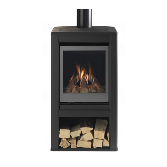
Inspire Gas Stove
Model's;
L and M
Fitted with 401FS or 401RC LUMINAIRE
Inset live fuel effect gas fire with LED fuel bed.
We trust that this guide gives sufficient details to enable this appliance to be installed,
operated and maintained satisfactorily. However, if further information is required, our
Valor Technical Helpline will be pleased to help.
Telephone 0844 879 35 88 (National call rates apply in the United Kingdom).
In the Republic of Ireland Telephone 01 842 8222.
©
GDC Group Ltd. SEPT 2018
Advertisement
Chapters
Table of Contents

Related Manuals for Valor Inspire L


Summary of Contents for Valor Inspire L
- Page 1 We trust that this guide gives sufficient details to enable this appliance to be installed, operated and maintained satisfactorily. However, if further information is required, our Valor Technical Helpline will be pleased to help. Telephone 0844 879 35 88 (National call rates apply in the United Kingdom).
- Page 2 THIS APPLIANCE IS FOR USE WITH NATURAL GAS (G20). THIS APPLIANCE IS SUITABLE ONLY FOR INSTALLATION IN THE UNITED KINGDOM (GB) AND THE REPUBLIC OF IRELAND (IE). © GDC Group Ltd. All rights reserved. No part of this publication may be reproduced in any material form (including photocopying), stored in any medium by electronic means (including in any retrieval system or database) or transmitted, in any form or by any means, whether electronic, mechanical, recording or otherwise, without the prior written permission of...
- Page 3 BS EN ISO 9001 quality system accepted by the British Standards Institute. The Highest Standards Valor is a member of the Benchark scheme and HHIC (Heating and Hot water Industry Council) that work to ensure high standards of safety, quality and performance.
-
Page 4: Installer Guide
INSTALLER GUIDE INSTALLER GUIDE FOR OWNER GUIDE SEE PAGES 39 TO 59 © Page 4 GDC Group Ltd. SEPT 2018... -
Page 5: Table Of Contents
INSTALLER GUIDE CONTENTS Section Page INSTALLER GUIDE 4 - 38 OWNER GUIDE 39 - 59 1. APPLIANCE & CLEARANCE DIMENSIONS 2. SAFETY (GAS & ELECTRICAL) 9 - 10 3. THE BENCHMARKING SCHEME 4. APPLIANCE DATA, EFFICIENCY AND NOx 4.1 General information. 4.2 Efficiency. - Page 6 INSTALLER GUIDE CONTENTS (Continued) Section Page 10. LED CHECK 10.1 Fitting the transformers male DC jack connector into convection box 10.2 Connecting the male and female DC jack into the LED circuit 10.3 Checking the LED operation 11. FITTING THE WALL LINERS 11.1 Fitting the rear wall liner 11.2 Fitting the Glass liners spacer support.
- Page 7 INSTALLER GUIDE CONTENTS (Continued) Section Page 15. FINAL REVIEW 33 - 34 16. SERVICING & PARTS REPLACEMENT 16.1 To remove the visual baffle. 16.2 To remove the window door panel. 16.3 To remove the fuel effect 16.4 To remove the top tray. 16.5 To remove the burner assembly 16.6 To access and remove the Inspection panel 16.7 To remove the wall liners...
-
Page 8: Appliance & Clearance Dimensions
INSTALLER GUIDE 1.APPLIANCE DIMENSIONS FIG 1 Product Dimension 1035 mm 863 mm 525 mm 525 mm 397 mm 397 mm 988 mm 816 mm 127 mm 127 mm FIG 2 L & M L & M Clearance Dimensions A (Sides) B (Shelf) Minimum to Combustible Material 100 mm... -
Page 9: Safety (Gas & Electrical)
INSTALLER GUIDE 2.SAFETY Installer Before continuing any further with the installation of this appliance please read the following guide to manual handling. The lifting weight of this appliance (kg) is approx as below: Model Weight Inspire Stove Model L inc 401 engine* 40 Kg Inspire Stove Model M inc 401 engine*... - Page 10 INSTALLER GUIDE ELECTRICAL SAFETY Before switching on, please read the operating instructions fully. - This appliance is not intended for use by persons (including children) with reduced physical, sensory or mental capabilities, or lack of experience and knowledge, unless they have been given supervision or instruction concerning use of the appliance by a person responsible for their safety.
-
Page 11: The Benchmarking Scheme
INSTALLER GUIDE 3.THE BENCHMARK SCHEME GDC Group is a licensed member of the Benchmark Scheme which aims to improve the standards of installation and commissioning of domestic heating and hot water systems in the UK and to encourage regular servicing to optimise safety, efficiency and performance. - Page 12 INSTALLER GUIDE Model 401FS in L or M Inspire Stove 401RC in L or M Stove Natural (G20) Natural (G20) Input - Max (Gross) 5.3 kW (18,084 Btu / hr) 5.3 kW (18,084 Btu / hr) FS Input - Med (Gross) 2.0 kW (6,824 Btu / hr) Input - Min (Gross) 1.6 kW (5,459 Btu / hr)
-
Page 13: Appliance Data, Efficiency And Nox
INSTALLER GUIDE Accessories 4. APPLIANCE DATA, EFFICIENCY,NOX AND 4.1 General information. The appliance information label is located on the burner engine on the base of the fire. This can be found by removing the Visual Baffle. 4.2 Efficiency. The efficiency of this appliance has been measured as specified in EN BS 613 and the results are as below : Models Efficiency % (Gross) -
Page 14: General Installation Requirements
INSTALLER GUIDE 5. GENERAL INSTALLATION REQUIREMENTS 5.1 Regulations, Standards and Law. The installation must be in accordance with these instructions. For the user’s protection, in the United Kingdom it is the law that all gas appliances are installed by competent persons in accordance with the current edition of the Gas Safety (Installation and Use) Regulations. -
Page 15: Flue / Chimney
INSTALLER GUIDE 5.4 Flue / Chimney. Before you install the stove make sure the chimney flue outlet is correctly positioned to align with the flue outlet on the stove and that the chimney is in good condition. If not, a chimney liner must be installed or a suitable class 2 gas flue used. The stove is approved for connection to a 102mm (4”) twin wall flue complying to BS715. -
Page 16: Fireguard Requirements
INSTALLER GUIDE 5.8 Fireguard requirements. A fireguard complying with BS 8423 should be fitted for the protection of young children, the elderly, the infirm and pet animals. 5.9 An extractor fan may only be used in the same room as this appliance, or in any area from which ventilation for the appliance is taken, if it does not affect the safe performance of the appliance. - Page 17 INSTALLER GUIDE © Page 17 GDC Group Ltd. SEPT 2018...
-
Page 18: Pack Contents
INSTALLER GUIDE PACK CONTENTS The items required for this appliance are packed in sections. NOTE: The Log fuel set and Vermiculite or Glass liner options are all fragile, so care necessary when handling please. Section 1 - Stove Fire unit contains: Stove inc Burner, convection box unit and Floor fixing bracket. -
Page 19: Gas Supply Connection
INSTALLER GUIDE 8.GAS SUPPLY CONNECTION The stove is designed for a rear connection only. A nut and olive are provided for an 8mm pipe inlet connection to the ‘T’ connector at the bottom front of the appliance. The ‘T’ connector can be rotated to allow connection and includes a valve for isolating the gas supply and a pressure test point. -
Page 20: Ignition Check
INSTALLER GUIDE 10. IGNITION CHECK Before attempting to install, it is worth checking that the ignition system performs satisfactorily. Slider Control (FS) Model NOTE: 2 handle finish options have been supplied Chrome and Black please ask the customers preference before selecting one to be fitted. 10.1 Fitting slider handle to control cam. -
Page 21: Fitting The Battery Into Spark Ignition Generator (Fs)
INSTALLER GUIDE 10.2 Fitting the battery into the spark ignition generator. At the front of the electronic spark generator there is a removable circular battery cover. Unscrew the cover in an anticlockwise direction. Remove any protective film from the battery if applicable and place into the generator. -
Page 22: Fitting Batteries Into Remote Control Handset (Rc)
INSTALLER GUIDE Remote Control (RC) Model 10.4 Fitting batteries into the remote control handset. The remote control handset is battery powered. There are two 1.5 Volt Alkaline ‘AA’ size batteries supplied. Remove the rear battery compartment cover from the remote control handset. Fit the batteries in to the handset. -
Page 23: Factory Reset Of Remote Handset (Rc)
INSTALLER GUIDE of the handset. Momentarily pressing and releasing the SET button advances through the settable features and pressing and releasing the MENU button returns to the previous one. Pressing + or – changes the displayed information, for example :- o H 24 –... -
Page 24: Led Check
INSTALLER GUIDE 11. LED CHECK Before attempting to install, it is worth checking that the LED system performs satisfactorily. 11.1 Fitting the transformer’s male DC jack connector into the convection box. At the front LHS and RHS of the convector box are access grommets fitted. -
Page 25: Fitting The Wall Liners
INSTALLER GUIDE FITTING THE WALL LINERS There are a range of wall liners available some may have a patterned/colouring or in the case of the glass a mirrored side depending on the liner set purchased. Ensure the decorated or glass mirrored side is fitted facing outwards. NOTE: All liners must be fitted into the convector box before the engine is refitted. -
Page 26: Burner And Supply Pipe Installation
INSTALLER GUIDE 14. BURNER AND SUPPLY PIPE INSTALLATION 14.1 Burner installation. 1. Ensure the transformer location is confirmed and the DC jack connector is fitted through the grommet into the convector box as as described in (Section 11) and connected to the burner unit. 2. -
Page 27: Lighting The Fire
INSTALLER GUIDE - 14.3.2 Adjusting flame height. When the burner is operating step the slider handle to the RHS, increments will be felt as the slider moves giving you the following outputs; Position 1 - After ignition Center burner is on LOW Position 2 - Moving slider handle one increment to RHS, Center burner is on HIGH. -
Page 28: Burner Checks - Rc Model
INSTALLER GUIDE 14.5 Burner checks - RC model 14.5.1 Lighting the fire. If closed open the isolating ‘T’ connector valve. Picking up and holding the handset firmly will unlock the keypad and the green light will illuminate a solid green. - Press and hold the ‘ON’... -
Page 29: Check Inlet Pressure
INSTALLER GUIDE 14.6 Check inlet pressure. The appliance is pre-set to give the correct heat input at the inlet pressure shown in section 4 of this guide. 1. Ensure that the fire is OFF then fit a pressure gauge at the test point. The test point is on the inlet ‘T’ connector. -
Page 30: Placement Of Clear Glass Pebbles
INSTALLER GUIDE 15.3.2 Open the bag of Clear Glass Pebbles (approx 700g) and carefully empty out the entire contents as in the below picture. The use of Gloves is recommended. The glass pebbles need to fully cover the glass panel evenly above the LEDS and flow out to the sides but not to the front or rear of the Top tray. -
Page 31: Placement Of The 3 Large Logs
INSTALLER GUIDE 15.3.4 Fit the three large logs as shown in the below picture. The logs are marked on there underside with 1, 2 or 3 dimples to identify them running left to right as in the below picture. NOTE: Ensure when laying these three logs in place, that no pebbles, chips or flakes interfer with how they sit onto the burner tubes. -
Page 32: Full Operating Checks
INSTALLER GUIDE 16. FULL OPERATING CHECKS 16.1 Check the burner operation. Repeat the checks conducted in section 10 &11. Please note: When first turned on from cold, the flames will appear predominantly blue. When operating the fire for the first time, some vapours may be given off which could set off smoke alarms in the vicinity. -
Page 33: Final Review
INSTALLER GUIDE This monitoring system must not be adjusted, bypassed or put out of operation. This monitoring system or any of its parts must only be exchanged using Valor authorised parts. FINAL REVIEW 1. COMPLETE THE INFORMATION IN THE GAS FIRE COMMISIONING CHECKLIST AND SERVICE RECORD OF THE OWNER GUIDE (See last pages of the OWNER guide). -
Page 34: Servicing & Parts Replacement
INSTALLER GUIDE 12. Advise that the appliance may give off a slight odour while new. This is quite normal and it will disappear after a short period of use. 13. Inform the customer that the Serial number for the appliance is located on the information label, located to the base of the burner and also stuck into this manual 14. -
Page 35: To Remove The Visual Baffle
INSTALLER GUIDE 19.1 To remove the visual baffle. 1. Remove the visual baffle held in place by two magnets, hold securely and carefully slide out the decorative trim and place carefully to one side. 3. Replace in the reverse order. 19.2 To remove the window door panel. -
Page 36: To Access And Remove The Inspection Panel
INSTALLER GUIDE 19.6 To access & remove the Inspection panel. 1. Complete sections 19.1 - 19.5 2. Unscrew the 4 screws, then remove and place the screws and panel to one side carefully. 3. Any inspection or cleaning of debris necessary can now be carried out. -
Page 37: To Remove The Gas Valve Led On/Off Switch Or Ignition Unit
INSTALLER GUIDE 8. Detach the electrode lead from the underside of the electrode tab. 9. Detach the thermocouple by unscrewing the thermocouple nut at the gas valve. 10. Remove the two screws from the pilot bracket. 11. Remove the pilot bracket and pilot assembly. 12. -
Page 38: To Replace The Burner Injectors (S)
INSTALLER GUIDE 6. The Manifold is connected to the three injectors and to the gas valve loosen and remove these four nuts/pipe connections and two fixing screws to release. 7.The On/Off switch has two wire connections both should be carefully pull out straightly and disconnected allowing the switch to be removed. -
Page 39: Owner Guide
OWNER GUIDE OWNER GUIDE FOR WARRANTY, SERVICE AND BENCHMARK INFORMATION SEE PAGES 55 TO 59 © Page 39 GDC Group Ltd. SEPT 2018... - Page 40 OWNER GUIDE LIST OF CONTENTS Section Page SAFETY (GAS & ELECTRICAL) 42 - 43 Appliance Minimum Clearances GAS & ELECTRIC CONSUMPTION OPERATING YOUR FIRE 44 - 52 The Oxysafe flame sensing and flue blockage safety system. 1. Operating the fire with SLIDER control (FS) model. 44 - 45 1a - Lighting the fire.
- Page 41 OWNER GUIDE LIST OF CONTENTS Section Page 4. LED fuel effect operation. CLEANING YOUR FIRE 52 - 53 Metal and painted parts. Removing and cleaning the window assembly. Cleaning anti-reflective “Clear Vision” coated glass Ceramic fuel effect log pieces and convector box compartment walls. Burner.
-
Page 42: Safety (Gas & Electrical)
OWNER GUIDE SAFETY IF YOU SMELL GAS DON’T SMOKE. EXTINGUISH ALL NAKED FLAMES. DON’T TURN ELECTRICAL SWITCHES ON OR OFF. TURN OFF THE GAS SUPPLY AT THE METER OR TANK AS APPROPRIATE. OPEN DOORS AND WINDOWS TO GET RID OF THE GAS. IMMEDIATELY CALL THE GAS EMERGENCY SERVICE FROM A NEIGHBOURS PHONE - GAS EMERGENCY CONTACT NUMBERS ARE;... -
Page 43: Appliance Minimum Clearances
OWNER GUIDE Do not hang clothing, towels or any other fabrics over the gas stove. Do not put more loose ceramic logs on the gas stove than the number given in the guide supplied with the ceramic fuel effect. This may have been attached to or placed inside this guide. -
Page 44: Gas & Electric Consumption
OWNER GUIDE GAS & ELECTRIC CONSUMPTION Natural Gas - Inspire Stove M or L fitted with 401FS engine Maximum (HIGH) NG input of 5.3 kw (Gross) Medium (MED) NG input of 2.0 kw (Gross) Minimum/Ignition (LOW) NG input of 1.6 kw (Gross) Natural Gas - Inspire Stove M or L fitted with 401RC engine Maximum (HIGH) -
Page 45: 1B - Adjusting The Flame Height
OWNER GUIDE 1b - Fireslide - adjusting flame height. When the burner is operating step the slider handle to the RHS, increments will be felt as the slider moves giving you the following outputs; Position 1 - After ignition Center burner is on LOW Position 2 - Moving slider handle one increment to RHS, Center burner is on HIGH. -
Page 46: 2B - To Turn On The Fire Manually
OWNER GUIDE The control required 3 AA size alkaline batteries to be inserted under the battery compartment cover. The orientation of these is shown moulded into the battery compartment and as shown below. After fitting the batteries and replacing the cover the fire can now operate. -
Page 47: 3B - Operating Instructions
OWNER GUIDE appears at the bottom left hand corner of the display, immediately release the power button. (A second flash of the unlock light and a longer beep will also sound at the time to release the power button). The Fire should be lit within a few seconds. N.B. -
Page 48: 3E - Setting The Day Of The Week
3e - Setting the day of the week Press and release the + and – buttons until the correct day of the week is shown on the display. (Mo = Monday, Tu= Tuesday, We=Wednesday, Th=Thursday, Fr=Friday, Sa=Saturday and Su=Sunday). Press “SET” to accept the day of the week and to progress to setting the Hour of the day. -
Page 49: 3H - 24 Hour Day Timer/Thermostat Mode And Snooze Mode
3h - 24-hours Day Timer/Thermostat mode and snooze mode. Snooze mode can be selected to work with in conjunction with either manual or thermostatic modes. You can switch between modes at any time with the handset unlocked by pressing and releasing mode button to toggle between modes. Note: If at any time the power button is pressed during operation, this will stop the fire and exit any automatic mode and return the handset to manual (MAN) operation mode. -
Page 50: 3K - Setting The "24 Hour Day Timer/Thermostat" Mode
If a different set temperature is required, while the display is showing this set temperature, press the + and – buttons to alter the setting. When finished either press set or leave and after a few seconds the new setting will be accepted and the display will return to the time of day screen. -
Page 51: 3L - Paging Feature Built Into Remote Handset To Find Its Location
next symbol show a flashing sun symbol- press and release SET- as Mo is flashing press and release SET again, enter the next time of 09:00- press and release SET- change the flashing sun symbol to a flashing moon symbol by pressing and releasing the + and –... -
Page 52: Led Fuel Effect Operation
4. LED fuel effect operation. Ensure the transformer is plugged into a suitable mains supply and the wall socket is switched ON. Switch ON the LED fuel effect simply by flicking the rocker switch as shown resulting in the red marking showing. The 8 LEDs will come ON and begin gently pulsing. -
Page 53: Cleaning Anti-Reflective "Clear Vision" Coated Glass
Hold the window panel base and lift upward until clear. 3. To remove the window door panel easier remove the visual baffle first. Cleaning anti-reflective “Clear Vision” coated glass Fingerprints are more visible on anti-reflective coated glass: it is advised to wear (rubber) gloves when handling the panel. -
Page 54: Maintenance
MAINTENANCE Battery replacement. Note: In order to ensure maximum battery life and optimal performance, we recommend that only 'Long Life' alkaline type replacement batteries are used - Low powered batteries in the valve or handset can generate false Error codes. Error codes (RC models) these could be generated on the handset (i.e. -
Page 55: Warranty, Service And Benchmark
WARRANTY, SERVICE AND BENCHMARK Standard Warranty Terms & Conditions The warranty is for 12 months subject to contract. In the United Kingdom servicing can be carried out either by a GDC service operative or a GAS SAFE REGISTER operative. You must register your fire by calling our telephone registration line on 08444 810 214. - Page 56 After servicing, complete the relevant “Service Interval Record” section of the Benchmark Checklist located on the inside back pages of this document. Our promise to you If you experience a fault with your new gas stove, we aim to provide a safe and high quality repair service supported by our dedicated national network of highly skilled operatives.
- Page 57 GAS FIRE COMMISSIONING CHECKLIST compliance with the appropriate Building Regulations and then handed to the customer to keep for future reference. www.centralheating.co.uk © Page 57 GDC Group Ltd. SEPT 2018...
- Page 58 SERVICE RECORD Service Provider SERVICE 01 SERVICE 02 SERVICE 03 SERVICE 04 SERVICE 05 SERVICE 06 SERVICE 07 SERVICE 08 SERVICE 09 SERVICE 10 www.centralheating.co.uk © Page 58 GDC Group Ltd. SEPT 2018...
-
Page 59: Serial Number Label
A LABEL CONTAINING THE SERIAL NUMBER AND BARCODE MAY HAVE BEEN PLACED INSIDE THIS BOX. SERIAL NUMBER LABEL TO BE AFFIXED HERE Pic shows FS data label metal plate position. Note: The Data label located on the burner assembly also contains this matching Serial number and Barcode information. - Page 60 © Page 60 GDC Group Ltd. SEPT 2018...
- Page 61 © Page 61 GDC Group Ltd. SEPT 2018...