Toro Pro Sneak 365 Operator's Manual
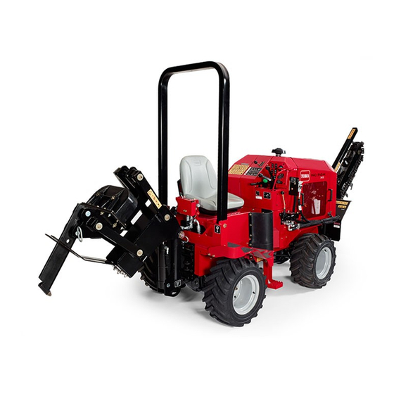
Vibratory plow
Hide thumbs
Also See for Pro Sneak 365:
- Installation instructions (4 pages) ,
- Operator's manual (48 pages) ,
- Operator's manual (16 pages)
Table of Contents
Advertisement
Quick Links
Advertisement
Table of Contents

Related Manuals for Toro Pro Sneak 365


Summary of Contents for Toro Pro Sneak 365
- Page 1 Form No. 3389-747 Rev A Pro Sneak 365 Vibratory Plow Model No. 25403—Serial No. 314000001 and Up Model No. 25403A—Serial No. 314000001 and Up Model No. 25403C—Serial No. 314000001 and Up *3389-747* A Register at www.Toro.com. Original Instructions (EN)
- Page 2 You are responsible for operating the product properly and safely. This manual uses 2 words to highlight information. You may contact Toro directly at www.Toro.com for product Important calls attention to special mechanical information and accessory information, help finding a dealer, or to register and Note emphasizes general information worthy of special your product.
-
Page 3: Table Of Contents
Contents Safety Improper use or maintenance by the operator or owner Safety ................3 can result in injury. To reduce the potential for injury, Safe Operating Practices........... 3 comply with these safety instructions and always Safety and Instructional Decals ......... 6 pay attention to the safety alert symbol , which Product Overview ............12... - Page 4 • Never carry passengers and keep pets and bystanders obstacles. away. • Use only Toro-approved attachments. Attachments can • Slow down and use caution when making turns and change the stability and the operating characteristics crossing roads and sidewalks. of the machine. Warranty may be voided if used with unapproved attachments.
- Page 5 Stop and inspect the equipment if you strike an object. Make any necessary repairs before restarting. Maintenance and Storage • Use only genuine Toro replacement parts to ensure that original standards are maintained. • Disengage the auxiliary hydraulics, lower the attachment, set the parking brake, stop the engine, and remove the •...
-
Page 6: Safety And Instructional Decals
Safety and Instructional Decals Safety decals and instructions are easily visible to the operator and are located near any area of potential danger. Replace any decal that is damaged or lost. Figure 3 1. Decal 117-2718 5. Decal 130-7360 9. Decal 125-6674 2. - Page 7 g0272 73 10 11 12 Figure 4 1. Decal 125-6684 6. Decal 117-3276 11. Decal 125-6135 (under the seat) 2. Decal 125-6694 7. Decal 125-4963 12. Decal 106-9290 (inside of machine) 3. Decal 125-8491 (behind the rubber 8. Decal 130-4291 13.
- Page 8 117-3276 1. Engine coolant under 3. Warning—do not touch the pressure hot surface. 2. Explosion hazard—read 4. Warning—read the the Operator's Manual. Operator's Manual. 125–6135 120-0627 1. Cutting/dismemberment hazard, fan—stay away from moving parts, keep all guards and shields in place. 125-6671 1.
- Page 9 125–6688 1. Explosion hazard—Read the Operator’s Manual; Do not use starting fluid. 125–6674 1. Disengage the parking 2. Engage the parking brake. brake. 125–6694 1. Tie down location 125–6680 4. Fast 1. Read the Operator’s Manual. 2. Turn left 5. Turn right 3.
- Page 10 125–8487 1. Crushing hazard, tire—read the Operator’s Manual; the extension step must be attached when the tires are in wide or doubled configuration. 127-1822 1. The engine cannot start 4. No vibration with the plow active. 2. High vibration 5. The engine can start with the plow inactive.
- Page 11 130-4291 1. Regeneration inhibit—read the Operator's Manual. 130-4343 1. Warning—read the 5. Warning—keep Operator's Manual. bystanders away. 2. Warning—do not operate 6. Warning—keep away the machine unless you from moving parts; keep have received instruction. all guards and shields in place.
-
Page 12: Product Overview
Controls Product Overview Become familiar with all of the controls before you start the engine and operate the machine. Throttle The throttle controls the engine speed. Push the knob to increase the engine speed. Pull the knob to decrease the engine speed. - Page 13 Creep-Control Lever The creep control lever controls the direction and speed of the machine while the attachments are in use. To go forward, push the lever forward. To reverse, pull the lever backward. The further you push or pull the lever, the faster the machine will travel.
-
Page 14: Specifications
Contact your Authorized Service Dealer or Distributor or go to www.Toro.com for a list of all approved Air-Filter Light attachments and accessories. This light illuminates if the air filter is in need of service. If Important: Use only Toro approved attachments. -
Page 15: Operation
Filling the Fuel Tank Operation DANGER Note: Determine the left and right sides of the machine from the normal operating position. Refer to Product In certain conditions, fuel is extremely flammable Overview (page 12). and highly explosive. A fire or explosion from fuel Important: Before operating, check the fuel and oil can burn you and others and can damage property. -
Page 16: Starting And Stopping The Engine
Note: If the outdoor temperature is below freezing, 1. Park the machine on a level surface, lower any attachments, stop the engine, and remove the key. store the machine in a garage to keep it warmer and aid in starting. 2. - Page 17 Note: Do not start the plow vibration until the blade tip has entered the ground. 6. Move the vibratory-plow lever to start the plow vibration. 7. Slowly lower the plow blade into the ground as the machine moves forward. 8. Use the creep control lever to control the direction and speed of the machine during plowing.
-
Page 18: Rotating The Wheels
Rotating the Wheels The wheels can be installed to provide a narrow or a wide overall width of machine. Install the wheels with the deep concave toward the machine for operation in tight areas or the shallow concave toward the machine for wider stability. Important: Only operate on level ground with the narrow wheel configuration. -
Page 19: Transporting The Machine
Transporting the Machine Loading the Machine Important: Ensure that the trailer and ramp can support both your weight plus the weight of the machine with any attachments. 1. Start the engine. 2. Move the attachments to transport position. 3. Secure the trailer hitch to your vehicle and put a block at the front and rear of the trailer wheels. -
Page 20: Maintenance
Important: Refer to your engine Operator's Manual for Note: Download a free copy of the Electrical Schematic or additional maintenance procedures. Hydraulic Schematic for your machine by visiting www.Toro.com and searching for your machine from the Manuals link on the home page. -
Page 21: Premaintenance Procedures
Maintenance Service Maintenance Procedure Interval • Change the transmission oil. • Change the engine coolant (See an Authorized Service Dealer). • Check the alternator drive belt tension. Every 1,000 hours • Replace the hydraulic filter. • Change the hydraulic fluid. •... -
Page 22: Engine Maintenance
Engine Maintenance Servicing the Air Cleaner Service Interval: Before each use or daily—Check the air filter service indicator light (more frequently if conditions are dusty or sandy). Every 250 hours—Remove the air cleaner cover, clean out any debris, and check the air filter service indicator light (more frequently if conditions are dusty or sandy). -
Page 23: Servicing The Engine Oil
Replacing the Filters SAE 20W If the air filter light illuminates, perform the following steps. SAE 15W -40 1. Gently slide the primary filter out of the air cleaner body (Figure 21). SAE 10W -30 Note: Avoid knocking the filter into the side of the SAE 5W -30 body. -
Page 24: Servicing The Diesel Particulate Filter (Dpf)
Changing the Oil Filter Note: When using different oil, drain all old oil from the crankcase before adding new oil. 1. Drain the oil from the engine; refer to Changing the Engine Oil (page 24). 5. Install the oil fill cap and dipstick. 2. -
Page 25: Fuel System Maintenance
Fuel System removed and replaced with a clean DPF. If the DPF is not cleaned at the 50 g/L level, the engine will continue to run Maintenance at the de-rated 85% power level until the ash accumulation reaches 60 g/L. When the ash level reaches 60 g/L, the engine will de-rate to 50% power. -
Page 26: Replacing The Fuel Filter Canister
Replacing the Fuel Filter Electrical System Canister Maintenance Service Interval: Every 500 hours—Replace the fuel filter/water separator. Servicing the Battery 1. Clean the filter head and the outside of the fuel filter. Service Interval: Every 100 hours—Check the battery 2. Turn the filter counterclockwise and remove the filter electrolyte level (replacement battery from the filter head. -
Page 27: Drive System Maintenance
Drive System Maintenance Servicing the Tires Checking the Tires and Lug Nuts Service Interval: Before each use or daily—Check the tire pressure. Before each use or daily—Check the lug nuts. G025670 Figure 26 • Do not exceed the rated tire pressure. To ensure long tire life and safe handling, check tire pressure daily, refer to 1. -
Page 28: Servicing The Transmission And Axles
Front axle oil capacity: approximately 2.4 L (2.5 US qt) Rear axle oil capacity: approximately 2.4 L (2.5 US qt) Toro Premium Gear Oil is available from an Authorized Toro Service Dealer. See the parts catalog for part numbers. Checking the Transmission Oil... -
Page 29: Cooling System Maintenance
Cooling System Note: The oil level should be even with the bottom of the fill plug hole. Maintenance 4. Add oil to raise the oil level up to the bottom of the fill plug hole. 5. Install the fill plug. Servicing the Cooling System 6. -
Page 30: Belt Maintenance
Checking the Engine Coolant Level Belt Maintenance Check level of coolant at the beginning of each day. Capacity of the system is 8.5 L (9 qt). Checking the Alternator Drive 1. Carefully remove the radiator cap. Belt Tension CAUTION Service Interval: Every 1,000 hours If the engine has been running, the 1. -
Page 31: Controls System Maintenance
Controls System 4. Run the engine for 5 minutes and check the tension; the tension should be between 7 to 10 mm (1/4 to 3/8 Maintenance inch) under load of 98 N-m (22 ft-lb). The factory adjusts the controls before shipping the machine However, after many hours of use, you may need to adjust the controls. -
Page 32: Cleaning The Directional Controls Linkage Assembly
5-gallon pails or 55-gallon drums. See Parts Catalog or an Authorized Service Dealer for part numbers.) Figure 34 Alternate fluids: If the Toro fluid is not available, other fluids 1. Adjustment nut may be used provided they meet all the following material properties and industry specifications. - Page 33 CAUTION During regeneration, the diesel particulate filter becomes extremely hot and can cause serious burns. Keep your body and hands away from the engine during regeneration. 5. Remove the cap from the filler neck and check the fluid level on the dipstick (Figure 37). The fluid level should be between the marks on the g018923 dipstick.
- Page 34 Figure 40 1. Hose clamp Figure 38 7. Disconnect the electrical lead to the oil temperature 1. Upper left panel 2. Hydraulic tank sending unit at the bottom of the reservoir. 8. Loosen the hydraulic tank straps and remove the 3.
- Page 35 13. Install the hose to the tank and secure the clamps. 14. Install the hydraulic tank assembly. 15. Fill the hydraulic tank with approximately 25.8 L (6.8 US gallons) of Toro premium all season hydraulic fluid ISO VG 46. Dispose of the used oil at a certified recycling center.
-
Page 36: Rops Maintenance
Before you operate the machine, always ensure that the ROPS the ROPS and ROPS parts. If you have any doubts and the seat belt are properly installed and in good working about the ROPS system, contact an Authorized Toro order. Service Dealer. -
Page 37: Cleaning
Cleaning Storage 1. Lower any attachments, stop the engine, and remove Removing Debris from the the key. Machine 2. Remove dirt and grime from the entire machine. Important: You can wash the machine with mild Service Interval: Before each use or daily detergent and water. -
Page 38: Troubleshooting
Troubleshooting Problem Possible Cause Corrective Action The starter does not crank. 1. The controls are not in the neutral 1. Move all of the controls to the Neutral position. position. 2. The electrical connections are 2. Check the electrical connections for corroded or loose. - Page 39 Problem Possible Cause Corrective Action The engine starts, but does not keep 1. The fuel tank vent is restricted. 1. Loosen the cap. If the engine runs with running. the cap loosened, replace the cap. 2. There is dirt or water is in the fuel 2.
- Page 40 Problem Possible Cause Corrective Action The engine overheats. 1. More coolant is needed. 1. Check and add coolant. 2. There is restricted air flow to the 2. Inspect and clean the side panel radiator. screens with every use. 3. The crankcase oil level is incorrect. 3.
- Page 41 Problem Possible Cause Corrective Action The engine loses power. 1. The engine load is excessive. 1. Reduce the load; use lower ground speed. 2. The crankcase oil level is incorrect. 2. Fill or drain to the full mark. 3. The air cleaner filters are dirty. 3.
- Page 42 Notes:...
- Page 43 Notes:...
- Page 44 Toro importer. If all other remedies fail, you may contact us at Toro Warranty Company. Australian Consumer Law: Australian customers will find details relating to the Australian Consumer Law either inside the box or at your local Toro Dealer.