
Related Manuals for Extron electronics IN1806 Series


Summary of Contents for Extron electronics IN1806 Series
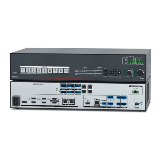
- Page 1 User Guide Scalers IN1806 and IN1808 Series Scaling Presentation Switchers 68-3131-01 Rev. A 05 19...
-
Page 2: Safety Instructions
Safety Instructions Safety Instructions • English Istruzioni di sicurezza • Italiano AVVERTENZA: Il simbolo, , se usato sul prodotto, serve ad This symbol, , when used on the product, is intended to WARNING avvertire l’utente della presenza di tensione non isolata pericolosa alert the user of the presence of uninsulated dangerous voltage within the all’interno del contenitore del prodotto che può... - Page 3 Copyright www.extron.com © 2019 Extron Electronics. All rights reserved. Trademarks All trademarks mentioned in this guide are the properties of their respective owners. The following registered trademarks ( ® ), registered service marks ( ), and trademarks ( ) are the property of RGB Systems, Inc. or Extron Electronics (see the current list of trademarks on the...
- Page 4 FCC Class A Notice This equipment has been tested and found to comply with the limits for a Class A digital device, pursuant to part 15 of the FCC rules. The Class A limits provide reasonable protection against harmful interference when the equipment is operated in a commercial environment.
-
Page 5: Conventions Used In This Guide
Conventions Used in this Guide Notifications The following notifications are used in this guide: CAUTION: Risk of minor personal injury. ATTENTION : Risque de blessure mineure. ATTENTION: • Risk of property damage. Risque de dommages matériels. • NOTE: A note draws attention to important information. TIP: A tip provides a suggestion to make working with the application easier. -
Page 7: Table Of Contents
Contents Advanced Submenu ........40 Introduction ........... 1 Communication Submenu ......43 About this Guide ..........1 Front Panel Lockout (Executive Modes) .... 44 Product Description ..........1 Input Presets ............ 45 Models ............2 Power Save Modes .......... 45 Integrated Digital Twisted Pair Extension .. - Page 8 Internal Web Page ..........102 Accessing the Web Page ........ 102 Disabling Compatibility Mode ...... 103 Web Page Components ......... 103 Device Info Panel ........104 Inputs Panel..........104 Roles and Permissions Panel ...... 105 Device Status Panel ........107 Outputs Panel ..........
-
Page 9: Introduction
Introduction This section provides general information about this guide and the Extron IN1806 and IN1808 Series. Topics in this section include: About this Guide • • Product Description Features • • Control Methods • Application Diagrams Licensed Third-Party Software Used in the Scalers •... -
Page 10: Models
Models The presentation switchers are available in the following models: Model Description Inputs Outputs IN1806 1U high 1 DisplayPort 1 HDMI 5 HDMI 1 DTP2/XTP/HDBT 1 HDMI Loop Out IN1808 1U high 1 DisplayPort 1 HDMI 5 HDMI 1 DTP2/XTP/HDBT 2 DTP2/XTP 1 HDMI Loop Out IN1808 IPCP SA... -
Page 11: Audio Integration Capabilities And Available Power Amplifiers
RS-232 and IR signal insertion The DTP2 inputs and output are configured for unidirectional RS-232 Ethernet insertion as the twisted pair control connection. Ethernet insertion allows you to employ Ethernet drivers from either the local controller or an external controller connected on the IP network. IR output signals can be inserted from a control system and transmitted over the single shielded CATx cable together with the video and audio, enabling control of a source or display. - Page 12 • Integrated DTP2 extension supports transmission of 4K/60 video, audio, and control up to 330 feet (100 meters) over a shielded CATx cable. • HDCP 2.2 compliant — Ensures display of content-protected 4K video media and maintains interoperability with earlier versions of HDCP. •...
- Page 13 User-selectable HDCP authorization for DTP2 and HDMI inputs — Allows inputs • 2 through 6 or 2 through 8 to appear HDCP compliant or non-HDCP compliant to the connected source, which is beneficial if the source automatically encrypts all content when connected to an HDCP-compliant device.
- Page 14 Image freeze control — A live image can be frozen using RS-232, USB, or Ethernet • control. • On-screen menus — Intuitive on-screen menus allow for easy system setup using the front panel controls. Key parameters such as input and output video formats are conveniently grouped on the initial screen, while additional screens Quick Setup...
- Page 15 Audio switching transitions — The audio output level automatically ramps down and • then ramps up to match the video during switching transitions. • Integrated audio delay — The audio output is automatically delayed to compensate for latency introduced by the video processing. •...
-
Page 16: Additional Features Of The In1808 Series Ipcp Models
Additional Features of the IN1808 Series IPCP Models Integrated IPCP Pro control processor — A built-in IPCP Pro 3355M control • processor enables complete AV system control. • Energy efficient Class D stereo or mono amplifier: 2 x 50 watts @ 4 ohms, 2 x 25 watts @ 8 ohms, or 1 x 100 watts @ 70 volts —... -
Page 17: Control Methods
Multi-level password protection — Allows security to be set based on user roles. • • Create controller groups — Allows multiple IP Link Pro control processors to be grouped together to function as one when configured with Global Configurator Professional. Control Methods Control the IN1806 and IN1808 Series scalers using one or more of the following methods: •... - Page 18 Extron SF 3CT LP Ceiling Speakers Extron Audio XPA 2001-70V 100-240V 0.5A, 50-60Hz XPA 2001-70V ATTENUATION INPUTS REMOTE 70 V OUTPUT 50mA Mono Ampli er (SUMMED) LIMITER/PROTECT 80 Hz SIGNAL ∞ CLASS 2 WIRING Audio Boundary Microphones Audio HDMI Audio Ethernet Extron 100-240V~0.7A MAX...
-
Page 19: Licensed Third-Party Software Used In The Scalers
Licensed Third-Party Software Used in the Scalers The scalers use various licensed third-party software packages during operation. To view details about third-party packages and associated licensing, see the following: • PCS — To view a copy of a listed package license, select PCS from the About menu. -
Page 20: Installation
Installation This section contains information on how to connect cables to the IN1806 and IN1808 Series models. Topics in this section include: • Installation Overview • Rear Panel Connections Connection Details • Installation Overview Turn off or disconnect all related equipment. Ensure that video sources and output displays are all turned off and disconnected from the power source. - Page 21 100-240V ~ 1.5A MAX INPUTS (DTP2/XTP) INPUTS OUTPUTS AUDIO INPUTS AUDIO INPUTS OUTPUTS OUTPUTS REMOTE REMOTE OUTPUTS (DTP2/XTP/HDBT) DTP2/XTP II DTP2/XTP/HDBT +48V +48V LINK LINK LINK LINK LINK LINK OVER TP OVER TP MIC/LINE MIC/LINE RS-232 RS-232 RESET RESET +48V +48V 100-240V 50/60 Hz Tx Rx...
- Page 22 AC power connector — Connect a standard IEC power cord (provided) from a 100 to 240 VAC, 50-60 Hz power source to this connector (see figure 3 on page 12 figures 4 through 6 on the previous page). DisplayPort input connector (input 1) — Connect a DisplayPort source to this female DP connector (see figure 3 figures 4 through...
- Page 23 DTP2/XTP/HDBT output connector (output 1B) — This connector and the HDMI output connector (1A) are mirrored, meaning that they display the same image (see figure 3 on page 12 and figures 4 through 6 on page 13). Connect a DTP or DTP2 receiver, an XTP matrix switcher, or an •...
- Page 24 Over TP IR pass-through connector — To transmit or receive infrared data to and from a sink connected to a DTP or DTP2 receiver, XTP matrix, or HDBaseT display, connect a control device to the 3-pole Over TP IR captive screw port (see figure 3 on page 12 and figures 4 through 6...
- Page 25 LAN connector (IN1806 and IN1808 base model only) — To control the IN1806 and the IN1808 base model through Ethernet, connect a LAN or WAN to this RJ-45 LAN connector (see figure 3 on page 12 and figures 4 through 6 on page 13).
- Page 26 IPCP control processor (IN1808 IPCP SA and IN1808 IPCP MA 70 only) — The IN1808 IPCP models include a built-in IPCP Pro 355M Control Processor (see figures 5 and 6 on page 13). For these models, the LAN connector is incorporated in the IPCP control processor.
-
Page 27: Connection Details
LAN port — Single Ethernet connector. The IN1806 and the IN1808 base model each have a LAN connector to the left of the Remote RS-232 connector (see figures 3 and , on pages 12 and 13) instead of the LAN and AV LAN ports on the IPCP models (see figures 5 and , on page 13). -
Page 28: Hdmi Connections
ATTENTION: • The length of the exposed wires in the stripping process is critical. The ideal length is 3/16 inch (5 mm). If the exposed portion is longer, the wires may touch, causing a short circuit between them. If the exposed wires are shorter, they can be easily pulled out, even if tightly fastened by the captive screws. - Page 29 The IN1806/IN1808 connectors require the LockIt brackets to be mounted as follows: • HDMI inputs 2, 4, and 6 — Side mounted. Can be stacked with the connectors below them. HDMI inputs 3 and 5, HDMI Loop Out — Stack mounted. Because these connectors •...
-
Page 30: Twisted Pair Recommendations For Dtp, Xtp, And Hdbt Communication
Twisted Pair Recommendations for DTP, XTP, and HDBT Communication Use the following pin configurations for shielded twisted pair cables used for DTP or HDBaseT communication. TIA/EIA T568B Pins: 12345678 Wire Color White-orange Orange White-green Blue White-blue Green Insert Twisted Pair Wires White-brown RJ-45 Brown... -
Page 31: Operation
Operation This section contains information on the front panel operation, on-screen display menu system, and reset modes of the scalers. Topics in this section include: Front Panel Overview • • Powering Up • Selecting an Input Selecting a Logo • •... - Page 32 Front panel configuration port — Connect a host device to the USB mini-B port for device configuration, control, and firmware upgrades. Input selection buttons — (1 through 6 on IN1806, 1 through 8 on IN1808 Series) Press one of these buttons to select an input. The buttons light amber for audio and video, green for video only, or red for audio only.
-
Page 33: Powering Up
Powering Up To power on the unit, connect the provided IEC power cable between the rear panel power connector and an AC power source. During power-up, the following occurs in the order listed: All backlit buttons (the input buttons and the button) blink amber, red, and green Logo for approximately 15 seconds. -
Page 34: Using The On-Screen Menu System
Using the On-Screen Menu System The on-screen (OSD) menus are used primarily for the initial setup of the device. The on-screen menu presents configuration options on a local monitor, and settings can be adjusted with front panel controls. NOTES: The on-screen menu has a default timeout of 60 seconds. •... -
Page 35: Menu Overview
Menu Overview In the on-screen menu, the product name is displayed at the top of the right column. The active input and output resolutions are displayed in the bottom border. The on-screen menu contains eight submenus with various submenu items of adjustable settings or device information (see the Submenus table, below). -
Page 36: Using The Menu Screens
Using the Menu Screens Figure 16. On-screen Menu Example To open the on-screen menu: Connect a display device to an HDMI output connector (see Rear Panel Connections, beginning on page 12). Press the button to open the on-screen menu. Menu Enter To navigate the on-screen menu: >... -
Page 37: Device Info Screen
To exit the on-screen menu system: From any menu screen, press the button to close the on-screen menu and exit the Menu system. Alternatively, wait for the menu display to time out (approximately 60 seconds). Device Info Screen Figure 17. Device Info Screen The read-only screen is listed first in the submenus (left) panel. -
Page 38: Quick Setup Submenu
Quick Setup Submenu Figure 18. Quick Setup Submenu submenu is displayed by default when the OSD is first opened, and Quick Setup provides quick access to frequently-used settings. This submenu contains the following items, which also appear on other submenus in the system: INn: Input Mode —... -
Page 39: Picture Controls Submenu
Picture Controls Submenu Figure 19. Picture Controls Submenu Adjusting the picture controls When you select a submenu item, the menu collapses so that the Picture Controls item is displayed alone on the screen to facilitate adjustment (see figure 20). The separate item field contains blue arrows that indicate which front panel arrow buttons to press to adjust the item. - Page 40 Available picture controls submenu adjusts the following picture settings: Picture Controls NOTE: When the aspect ratio changes as a result of commands being Fill Follow entered, the values are updated accordingly. Image Position Image Size • Auto-Image — Press the button to execute an Auto-Image on the active input, Enter to restore it to the default size and position.
-
Page 41: Input Submenu
Input Submenu Figure 21. Input Submenu submenu adjusts the active input. Input • INn: Input Mode — Displays the signal type of the selected input. For input 1 it shows if a DisplayPort source is connected, • DisplayPort No Signal if not (view-only). - Page 42 • HDCP Authorized — This feature determines if a digital input reports as an HDCP authorized sink to a source. Select this item to enable or disable HDCP communication by selecting whether the IN1806 or IN1808 Series input reports to the source as an ...
- Page 43 Press . The display EDID is saved to the selected custom slot and assigned Enter to the connected inputs. Input EDID Resolutions Resolution 23.98 Hz 24 Hz 25 Hz 29.97 Hz 30 Hz 50 Hz 59.94 Hz 60 Hz 640x480 800x600 1024x768 1280x768...
-
Page 44: Output Submenu
Output Submenu Figure 23. Output Submenu submenu enables you to configure the output resolution, refresh rate, HDMI Output and TP format, TP mode, HDCP notification, and Loop Out format and connected input. • Output Rate — Select this item to specify the output resolution and refresh rate. The IN1806 and IN1808 Series scalers have a range of resolutions from which to choose (see the Output Resolutions and Refresh Rates... - Page 45 Output Resolutions and Refresh Rates Resolution 23.98 Hz 24 Hz 25 Hz 29.97 Hz 30 Hz 50 Hz 59.94 Hz 60 Hz 640x480 800x600 1024x768 1280x768 1280x800 1280x1024 1360x768 1366x768 1440x900 1400x1050 1600x900 1680x1050 1600x1200 1920x1200 480p 576p 720p 1080i 1080p 2048x1080 (2K) 2048x1200...
-
Page 46: Audio Submenu
TP 1B Format — Select from the list of submenu items, then • TP 1B Format Output press the buttons to select the format. The format choices are the same as for HDMI 1A: • Auto (based on the EDID of the sink) (default) •... - Page 47 Audio Mute — Select this item to mute and unmute the output audio. You can make • the following audio mute selections: Off — Audio output is not muted (default). • On — Mutes both the analog and the embedded digital audio outputs. •...
-
Page 48: Advanced Submenu
NOTE: DSP is provided to enable configuration of specific audio features, such as Mic/Line mixing, signal processing (ducking, feedback suppression, dynamics, equalization, and delay), gain adjustment, volume control, and phantom power. • Use PCS to configure DSP and other audio parameters for the audio inputs and outputs (see the IN1806 and IN1808 Series PCS Help File for detailed instructions). - Page 49 NOTES: • By default all test patterns include a single pixel wide crop pattern line. • The Audio Test pattern displays a crop pattern and also outputs pink noise at 48 kHz, 24 bit. • Test pattern selections persist through a power cycle. Screen Saver —...
- Page 50 : Auto Memory — Enables or disables Auto Memory. When Auto Memory is set • (default), the IN1806 or IN1808 stores the current input configuration and picture control values. The scaler stores 32 auto memories per input, with input configuration and picture control data for each video resolution.
-
Page 51: Communication Submenu
The switch effects, listed below in order of appearance on the menu, include: Seamless Fade (default) — Displays a final frozen frame of the previous input while • the newly selected input fades in (see figure 27, Fade thru Black — The current input fades to black before the newly selected •... -
Page 52: Front Panel Lockout (Executive Modes)
DHCP Mode — When this mode is enabled ( ), the unit obtains an IP address and • other network settings from the DHCP server. The default is To enable or disable DHCP mode: Select from the submenu and press DHCP Mode Communications Enter... -
Page 53: Input Presets
Input Presets The IN1806 and IN1808 Series scalers have 128 memory slots in which you can save input presets. These presets are global to all inputs that contain the settings for use with a matrix switcher. A matrix switcher with multiple types of video inputs (such as an XTP matrix switcher) can be placed upstream from the IN1806 and IN1808 Series to expand the number of video sources. -
Page 54: Reset Modes
Reset Modes The IN1806 and IN1808 Series scalers have three reset modes (numbered 1, RESET RESET 4, and 5). Use a small screwdriver or stylus to press and hold the recessed Reset button to advance through the modes. The green Reset LED blinks to indicate each mode that is enabled (see the Reset Mode Summary table). -
Page 55: Rs-232 And Ir Signal Insertion
RS-232 and IR Signal Insertion The twisted pair input and output ports allow you to insert RS-232 and IR control signals onto the same cable that carries video and audio to extend them to the Over TP port on a connected endpoint (see figure 30 on the next page and figure 31... -
Page 56: Ethernet To Rs-232 Insertion
Ethernet to RS-232 Insertion Figure 30 is an example of an Ethernet to RS-232 insertion, in which an Extron controller provides control of an HD camera via the IN1806 and IN1808 Series and a DTP HDMI 4K 230 transmitter. Configure this type of insertion as follows: Connect a TP cable from the control system to the scaler LAN port, directly or via a network. -
Page 57: Captive Screw Ir Signal Insertion
Changing the starting point By default the UART start point is 2000. You can change the starting port number by any of the following methods: • Using the Product Configuration Software (see IN1806 and IN1808 Series PCS Help file) • Using SIS commands (see the Set UART start point SIS command on page 80) - Page 58 To insert IR signals via the Over TP captive screw connector: Connect the COM (serial) port of the control system to the Over TP IR captive screw port (output port 1B in this example). Connect the TP cable from the IN1806 and IN1808 Series RJ-45 Out connector to the DTP input of the endpoint.
-
Page 59: Sis Configuration And Control
The copyright message is displayed upon connecting to a scaler via TCP/IP or Telnet or after a power cycle via RS-232, and depends on the scaler model. (c) Copyright YYYY, Extron Electronics, IN180n <model>, Vn.nn, 60-16nn-0n ] (day, date, and time as in... -
Page 60: Password Messages
Password Messages If the IN1806 or IN1808 is protected by a password, the following password message prompts you for the password to access the scaler features. Password The prompt requires a password, followed by a carriage return. The prompt is repeated if the correct password is not entered. -
Page 61: Error Responses
Error Responses When the scaler receives a valid command, it executes the command and sends a response to the host device. If the unit is unable to execute the command, it returns an error response to the host. E01 — Invalid input number E17 —... -
Page 62: Symbol Definitions
Symbol Definitions NOTES: • Upper- and lowercase text can be used interchangeably unless otherwise stated. • If the unit does not support or recognize an entered command, it ignores the command and nothing happens. • Space Carriage return with line feed Carriage return with no line feed Pipe (can be used interchangeably with the } character) Escape... - Page 63 Internal temperature In degrees Celsius. Response is two digits, padded with a zero. Horizontal and vertical nnn.nn Response is three digits with two decimal frequencies places, padded with zeros. (Example: 075.32) Text label Up to 32 characters. Cannot contain , (comma) ,*, or NOTES: •...
- Page 64 EDID emulation or output rate 0 = Automatic (default input EDID, matches the current output resolution) (See the Input EDID and Output 1 = Output 1A HDMI (available for EDID export only) Resolutions table. 2 = Output 1B TP (available for EDID export only) 3 = Loop output (available for EDID export only) 201 –...
- Page 65 Test patterns 0 = Off (default) 1 = Crop 2 = Alternating pixels 3 = Crosshatch 4 = Color Bars 5 = Grayscale 6 = Audio test — Crop pattern with orbiting text AUDIO TEST and outputting pink noise at LPCM-2Ch, 48 kHz, 24-bit.
- Page 66 Verbose mode 0 = None (default for LAN connection) 1 = Verbose mode (default for RS-232 and USB connection) 2 = Tagged responses to queries 3 = Verbose mode and tagged responses NOTES: • In verbose response mode, the IN1806 or IN1808 returns unsolicited responses for value and setting changes that may result from a signal change, or a setting adjustment made via...
- Page 67 Video switch effect 0 = Cut through black — The input instantly cuts to black, then cuts to the newly selected input with no fading. 1 = Fade through black — The input fades to black before the newly selected input fades in. 2 = Seamless fade (default) —...
- Page 68 Video signal status 0 = Video, TMDS, or DP signal not detected 1 = Video, TMDS, or DP signal detected X5& Remote port number 1 = Remote port (3-pole captive screw) 7 = Universal asynchronous receiver-transmitter (UART) on DTP Input 7 (IN1808 Series only) 8 = Universal asynchronous receiver-transmitter (UART) on DTP Input 8 (IN1808 Series only) 9 = UART on DTP/HDBT Output 1B...
- Page 69 Key effect 0 = Disabled (default) 1 = Transparency 2 = RGB key 3 = Level key 4 = Alpha key Audio playback file slot number 1 through 16 Highest priority for playback is slot 1, descending to lowest priority slot 16. Playback state 0 = Stop or stopped 1 = Play or playing...
-
Page 70: Command And Response Tables For Sis Commands
Command and Response Tables for SIS Commands Command ASCII Command Response Additional Description (Host to Scaler) (Scaler to Host) Input Configuration Input Selection Video and audio input •All Select video and audio from input output Video input •Vid Select video from input to output = 1 for all models. - Page 71 Command ASCII Command Response Additional Description (Host to Scaler) (Scaler to Host) Input Configuration (continued) Input EDID Specify an EDID value X2!] EDID Edid A Assign EDID to input X2!] View assigned EDID EDID View EDID for input X2!] Save the output EDID to a EDID EdidS Save the EDID of output...
- Page 72 Command ASCII Command Response Additional Description (Host to Scaler) (Scaler to Host) Input Configuration (continued) HDCP Authorized Enable HDCP support Enable HDCP encryption support for *1HDCP HdcpE input (default). HDCP Authorized is permanently enabled for DisplayPort IN1. NOTE: Disable HDCP support Disable HDCP encryption support for *0HDCP HdcpE...
-
Page 73: Picture Adjustments
Command ASCII Command Response Additional Description (Host to Scaler) (Scaler to Host) Input Configuration (continued) Auto-input Switch Mode Set the auto-input switch EX3) X3)] AUSW Ausw Set the auto-input switch mode to mode View auto-input switch X3)] View current auto-input switch mode AUSW mode Set user priority order... - Page 74 Command ASCII Command Response Additional Description (Host to Scaler) (Scaler to Host) Picture Adjustments (continued) Contrast Set a specific value X1%] Set the range of image light and dark CONT Cont values (contrast level) to for input Increment contrast value X1%] + CONT Cont...
- Page 75 Command ASCII Command Response Additional Description (Host to Scaler) (Scaler to Host) Picture Adjustments (continued) Vertical Position (Shift) — Image Specific value X1^] Set the vertical position of the image VCTR VctrI1* in relation to the top left corner of the output raster to Increment value X1^]...
- Page 76 Command ASCII Command Response Additional Description (Host to Scaler) (Scaler to Host) Output Configuration Output Video Mute Unmute output video Unmute video output Mute output video Mute video output Mute video and sync Mute video and sync on output View mute status X4@ ] View video mute status for output...
- Page 77 Command ASCII Command Response Additional Description (Host to Scaler) (Scaler to Host) Output Configuration (continued) HDMI Output Format Set output format X4*] Set the colorspace and format for HDMI VTPO Vtpo output View format setting X4*] View the current output colorspace and VTPO format for output View auto output format...
- Page 78 Command ASCII Command Response Additional Description (Host to Scaler) (Scaler to Host) Output Configuration (continued) Screen Saver (Enabled when there is no active video on selected input) Set mode X4)] Set the screen saver mode for the SSAV SsavM1* output to View mode X4)] M1 SSAV...
- Page 79 Command ASCII Command Response Additional Description (Host to Scaler) (Scaler to Host) Logos (continued) Clear Logo Clear logo slot X4#] PRST PrstX3* Clear logo slot and change its name to [unassigned]. Logo Name Write name X1$] Assign logo name to logo UNAM Unam L View logo name...
- Page 80 Command ASCII Command Response Additional Description (Host to Scaler) (Scaler to Host) Logos (continued) Logo Key Effect Disabled E X4# *0 LKEF Lkef Disable key effect for logo Transparency E X4# *1 LKEF Lkef Enable transparency for logo RGB Key E X4# *2 LKEF Lkef...
- Page 81 Command ASCII Command Response Additional Description (Host to Scaler) (Scaler to Host) Presets Input Presets Values Saved in Input Presets Preset Name H Image Position Film Mode Detection V Image Position Contrast H Image Size Brightness V Image Size Detail Recall preset X2^] 2Rpr...
- Page 82 Command ASCII Command Response Additional Description (Host to Scaler) (Scaler to Host) Audio Configuration Audio Input Format Set input audio format X5@] AFMT AfmtI Set the audio format for input View audio input format X5@] AFMT View audio input format for input NOTE: Audio input formats 4 and 5 detect and use embedded digital audio when present.
- Page 83 Command ASCII Command Response Additional Description (Host to Scaler) (Scaler to Host) Audio Configuration (continued) Audio Input Name X1$] Write name ANAM AnamI Set the name of audio input X1$] View name View the name of the audio input. ANAM Audio Output Name Write name X1$]...
- Page 84 Command ASCII Command Response Additional Description (Host to Scaler) (Scaler to Host) Audio Configuration (continued) Configure Playback (continued) Set delay X8$] Set the number of seconds the unit CPLY CplyD waits before repeating playback of the file in slot View delay X8$] CPLY View number of seconds delay (...
- Page 85 Command ASCII Command Response Additional Description (Host to Scaler) (Scaler to Host) Advanced Configuration Test Pattern X2@] Set test pattern TEST Test1* Select a test pattern ( X2@] View test pattern View the currently selected test pattern. 1TEST Switch Effects NOTE: Between input switches the audio ramps down and then up.
- Page 86 Command ASCII Command Response Additional Description (Host to Scaler) (Scaler to Host) Advanced Configuration (continued) HDCP Output Mode Set HDCP mode X4^] HDCP HdcpS Set the HDCP output mode output X4^] View HDCP mode View the HDCP output mode for output HDCP HDCP Notification Set HDCP notification...
- Page 87 Command ASCII Command Response Additional Description (Host to Scaler) (Scaler to Host) Advanced Configuration (continued) Twisted Pair Protocol Set input TP type X6& X6&] X6& HDBT HdbtI Set the TP protocol for input (IN1808 Series only) can be 7 or 8 only.) View input TP protocol X6&] View current TP protocol setting for input...
- Page 88 Command ASCII Command Response Additional Description (Host to Scaler) (Scaler to Host) Advanced Configuration (continued) Resets (continued) Erase current directory and its files 24 28 Erase current directory and //EF subdirectories 24 28 Erase flash memory ZFFF Serial Port Configuration Set serial port parameters EX5&...
- Page 89 Command ASCII Command Response Additional Description (Host to Scaler) (Scaler to Host) Backup and Restore Configuration Save unit configuration X8%] Back up the current unit configuration as Cfg1* type to a file in the unit file system. Restore unit configuration X8%] Restore the saved configuration, type Cfg0*...
- Page 90 Command ASCII Command Response Additional Description (Host to Scaler) (Scaler to Host) Information Requests (continued) View internal temperature X1@] 20STAT View unit internal temperature degrees Celsius. Verbose modes 2 and 3: X1@ ] 20Stat• EX3$ X3$] Set verbose mode Set the verbose mode to and enable or disable tagged responses (additional information provided in response to a...
- Page 91 Command ASCII Command Response Additional Description (Host to Scaler) (Scaler to Host) IP Control Port Commands (continued) IP Setup (continued) Set the port timeout X6$] Set the amount of time in increments of Pti0* 10 seconds before the port connection times out.
- Page 92 Command ASCII Command Response Additional Description (Host to Scaler) (Scaler to Host) IP Control Port Commands (continued) IP Setup (continued) X8^] Query the number of open View the number of open connections. connections erbose modes 2 and 3: X8^] Reboot networking Restart the network after IP setting or 2BOOT Boot2...
-
Page 93: Audio Group Master Sis Commands
Audio Group Master SIS Commands Group master symbol definitions • Space Carriage return with line feed Carriage return with no line feed Pipe (can be used interchangeably with the } character) Escape Can be used interchangeably with the E character X10) Object Identification number (OID) Input Path OIDs:... - Page 94 X10! Group master number 1 through 10 Preconfigured group. Can alternatively be an alias, which is the user-defined group name enclosed in braces ({ }). X10# Soft limit high value (in dB) For gain value with a resolution to 0.1, multiply by 10. X10# X10% The valid range of...
- Page 95 Group Master SIS Command and Response Table Command ASCII Command Response Additional Description (Host to Scaler) (Scaler to Host) Audio Group Master View Group Master View soft limits X10! X10# X10$] X10$ GRPM View low soft limit and high soft X10# X10! limit...
-
Page 96: Audio Dsp Sis Commands
Audio DSP SIS Commands DSP SIS command structure Several digital signal processor (DSP) functions can be configured using SIS commands. Commands entered via PCS are also displayed on the host communication utility screen that is being used for SIS commands (for example, Extron DataViewer). DSP control commands are a subset of the SIS commands with a specific structure. - Page 97 DSP SIS Command and Response Table Command ASCII Command Response Additional Description (Host to Scaler) (Scaler to Host) Gain Level Set gain level X10) X11) X10) X11)] X10) Set gain on OID to a value of X11) Example Set the mic/line input 1 to a level of G40000*120 AU DsG40000*120 (Mic/line input 1):...
-
Page 98: Cec Sis Commands
CEC SIS Commands CEC Symbol Definitions X20! = CEC mode 0 = Disable CEC operations for this port (default) 2 = Enable insertion (unidirectional) 4 = Enable insertion and publish received CEC messages (bidirectional) (recommended) X20@ = CEC status 0 = CEC mode 0 disabled 2 = CEC mode 2 enabled but no device detected (unidirectional) 3 = CEC mode 2 enabled and device detected (unidirectional) 4 = CEC mode 4 enabled but no device detected (bidirectional) - Page 99 Command and Response Table for CEC SIS Commands Command ASCII Command Response Additional Description (Host to Scaler) (Scaler to Host) Enable or Disable CEC Commands Enable/disable one output X20! X20!] CCEC CcecO Enable/disable all outputs X20! X20!] *CCEC CcecO View output CEC status X20@ X20# X20$]...
- Page 100 Command ASCII Command Response Additional Description (Host to Scaler) (Scaler to Host) CEC Usage Examples NOTE: On the DTP2 output, CEC communication reaches the output of the receiver only when the receiver is standalone DTP or DTP2. If the DTP or DTP2 receiver is not standalone, control of its output is ineffective. Unidirectional Mode —...
-
Page 101: Configuration Software
Configuration Software The Extron Product Configuration Software (PCS) offers a means of controlling the IN1806 and IN1808 Series via a USB or TCP/IP connection. The graphical interface includes the same functions as those on the device front panel with additional features that are available only through the software. - Page 102 On the Extron website, select the tab (see figure , on the previous Download page). Move the pointer to the link ( ) in the column and click it. Software Downloads Figure 34. PCS Download Link On the page, click the link (see figure 34, Download Center If necessary, scroll to locate PCS from the list of available software programs and click...
-
Page 103: Software Connection
Software Connection Open the PCS program from the menu or desktop shortcut. The Start Extron Product window opens with the panel open. Configuration Software Device Discovery Connect to the scaler using the panel or the panel. Device Discovery TCP/IP Device Discovery Panel panel displays accessible Extron devices connected directly to Device Discovery the PC or to a LAN or WAN. -
Page 104: Tcp/Ip Panel
TCP/IP Panel panel connects PCS to a specific device through Ethernet. TCP/IP Figure 36. TCP/IP Panel Click the tab (see figure 36, TCP/IP In the field ( ), enter the IP address of the desired device. IP Address If required, enter the device password in the field ( Password NOTES:... -
Page 105: Software Overview
dialog box opens. New Configuration File Figure 38. New Configuration File Dialog Box Select the desired device model from the list (see figure 38, ). In Device Models figure 38, (standard model) was selected. IN1808 Click the button ( ). A new offline device configuration tab opens. Configure Software Overview NOTE: For details about specific software features, see the IN1806 and IN1808 Series... -
Page 106: Software Menu
Each device screen has a drop-down menu for configuration options. The Device menu contains software configuration and information options. Software Software Menu The PCS menu (see figure 40) contains options pertaining to PCS settings. Software Figure 40. PCS Software Menu Show Expanded Device Tabs This option displays the device IP address or connection method in the tab. - Page 107 Tutorial This option displays a general overview of where to find features in the PCS framework. From the menu, select . The dialog box opens. Software Tutorial Tutorial Click the button to close the dialog box. Extron PCS Help This options opens the PCS help file for general PCS operations. From the menu, select Software...
-
Page 108: Device Menu
Device Menu drop-down menu contains options pertaining to device connection, Device configuration, and information. For details about all these options, see the IN1806 and IN1808 Series PCS Help File. Figure 45. Device Menu • — Disconnects the PCS program from the connected device and closes Disconnect the device tab. - Page 109 — Opens a submenu containing the following restore options: • Restore — Lets you load a saved configuration for any IN1806 or • Restore this Device IN1808 Series model to the connected device. — Lets you load a saved configuration file for any •...
-
Page 110: Internal Web Page
Internal Web Page The IN1806 and IN1808 Series scalers feature an internal web server, displayed as a web page. This page allows you to monitor and adjust certain settings of the IN1806 and IN1808 Series via a LAN or WAN connection. Use a web browser to view the pages on a PC connected to the scaler LAN port. -
Page 111: Disabling Compatibility Mode
Enter the password. NOTE: The factory configured passwords for all accounts on this device have been set to the device serial number. Passwords are case sensitive. To change the password, see Setting a password on page 106. Click the button. Sign In Disabling Compatibility Mode The internal web page does not support compatibility mode in Microsoft Internet Explorer. -
Page 112: Device Info Panel
NOTE: Figure 47 on the previous page shows the web page for an IN1808 IPCP SA model. The pages for the IN1806 and the other IN1808 Series models are identical except for the product name in the panel, and the panel (the Device Info Inputs... -
Page 113: Roles And Permissions Panel
Figure 49 shows an IN1808 Series dialog box. The IN1806 equivalent screen has Inputs six inputs (no DTP2/XTP input 7 and 8). Figure 49. Inputs Dialog Box for an IN1808 Series When finished viewing the input information, click the in the upper-right corner of the dialog box to close it. -
Page 114: Setting A Password
Setting a password The factory configured passwords for all accounts on this device have been set to the device serial number. This password is administrator level. Passwords are case sensitive. To assign new administrator and user passwords: In the panel, click . -
Page 115: Device Status Panel
Device Status Panel panel (see figure , on page 103) displays the current date, Device Status time, time zone, the amount of time the device has been running ( ), and internal Uptime temperature in degrees Celsius. Syncing the IN1806 and IN1808 Series to the PC To set the IN1806 and IN1808 Series date and time to match that of your computer: Click at the bottom of the... -
Page 116: Outputs Panel
Outputs Panel figure panel (see , on page 103) displays the resolution and refresh rate Outputs of the outputs, their signal type ( , or ), and the HDCP status of all connected HDMI outputs. The following status symbols may be displayed for connected outputs: Symbol Definition The display is HDCP compliant. -
Page 117: Network Settings Panel
Click to begin ( ). (If you want to cancel the update, click the button in the Update upper-right corner of the panel.) Update Firmware During the updating process, a window appears in the middle of the screen, showing messages giving the progress of the update: Initializing Installing the , and... -
Page 118: Rs-232 Panel
Edit the network settings as desired: DHCP — Click the button (see figure ) to toggle DHCP on and off. • DHCP When DHCP is enabled ( ), the unit configures its IP address and other network settings from the DHCP server. The default is IP Address, ( ), Subnet mask ( ), and Gateway address (... -
Page 119: Reference Information
Reference Information This section provides reference or supplemental information. Topics in this section include: Mounting • • Downloading Updated Firmware Mounting Tabletop Mounting Attach the provided rubber feet to the bottom four corners of the enclosure. Rack Mounting The IN1806 and IN1808 Series can be mounted to a standard 19-inch rack shelf. Mounting kits are available at www.extron.com. -
Page 120: Downloading Updated Firmware
Downloading Updated Firmware Figure 56. Downloading Firmware from the Extron Website On the www.extron.com, click the tab (see figure 56, Download Move the pointer to the link ( ) in the column and click it. Firmware Downloads Figure 57. I Link on Firmware Download Center Page On the screen, click the link (see figure 57,... - Page 121 Click the link to the right of the desired device. Download On the login page that appears next, fill in the required information to log in to www.extron.com (if you need an ID number, see your Extron representative). Follow the instructions on the subsequent screens to complete the software program installation.
-
Page 122: Extron Warranty
Extron Electronics makes no further warranties either expressed or implied with respect to the product and its quality, performance, merchantability, or fitness for any particular use. In no event will Extron Electronics be liable for direct, indirect, or consequential damages resulting from any defect in this product even if Extron Electronics has been advised of such damage.