
Related Manuals for Extron electronics IN1604 DT


Summary of Contents for Extron electronics IN1604 DT
- Page 1 User Guide Scalers IN1604 DTP IN1604 HD Scaling Presentation Switchers 68-2631-01 Rev. B 03 15...
-
Page 2: Safety Instructions
Safety Instructions Safety Instructions • English Инструкция по технике безопасности • Русский WARNING: This symbol, , when used on the product, is intended to ПРЕДУПРЕЖДЕНИЕ: Данный символ, , если указан alert the user of the presence of uninsulated dangerous voltage within the на... - Page 3 “Extron Safety and Regulatory Compliance Guide” on the Extron website. Copyright © 2015 Extron Electronics. All rights reserved. Trademarks All trademarks mentioned in this guide are the properties of their respective owners. The following registered trademarks , registered service marks...
-
Page 4: Conventions Used In This Guide
Conventions Used in this Guide Notifications The following notifications are used in this guide: ATTENTION: • Risk of property damage. • Risque de dommages matériels. NOTE: A note draws attention to important information. TIP: A tip provides a suggestion to make working with the application easier. Software Commands Commands are written in the fonts shown here: ^AR Merge Scene,,Op1 scene 1,1 ^B 51 ^W^C... -
Page 5: Table Of Contents
Contents Introduction Output Submenu .......... 22 ............1 Audio Submenu ..........24 About This Guide ..........1 Advanced Submenu ........25 About the IN1604 DTP and IN1604 HD Communication Submenu ......27 Scalers .............. 1 Device Info Submenu ........28 Key Features ............ - Page 6 Configuration Pages ......... 60 Input and Output Configuration Page .... 60 EDID Minder Page ........63 Image Settings Page........65 Size and Position Page ......... 69 Audio Configuration Page ......70 Preset Management Page ......72 General Settings Page ........73 Reference Information ........
-
Page 7: Introduction
Introduction This section provides general information about this guide and the IN1604 DTP Scaler with DTP Extension and the IN1604 HD Scaler with HDMI output. Topics in this section include: • About This Guide • About the IN1604 DTP and IN1604 HD Scalers Key Features •... -
Page 8: Key Features
The following diagram shows the IN1604 DTP mounted under a table with four inputs and one output. Flat Panel Display MODEL 80 Extron TLP Pro 720T Laptop Tuner 1 2 3 7" Table Top Display Volume Tuner Channel Presets TouchLink Pro Mute Mute Room... -
Page 9: Audio
Integrated DTP output (IN1604 DTP only) — Supports digital signal transmission of • HDMI or DVI plus control and analog audio up to 330 feet (100 meters) over a single shielded twisted pair cable, providing high reliability and maximum performance on an easily installed cable infrastructure. - Page 10 pair cable, providing high reliability and maximum performance on an easily installed cable infrastructure. Remote powering of a DTP receiver (IN1604 DTP only) — Provides power to • a remote DTP receiver over the twisted pair connection, eliminating the need for a separate power supply at the remote unit.
-
Page 11: Controlling The Scaler
Automatic 3:2 and 2:2 pulldown detection — Helps maximize image detail and • sharpness for NTSC, PAL, and HDTV 1080i sources that originated from film. Quad standard, 3D composite video decoding — Provides advanced decoding • of composite NTSC 3.58, NTSC 4.43, PAL, and SECAM for integration into systems worldwide using a temporal 3D adaptive comb filter. -
Page 12: Installation
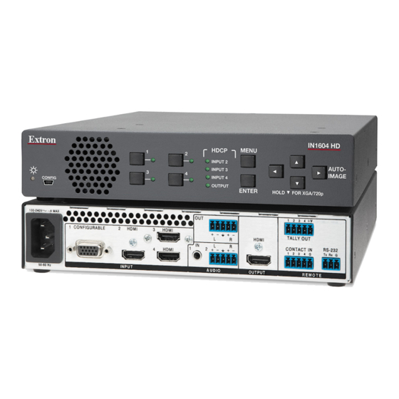
Installation This section contains information on how to connect cables to the scalers. Topics in this section include: • Rear Panel Connections • Connection Details Rear Panel Connections The IN1604 DTP and IN1604 HD have many of the same connectors. Figure 2 shows the different output connectors and the different arrangement of the remote connectors on the scalers. -
Page 13: Power And Input Connections
Power and Input Connections IN1604 DTP 100-240V ~ 0.5 A MAX Audio Plugs.eps OUTPUT 4 +V 1 CONFIGURABLE HDMI HDMI CONTACT IN TALLY OUT LINK OVER TP RS-232 HDBT RS-232 IR Tx Rx G HDMI INPUT AUDIO REMOTE Tip (+) 50-60 Hz Figure 3. -
Page 14: Output Connections
Output Connections IN1604 DTP 100-240V ~ 0.5 A MAX OUTPUT 4 +V 1 CONFIGURABLE HDMI HDMI CONTACT IN TALLY OUT LINK OVER TP RS-232 HDBT RS-232 IR Tx Rx G HDMI INPUT AUDIO REMOTE 50-60 Hz IN1604 HD 100-240V ~ 0.5 A MAX 100-240V ~ 0.5 A MAX 4 +V CONFIGURABLE... - Page 15 ATTENTION: • Do not connect this connector to a computer or telecommunications network. • Ne connectez pas ce port à des données informatiques ou à un réseau de télécommunications. • DTP remote power is intended for indoor use only. No part of the network that uses DTP remote power should be routed outdoors.
-
Page 16: Control Connections
Control Connections IN1604 DTP 100-240V ~ 0.5 A MAX OUTPUT 4 +V 1 CONFIGURABLE HDMI HDMI CONTACT IN TALLY OUT LINK OVER TP RS-232 HDBT RS-232 IR Tx Rx G HDMI INPUT AUDIO REMOTE 50-60 Hz IN1604 HD 100-240V ~ 0.5 A MAX 100-240V ~ 0.5 A MAX 4 +V 1 CONFIGURABLE... -
Page 17: Connection Details
Connection Details Analog Video Wiring Pinout Table for 15-pin HD Connectors RGBHV RGBs Component S-video Composite Green Green Luma Video Blue Blue Chroma H Sync Return C Sync Return Red Return Red Return R-Y Return Green Return Green Return Y Return L Return Video Return Blue Return... -
Page 18: Twisted Pair Recommendations For Dtp Communication
Twisted Pair Recommendations for DTP Communication Use the following pin configurations for twisted pair cables. Pins: T568B 12345678 T568A T568B Wire Color Wire color Wire color White-orange White-green White-orange Green Orange Orange White-orange White-green White-green Blue Blue Blue White-blue White-blue Orange Green White-blue... -
Page 19: Operation
Operation This section contains information on the front panel operation, On-screen Display Menu System, and reset modes of the scalers. Topics in this section include: • Front Panel Overview • Powering Up Input Selection • • Output Resolution Change Auto-Image from the Front Panel •... -
Page 20: Powering Up
Powering Up When power is applied to the scaler, the Input selection buttons light green before illuminating just the selected input. Input Selection Press any of the Input selection buttons on the front panel to select an input. Output Resolution Change When the On-screen Display (OSD) menu system is not active, press and hold (for about 5 seconds) the ) button to toggle between 1024x768 @ 60 Hz and 720p @ 60 Hz... -
Page 21: On-Screen Display (Osd) Menu System
On-Screen Display (OSD) Menu System The OSD menu is used primarily when the scaler is initially set up. Configuration and adjustments can also be performed with SIS commands (see SIS Configuration and Control on page 29) or the Product Configuration Software (see Configuration Software on page 49). - Page 22 To navigate the OSD menu: Press the button to navigate the nine submenus. The following table shows Down the nine submenus and their respective submenu items. Submenus Submenu Items Quick Setup Auto-Image Input Format EDID Audio Output Aspect Ratio Audio Mute Test Pattern Resolution User Presets...
-
Page 23: Quick Setup Submenu
Quick Setup Submenu Figure 11. Quick Setup Submenu submenu allows quick access to common input, output, and Quick Setup communication settings. This submenu contains the following submenu items: Auto-Image — Press the button to execute an Auto-Image on the current input (see Enter Auto-Image on page 20). -
Page 24: User Presets Submenu
User Presets Submenu Figure 12. User Presets Submenu submenu allows the current picture control settings (see Picture User Presets Controls Submenu on page 19) for the selected input to be saved, a user preset to be recalled, or a user preset to be erased. User presets can be saved and recalled later on another input, allowing them to also be used as aspect ratio or discrete size and center shortcuts. -
Page 25: Picture Controls Submenu
Picture Controls Submenu Figure 13. Picture Controls Submenu submenu allows adjustment of picture settings. Picture Controls NOTE: Picture control settings are saved in user presets (see User Presets Submenu on page 18). They are also saved in input presets along with other settings. To save and recall input presets, use SIS commands (see Preset Commands on page 40) or... -
Page 26: Input Submenu
Input Submenu Figure 14. Input Submenu submenu allows adjustment of the active input. Input Auto-Image — Press the button to execute an Auto-Image on the active input. Enter Auto-Image updates active pixel, active lines, horizontal and vertical start, phase, horizontal and vertical image position, and horizontal and vertical image size settings. - Page 27 Input Format — Press the navigation buttons to select an analog video input format for inputs 1 and 2. All other inputs are digital inputs for HDMI or DVI input signals. The following table shows the available formats for each input. Input 1 Input 2 Input 3...
-
Page 28: Output Submenu
Output Submenu Figure 15. Output Submenu submenu allows configuration of the output resolution, refresh rate, HDMI Output format, and HDCP notification. IN1604 DTP and IN1604 HD Scalers • Operation... - Page 29 Output Resolution — Press the navigation buttons to change the resolution and refresh rate from the select list. The table on page 21 shows the available resolution and refresh rates. Resolution 23.98 Hz 24 Hz 25 Hz 29.97 Hz 30 Hz 50 Hz 59.94 Hz 60 Hz...
-
Page 30: Audio Submenu
Audio Submenu Figure 16. Audio Submenu submenu allows adjustment of audio settings, including mute, input format, gain Audio and attenuation, output format, and volume. Audio Mute — Press the navigation buttons to globally mute or unmute audio output. Audio Format — Press the navigation buttons to select the audio input format. Input 1 can only be set to , or . -
Page 31: Advanced Submenu
Advanced Submenu Figure 17. Advanced Submenu submenu allows adjustment of test patterns, screen saver mode, automatic Advanced Auto-Image, aspect ratio, auto memory, overscan settings, auto switch, and factory reset. Test Pattern — Press the navigation buttons to select a test pattern to display or to turn off a test pattern. - Page 32 Screen Saver and Timeout — Press the buttons to select the screen Left Right saver setting: (default) or . Press the buttons to set the duration (in Black Blue Down seconds) the screen saver remains active before sync is disabled. When there is no active video on the selected input, the device can mute the video output to black or blue for a set duration before disabling output sync.
-
Page 33: Communication Submenu
Overscan — Press the navigation buttons to select the overscan value for each input format. Choose between , or . Set default overscan mode through SIS 2.5% Overscan mode commands (see the SIS commands on page 45). Overscan is specific to each input signal type. This feature zooms and crops SMPTE input resolutions to mask edge effects and ancillary data that are common in broadcast signals. -
Page 34: Device Info Submenu
Remote Port — Displays the Baud rate for the serial RS-232. Contact Mute and Tally LED — Press the buttons to select contact Left Right closure mute mode. Press the buttons to select the tally LED action. Down Contact Mute options: •... -
Page 35: Sis Configuration And Control
SIS Configuration and Control The scaler can be configured and controlled with Extron Simple Instruction Set (SIS) commands when connected to a host computer or other device (such as a control system). Attach the host device to the rear panel RS-232 connector or the front panel USB port. Commands can be entered using a Telnet application such as the Extron DataViewer, available at www.extron.com... -
Page 36: Sis Overview
SIS Overview Using the Command and Response Tables Command and Response Tables for SIS commands beginning on page 35 lists the commands that the scaler recognizes as valid, the responses that are returned to the host, a description of the command function or the results of executing the command, and examples of commands in ASCII (Telnet) and URL encoded (Web). - Page 37 = Enable or disable = off or disabled = on or enabled = Input standard = no signal detected on the current input = NTSC 3.85 = PAL = NTSC 4.43 = SECAM = Not applicable (occurs when the input is active RGB, YUV, or HDMI signal) = Internal temperature In degrees Celsius...
- Page 38 = Screen saver mode = black output (default) = blue output with OSD text = Video output mute = unmute = mute video = mute video and sync = Auto-Image threshold value (where = black and = white; 0-100 = default) = HDCP status = no sink or source device detected = sink or source detected with HDCP...
- Page 39 = Screen saver status = active input detected, timer not running = no active input, timer running, output sync still active = no active input, timer expired, output sync disabled = HDCP authorization status = block HDCP encryption = allow HDCP encryption (default) = DTP output format = DTP format (default) = HDBaseT format...
- Page 40 = EDID emulation or output = automatic (matches the current output rate resolution; default) = output (available for EDID export only) = custom EDID or output rate 1 = custom EDID or output rate 2 = custom EDID or output rate 3 = custom EDID or output rate 4 = custom EDID or output rate 5 SIS Variables for EDID Resolution and Refresh Rate Combinations (where...
-
Page 41: Command And Response Tables
Command and Response Tables Command ASCII Command Response Additional Description (host to scaler) (scaler to host) Input Configuration Commands Input selection Select input X! • Select input View current input View the current input. Input video format Set video format Set input to format View set format... -
Page 42: Horizontal Or Vertical Start
Command ASCII Command Response Additional Description (host to scaler) (scaler to host) Horizontal start Specify a value Set the horizontal start position. E X# HSRT Hsrt Increment value Increase the horizontal start +HSRT Hsrt position by one. Decrement value Decrease the horizontal start -HSRT Hsrt position by one. - Page 43 Command ASCII Command Response Additional Description (host to scaler) (scaler to host) Active pixels Specify a value E X& X&] X& Set the active pixels to on the current input. APIX Apix Increment value Increase the active pixels by one on the X&] +APIX Apix...
-
Page 44: Picture Adjustment Commands
Command ASCII Command Response Additional Description (host to scaler) (scaler to host) Picture Adjustment Commands Contrast Specify a value E X1$ X1$] Set the contrast for the current input. CONT Cont Increment value X1$] Increase the contrast setting by one. +CONT Cont Decrement value... - Page 45 Command ASCII Command Response Additional Description (host to scaler) (scaler to host) Horizontal shift (image) Specify a value E X1% X1%] Set the horizontal position to HCTR Hctr Increment value Increase the horizontal position X1%] +HCTR Hctr setting by one. Decrement value Decrease the horizontal position X1%]...
-
Page 46: Preset Commands
Command ASCII Command Response Additional Description (host to scaler) (scaler to host) Preset Commands User presets Recall preset X2)] Recall user preset 1Rpr Save preset X2)] Save the current picture controls. 1Spr Delete preset X2)] Clear user preset PRST PrstX1* User preset name Write name X1#]... -
Page 47: Output Configuration Commands
Command ASCII Command Response Additional Description (host to scaler) (scaler to host) Output Configuration Commands TMDS output format Set format E X3$ X3$] Set the color space and format of the VTPO Vtpo output to View setting X3$] View the color space and format setting. VTPO X3$] Verbose mode 2 and 3... - Page 48 Command ASCII Command Response Additional Description (host to scaler) (scaler to host) Video mute (defaults to unmuted after a power cycle) Mute video to black Mute the video and display a black Vmt1 screen. Mute output sync/video Mute the video and sync on all outputs. Vmt2 Unmute output Display the selected input.
-
Page 49: Audio Configuration Commands
Command ASCII Command Response Additional Description (host to scaler) (scaler to host) Audio Configuration Commands Output audio mute Enable global audio mute Enables audio mute on all outputs. Amt1 Disable global audio mute Disable audio mute on all outputs. Amt0 Set discrete audio mute Set audio mute on output View output audio mute... -
Page 50: Advanced Configuration Commands
Command ASCII Command Response Additional Description (host to scaler) (scaler to host) Volume Set volume Set the volume. X3^] Increment the volume Increase the volume by 1 dB. X3^] Decrement the volume Decrease the volume by 1 dB. X3^] View the volume setting X3^] View the volume level. -
Page 51: Rgb = Yuv
Command ASCII Command Response Additional Description (host to scaler) (scaler to host) Input aspect ratio (per input) Set for fill Fill the entire output. E X! *1ASPR Aspr Set to follow Maintain the input aspect ratio. E X! *2ASPR Aspr View aspect setting View the aspect ratio setting. - Page 52 Command ASCII Command Response Additional Description (host to scaler) (scaler to host) Auto switch mode Disable auto switch mode Manual input switching only. 0AUSW Ausw0 Prioritize highest active Automatically switches to the 1AUSW Ausw1 input highest numbered active input. Prioritize lowest active Automatically switches to the lowest 2AUSW Ausw2...
-
Page 53: On-Screen Menu Configuration Commands
Command ASCII Command Response Additional Description (host to scaler) (scaler to host) On-Screen Menu Configuration Commands Front control panel emulation Toggle menu Toggle the OSD menu on or off. MMENU Menu*M Enter menu Enter OSD menu. AMENU Menu*A Exit menu Exit OSD menu. - Page 54 Command ASCII Command Response Additional Description (host to scaler) (scaler to host) Information request General Information X! • X@ • X1) • X( • X2( • X1@ • X1@] Query firmware version View firmware version. x.xx Query full firmware version View full firmware version.
-
Page 55: Configuration Software
Configuration Software The Extron Product Configuration Software (PCS) offers another way to control the scalers via USB connection in addition to the SIS commands. This section describes the software installation and communication (see the IN1604 Series Product Configuration Software help file for additional control information). Topics in this section include: •... -
Page 56: Software Connection
On the Extron website, select the tab (see figure 22, Download From the left sidebar, click the link ( Click the button. Download Submit any required information to start the download. Note where the file is saved. Open the executable (.exe) file from the save location. Follow the instructions that appear on the screen. -
Page 57: Device Discovery Panel
Device Discovery Panel panel displays accessible Extron devices connected directly to the Device Discovery PC using the software. Devices can be identified and sorted by model, IP address, device name, or connection method. Figure 24. Device Discovery Panel To sort the list of available devices: Click the tab (see figure 24, Device Discovery... -
Page 58: Offline Device Preview
Offline Device Preview The configuration options for scalers can be viewed without connecting to a device, but the settings cannot be changed or saved. To open a scaler device tab: In the drop-down menu, select . The Start-up New Configuration File dialog box opens. -
Page 59: Software Overview
Software Overview Figure 27. Online Device Tab (IN1604 DTP Shown) Each device tab has a drop-down menu to the right of the device name for Device device-specific configuration options. The menu in the top right corner provides Software software configuration and information options for PCS and is available to all device modules. Software Menu menu contains options to display device connection methods in the device Software... -
Page 60: Software Settings
Software Settings This option resets all disabled confirmation dialogs to the default settings. From the , select . The Software Menu Software Settings Software Settings dialog box opens. Figure 30. Software Settings Dialog Box Click the button. The dialog box closes and the Re-enable Confirmation Dialogs reset is complete. -
Page 61: Device Menu
Exit This option disconnects PCS from connected devices and closes the application. From the menu, select . If device tabs are open, the dialog box Software Exit Exit opens. Figure 32. Exit Dialog Box If necessary, click the button to disconnect the software Close Session(s) and Exit from connected devices, close all offline device tabs, and close the software. -
Page 62: Reset Device
Unit Information tab tab displays basic information about the connected device. Unit Information Figure 34. Unit Information Tab (IN1604 DTP Shown) Click the button ( ) to close the dialog box. Cancel Reset Device This option opens a dialog box to confirm the resetting of device settings. From the drop-down menu, select . - Page 63 Backup option exports all audio, video, and communication settings of the connected Backup device to the PC. This exported configuration can be saved as a backup, or be used to replicate settings from one device to other devices of the same model. When restoring a configuration, specific device settings can be selected.
-
Page 64: Update Firmware
Update Firmware This option uploads firmware from the host device to the connected device. NOTE: If necessary, download new firmware from the Extron website to the host device (see Downloading Updated Firmware on page 79). From the drop-down menu, select . -
Page 65: Av Controls Panel
AV Controls Panel panel is used to control AV settings such as input selection, one-time AV Controls Auto-Image to an input, video and audio mute, and image freeze. The panel also displays input and output information. Figure 39. AV Controls Panel AV Inputs Buttons Click an input button from the panel (... -
Page 66: Configuration Pages
Configuration Pages The configuration pages contain options for input and output configuration, EDID management, image settings, image size and position, audio configuration, preset management, and general settings. Figure 40. Global Navigation Bar Input and Output Configuration Page To open this page, click the icon ( ) on the Input/Output Config... - Page 67 Input Configuration panel Figure 42. Input Configuration Panel To configure an input, adjust the following: For analog input 1, select the desired input signal type from the Signal Type drop-down menu ( ). Available options include (default), , and S-Video .
- Page 68 Output Configuration panel panel contains controls for output resolution and rate, format Output Configuration settings, switch transitions, and available test pattern selections. Figure 43. Output Configuration To configure the output, perform the following: From the drop-down menu ( ), select the desired output resolution. Resolution From the drop-down menu (...
-
Page 69: Edid Minder Page
EDID Minder Page EDID Minder is an EDID management process that manages the EDID information between the scaler and one or more input sources. Click the icon (see figure EDID Minder on page 60) on the to open the page. Global Navigation Bar EDID Minder Figure 45. - Page 70 Assigning EDID To assign EDID to selected inputs: From the inputs group box (table of inputs) on the right, select the check boxes for the desired inputs (see figure on page 63). From the , or pane ( ) on the Favorites Connected Outputs Available EDID...
-
Page 71: Image Settings Page
Image Settings Page From this page, signal sampling and picture control settings can be adjusted, user and input presets can be saved and recalled, and overscan settings can be applied. Click the Image icon (see figure on page 60) on the to open Settings Global Navigation Bar... - Page 72 Picture Controls panel panel shows adjustable image settings for the selected input. Pictures Controls Figure 48. Picture Controls Panel To adjust the picture settings, click and drag the associated slider for any applicable image setting (brightness, contrast, color, tint, or detail) to the desired value. Alternatively, enter a value within the field associated with the image setting, or click the arrows to change the value in the field.
- Page 73 Preset panels overview Presets save output settings to be recalled (see the following table for a comparison of saved settings for input and user presets). Settings Included Within Presets Setting User Preset Input Preset Horizontal and Vertical Start Active Lines Pixel Phase Active Pixels Total Pixels...
-
Page 74: User Presets
Input presets There are 16 presets that are global to all inputs. The presets contain all of the settings for an input when used with an upstream matrix switcher. Input presets save signal type, signal sampling, and picture control settings. To save an input preset: From the list (see... -
Page 75: Size And Position Page
Size and Position Page page provides three methods of adjusting image output size and Size and Position position: graphically, numerically, or automatically with Auto-Image. Click the Size and icon (see figure on page 60) on the to open Position Global Navigation Bar page. -
Page 76: Audio Configuration Page
Audio Configuration Page From the page, audio inputs and outputs can be configured and mixed. Audio Config Click the icon (see figure on page 60) on the Audio Config Global Navigation to open this page. Figure 52. Audio Configuration Page From the drop-down menu (see figure 52, ), select the desired audio... - Page 77 — The digital input is configured to receive • LPCM-2Ch Auto (Analog 1) 2-channel LPCM audio. If 2-channel LPCM audio is not detected, the input switches to analog input 1 to send to the output. This option sets 2Ch audio EDID. —...
-
Page 78: Preset Management Page
Preset Management Page page gives access to input and user presets. Click the Preset Management Preset icon (see figure on page 60) on the to open Management Global Navigation Bar page. Preset Management Figure 53. Preset Management Page For information on presets, see Preset panels Overview on page 67. -
Page 79: General Settings Page
To clear a preset: Select the input preset or user preset (see figure on page 72) to be cleared. Click the button ( ) located in the same section of the screen. A confirmation Clear dialog box opens. Click the button to erase saved data or click the button to return to the Clear... - Page 80 Screen Saver panel When no active video is detected on the selected input, the screen saver mode is activated. The output sync can be disabled after a user-set duration, which allows display devices to go into a low power, standby state. Figure 55.
- Page 81 Contact Mute and Tally LED panel Figure 57. Contact Mute and Tally LED Panel The Tally LED options are only available if contact mute is set to A/V Mute Sync Mute Contact Mute options: • — The initial contact closure provides input switching to the corresponding input. None Any additional button presses or contact closures on the input have no additional effect.
- Page 82 Auto Switch panel Auto switch mode automatically switches inputs based on detected input signals. Figure 59. Auto Switch Panel Select the check box to enable auto switch mode. Enable Auto Switch Click the radio button of the desired type of auto switch mode from the following: —...
-
Page 83: Reference Information
Reference Information This section contains reference or supplemental information. Topics in this section include: Mounting • • Downloading Updated Firmware Mounting Tabletop Mounting Attach the provided rubber feet to the bottom four corners of the enclosure. Rack Mounting The scalers can be mounted into racks with the pre-installed rack ears (see UL Guidelines for rack mounted devices on page 78). -
Page 84: Furniture Mounting
UL Guidelines for rack mounted devices The following Underwriters Laboratories (UL) guidelines pertain to the safe installation of the scaler in a rack. Elevated operating ambient temperature — If the equipment is installed in a closed or multi-unit rack assembly, the operating ambient temperature of the rack environment may be greater than room ambient temperature. -
Page 85: Downloading Updated Firmware
Downloading Updated Firmware Figure 63. Downloading Firmware from the Extron Website On the Extron website, click the tab ( Download From the left sidebar, click the link ( Firmware Navigate to the IN1604 DTP or IN1604 HD ( Ensure the available firmware version is a later version than the current one on the device. -
Page 86: Extron Warranty
Extron Electronics makes no further warranties either expressed or implied with respect to the product and its quality, performance, merchantability, or fitness for any particular use. In no event will Extron Electronics be liable for direct, indirect, or consequential damages resulting from any defect in this product even if Extron Electronics has been advised of such damage.