Extron electronics IN1804 Series User Manual
Seamless scaling switchers
Hide thumbs
Also See for IN1804 Series:
- Setup manual (4 pages) ,
- User manual (110 pages) ,
- Setup manual (4 pages)

Related Manuals for Extron electronics IN1804 Series


Summary of Contents for Extron electronics IN1804 Series
- Page 1 User Guide Scalers IN1804 Series Seamless Scaling Switchers 68-3274-01 Rev. C 01 20...
- Page 2 Safety Instructions Safety Instructions • English Istruzioni di sicurezza • Italiano AVVERTENZA: Il simbolo, , se usato sul prodotto, serve ad WARNING This symbol, , when used on the product, is intended to avvertire l’utente della presenza di tensione non isolata pericolosa alert the user of the presence of uninsulated dangerous voltage within the all’interno del contenitore del prodotto che può...
- Page 3 Copyright © 2018-2020 Extron Electronics. All rights reserved. www.extron.com Trademarks All trademarks mentioned in this guide are the properties of their respective owners. The following registered trademarks ( ® ), registered service marks ( ), and trademarks ( ) are the property of RGB Systems, Inc. or Extron Electronics (see the current list of trademarks on the...
- Page 4 FCC Class A Notice This equipment has been tested and found to comply with the limits for a Class A digital device, pursuant to part 15 of the FCC rules. The Class A limits provide reasonable protection against harmful interference when the equipment is operated in a commercial environment.
- Page 5 Conventions Used in this Guide Notifications The following notifications are used in this guide: CAUTION: Risk of minor personal injury. ATTENTION : Risque de blessure mineure. ATTENTION: Risk of property damage. • • Risque de dommages matériels. NOTE: A note draws attention to important information. TIP: A tip provides a suggestion to make working with the application easier.
-
Page 7: Table Of Contents
Contents Introduction Front Panel Lockout (Executive Modes) .... 41 ........... 1 Input Presets ............ 42 About this Guide ..........1 Reset Modes ............ 42 Product Description ..........1 RS-232 and IR Signal Insertion ......43 Models ............1 Ethernet to RS-232 Insertion ......44 Integrated Digital Twisted Pair Extension .. - Page 8 Internal Web Page ..........92 Accessing the Web Page ........92 Disabling Compatibility Mode ......93 Web Page Components ........94 Device Info Panel .......... 95 Inputs Panel..........95 Roles and Permissions Panel ......96 Device Status Panel ........97 Outputs Panel ..........
-
Page 9: Introduction
DTP2 extension of video, audio, and control signals up to 330 feet (100 meters) over a shielded CATx twisted pair cable. The IN1804 Series also provide automatic switching, audio embedding and de-embedding, seamless transition effects, and logo keying. Designed for professional AV integration, the IN1804 can be controlled and configured via Ethernet, RS-232, USB, and contact closure with tally outputs. -
Page 10: Integrated Digital Twisted Pair Extension
Integrated Digital Twisted Pair Extension The DTP2 inputs and outputs are proprietary signals that are created within any of the Extron DTP Extender systems and transmitted over a single shielded twisted pair (STP) cable. The IN1804 accepts DTP inputs from transmitting devices such as the DTP T USW 333. - Page 11 Advanced Extron Vector 4K scaling engine — The Vector 4K scaling engine is • specifically designed for critical-quality 4K imagery, with best-in-class image upscaling and downscaling. • Supports signal resolutions up to 4K @ 60 Hz with 4:4:4 color sampling. •...
- Page 12 RS-232 insertion from the Ethernet control port — Saves system resources • and simplifies installation by enabling a control processor to access remote RS-232 devices over Ethernet. Additional analog stereo audio signals accepted — IN1804 DI, IN1804 DO, • and IN1804 DI/DO support stereo analog audio signals for simultaneous transmission over the same shielded twisted pair cable.
- Page 13 Automatic 3:2 and 2:2 pulldown detection — Advanced film mode processing • techniques help maximize image quality for content sources that originated from film. Auto-Image setup — When Auto-Image is activated, the unit automatically optimizes • the image by analyzing and adjusting to the video input signal. •...
-
Page 14: Control Methods
The Extron Everlast Power Supply is covered by a 7-year parts and labor warranty. Control Methods Control the IN1804 series switchers using one or more of the following methods: • The front panel controls and the on-screen display (OSD) menu (see... -
Page 15: Application Diagrams
Application Diagrams The following diagrams show examples of typical applications for different IN1804 models. Extron Show Me Cable COM 1 COM 2 DIGITAL I/O IPCP PRO 250 Extron Extron Tx Rx RTS CTS Tx Rx IPCP Pro 250 POWER RELAYS eBUS IR/S Cable Cubby 500 CCB... - Page 16 Laptop Ethernet DisplayPort Extron 100-240V ~1.0A MAX IN R L OUT R RS-232 RESET IN1804 DO Tx Rx G Seamless Scaling LINK OVER TP Switcher Tx Rx G HDMI/CEC 50-60 Hz MODEL 80 HDMI HDMI HDMI HDMI/CEC CATx Cable up to 330' (100 m) Laptop FLAT PANEL...
-
Page 17: Installation
• PCS (see Configuration Software beginning on page 82 to download the • software, and see the IN1804 Series PCS Help File to configure the system) SIS commands (see SIS Configuration and Control, beginning on page 48) • IN1804 Seamless Scaling Switchers • Installation... -
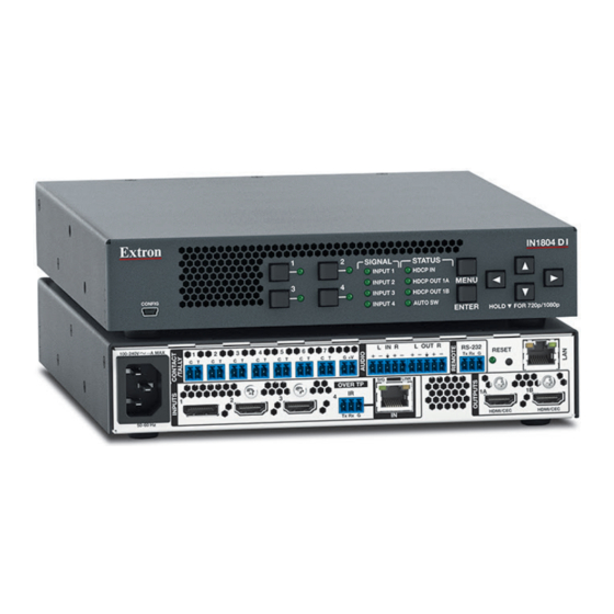
Page 18: Rear Panel Connections
Rear Panel Connections Figures 5 through 8 show the rear panels of the four IN1804 models: IN1804 (standard), IN1804 DI, IN1804 DO, and IN1804 DI/DO. 100-240V ~0.7A MAX IN R L OUT R RS-232 RESET Tx Rx G HDMI/CEC HDMI/CEC 50-60 Hz Figure 5. - Page 19 AC power connector HDMI mirrored output connectors — Outputs 1A and 1B (Standard and DI DisplayPort input connector — Input 1 models) HDMI input connectors — HDMI output connector — Output 1B Inputs 2-4 (standard and DO models) (DO and DI/DO models) Inputs 2-3 (DI and DI/DO models) LAN connector Over TP IR pass-through input port...
- Page 20 DTP2/XTP input connector (input 4, IN1804 DI and IN1804 DI/DO only) — Connect a DTP2 transmitter or XTP matrix switcher to this DTP IN RJ-45 connector to send and receive DTP or XTP signals over a single twisted pair cable (see Twisted Pair Recommendations for DTP2, XTP, and HDBaseT Communication on page 18 for...
- Page 21 ATTENTION: • Do not connect this connector to a computer or telecommunications network. • Ne connectez pas ce port à des données informatiques ou à un réseau de télécommunications. • DTP remote power is intended for indoor use only. No part of the network that uses DTP remote power should be routed outdoors.
- Page 22 When connected to an Ethernet LAN, the IN1804 can be accessed from a computer running a standard Internet browser. Use a patch or crossover cable to connect the IN1804 to a computer, control device, router, or switch. The default IP address of the switcher is 192.168.254.254, the default subnet mask is 255.255.255.0, and the default gateway address is 0.0.0.0.
- Page 23 Analog audio output connector — Connect a balanced or unbalanced audio output device to this 5-pole captive screw Audio Out connector (see Analog Audio Connections on page 16). ATTENTION: • For unbalanced audio, connect the sleeves to the ground contact. Do not connect them to negative (–) contacts (see the Extron Audio Wiring Card).
-
Page 24: Connection Details
Connection Details Analog Audio Connections Wire the audio input and output connectors as shown in figure 11. Use the supplied tie wrap to strap the audio cable to the extended tail of the connector. No Ground Here Ring Sleeves Sleeves Ring No Ground Here Balanced Audio Output... -
Page 25: Hdmi Connections
HDMI Connections Use an Extron LockIt cable lacing bracket to secure HDMI cables to the device. NOTE: The HDMI device must have an HDMI connection mounting screw for this bracket to be used. To securely fasten an HDMI cable to a device: Figure 12. -
Page 26: Twisted Pair Recommendations For Dtp2, Xtp, And Hdbaset Communication
Twisted Pair Recommendations for DTP2, XTP, and HDBaseT Communication Use the following pin configurations for shielded twisted pair cables used for DTP or HDBaseT communication. T568B Pins: 12345678 Wire Color White-orange Orange White-green Blue White-blue Green Insert Twisted Pair Wires White-brown RJ-45 Brown... -
Page 27: Wiring The Contact/Tally Connectors
C and to the shared pin G. If using a tally indicator, connect the indicator device to the shared +V pin and the T pin. See the IN1804 Series Help File for instructions on configuring these ports using PCS. IN1804 Seamless Scaling Switchers • Installation... -
Page 28: Connecting Using An Sm Cable
Connecting Using an SM Cable The Contact/Tally connectors can also be used with Extron SM cables. Figure 15 shows how to wire an SM cable to a contact input. Black Cable Figure 15. SM Cable Connecting Contact and Tally Ports For each SM cable: Connect the red (contact) pigtail to the C pin corresponding to the input being used. -
Page 29: Operation
Front Panel Lockout (Executive Modes) • Input Presets Reset Modes • • RS-232 and IR Signal Insertion Front Panel Overview All IN1804 Series models have the same front panels. IN1804 DO SIGNAL STATUS INPUT 1 HDCP IN INPUT 2 HDCP OUT 1A... -
Page 30: Powering Up
Powering Up When power is applied to the switcher, the Input 1 LED blinks prior to the full boot-up of the product. When boot-up is complete or nearing completion, each of the input LEDs lights, one at a time, in ascending order (1 through 4). Next, each of the signal status LEDs lights in the same manner. -
Page 31: Menu Overview
Menu Overview In the on-screen menu, the product name is displayed at the top of the right column. The active input and output resolutions are displayed in the bottom border. The on-screen menu contains eight submenus with various submenu items of adjustable settings or device information (see the Submenus table, below). -
Page 32: Using The Menu Screens
Using the Menu Screens Figure 18. On-screen Menu Example To open the on-screen menu: Connect a display device to an HDMI output connector (see Rear Panel Connections on page 10). Press the Menu or Enter button to open the on-screen menu. To navigate the on-screen menu: >... -
Page 33: Device Info Screen
To exit the on-screen menu system: From any menu screen, press the Menu button to close the on-screen menu and exit the system. Device Info Screen Figure 19. Device Info Screen The read-only Device Info screen is listed first in the submenus (left) panel. This screen contains information about your IN1804, including unit name, firmware version, internal temperature in Celsius and Fahrenheit, selected input device format and signal information, and output signal information for all outputs. -
Page 34: Quick Setup Submenu
Quick Setup Submenu Figure 20. Quick Setup Submenu The Quick Setup submenu is displayed by default when the OSD is first opened, and provides quick access to frequently-used settings. This submenu contains the following items, which also appear on other submenus in the system: INn: Input Mode —... -
Page 35: Picture Controls Submenu
Auto-Image SIS commands on page 61 or PCS (see the IN1804 Series PCS Help File). The options include to execute an Auto-Image and fill the output and to execute an Auto-Image and maintain the input aspect ratio. These commands ignore the current aspect mode setting, perform Auto-Image on the input, and then select Fill or Follow. - Page 36 • Image Position — Press the ƒ and „ buttons to select the horizontal (H) or > vertical (V) position of the image. Press the < buttons to adjust the value of the selected position. The ranges are: Horizontal position: -4096 through +4096 pixels. The default is 0000. •...
-
Page 37: Input Submenu
Input Submenu Figure 23. Input Submenu (IN1804 Standard and IN1804 DO) The Input submenu adjusts the active input. INn: Input Type — • On standard and DO models: Displays the format of the selected input • (read-only). On DI and DI/DO models: If input 4 (the DTP2/XTP input) is selected, use the •... - Page 38 INn:EDID — Press the navigation buttons to select an EDID for the active input. Select • a discrete EDID from a list of factory-supplied EDID or select Auto to use the current output resolution and refresh rate. The Input EDID Resolutions table below lists the available EDID selections, including their SIS command variable numbers (see the Input EDID commands...
- Page 39 • Capture EDID — Select this item to capture the EDID of the sink attached to the output and save it to one of the five custom EDID slots. The IN1804 assigns the captured EDID to its selected input. To capture an EDID: Select Capture EDID, then press Enter.
-
Page 40: Output Submenu
Output Rate — Select this item to specify the output resolution and refresh rate. The • IN1804 Series switchers have a range of resolutions from which to choose (see the Output Resolutions and Rates table on the next page for the available settings). The available rates depend on the selected resolution. - Page 41 Output Resolutions and Rates Resolution 23.98 Hz 24 Hz 25 Hz 29.97 Hz 30 Hz 50 Hz 59.94 Hz 60 Hz 640x480 800x600 1024x768 1280x768 1280x800 1280x1024 1360x768 1366x768 1440x900 1400x1050 1600x900 1680x1050 1600x1200 1920x1200 480p 576p 720p 1080i 1080p 2048x1080 (2K) 2048x1200 2048x1536...
- Page 42 67) or the Logo Config screen of the Logos commands PCS configuration program (see the IN1804 Series Help File) to assign a logo file to the selected slot. When a logo is assigned to a slot, its name changes from Unassigned to nn:Logo n.
-
Page 43: Audio Submenu
• Logo Position — This item lets you specify a position for the selected logo on the display relative to the upper-left corner of the logo. The default is H: 0000 V: 0000. To position the logo: Press the Enter button to select Logo Position from the Output submenu. The Logo Position item appears as a single field on the OSD. - Page 44 • INn: Audio Format — Select this item to choose the audio format for the selected input. The first item on the Audio menu shows the selected format of the audio. NOTES: • For the twisted pair inputs in DTP mode, the analog audio is taken from the analog audio connector on the DTP Tx.
-
Page 45: Advanced Submenu
Advanced Submenu Figure 27. Advanced Submenu The Advanced submenu enables you to configure the global settings for the unit. The following items are available: • Test Pattern — Lets you choose a test pattern to use in setting up a display when outputting different resolutions. - Page 46 Logo Position commands (see the Logo Horizontal Shift and Vertical Shift commands page 68) or PCS (see the IN1804 Series PCS Help File). Press Enter to confirm your selection. • Screen Saver Timeout — Lets you specify the number of seconds the selected screen saver is displayed before the output sync times out.
- Page 47 Auto Switch — Press the button to select the auto-input switch mode. Auto • Switch options are: Off (default) — Auto-input switching is disabled. Switching occurs only via the front • panel buttons or SIS commands. Last Connected — The IN1804 automatically switches to the most recently •...
-
Page 48: Communication Submenu
However, for 4K @ 60 Hz rate only, either the input resolution or the output resolution can be at 4K @ 60, but not both. For example, the input can be 4K @ 60 Hz with a 4K @ 30 Hz output and vice versa, but both the input and output cannot be 4K @ 60 Hz. -
Page 49: Front Panel Lockout (Executive Modes)
SIS commands (see the Front Panel Lock (Executive Mode) commands on page 75) and via PCS (see the IN1804 Series PCS Help file). All functions performed via USB, RS-232, or Ethernet remain available). •... -
Page 50: Input Presets
Input Presets The IN1804 Series switchers have 128 memory slots in which you can save input presets. These presets allow a matrix switcher with multiple types of video inputs (such as an XTP) to be placed upstream from the IN1804 to expand the number of video sources. -
Page 51: Rs-232 And Ir Signal Insertion
NOTE: The reset modes listed close all open IP and Telnet connections and all sockets. Each mode is a separate function, not a continuation from mode 1 to mode 5. Reset Mode Summary Mode Activation Result Purpose/Notes Using an Extron Tweeker or other small The device reverts to the factory default Use mode 1 to revert screwdriver, press and hold in the... -
Page 52: Ethernet To Rs-232 Insertion
Unidirectional RS-232 insertion via SIS commands (see Unidirectional RS-232 • Insertion via SIS Commands on page 47) — A control signal can be inserted to the RS-232 port of any connected twisted pair device via SIS commands sent to the IN1804. - Page 53 You also may need to set the RS-232 protocol of the addressed port to match the connected device. You can do this using any of the following methods: • Using the Product Configuration Software (see the IN1804 Series PCS Help file). • Using SIS commands (see the Serial Port Configuration SIS commands page 77).
-
Page 54: Captive Screw Ir Signal Insertion
Captive Screw IR Signal Insertion Figure 32 shows an example of a typical captive screw Ethernet insertion, in which an Extron control system provides IR control of a display via the switcher. Configure this type of insertion as follows: 100-240V ~ 50-60Hz PWR OUT = 12W T x R x G T x R x G Tx R x G Tx R x G RTS S G S G... -
Page 55: Unidirectional Rs-232 Insertion Via Sis Commands
Unidirectional RS-232 Insertion via SIS Commands Figure 33 shows an example of a typical connection for unidirectional RS-232 insertion via SIS commands. 100-240V ~ 50-60Hz PWR OUT = 12W T x R x G T x R x G T x R x G T x R x G RTS S G S G S G S G +V +S -S G... -
Page 56: Sis Configuration And Control
SIS Configuration and Control The IN1804 series switchers can be configured and controlled via Extron Simple Instruction Set (SIS) commands when connected to a host computer or other device (such as a control system). Attach the host device to the rear panel RS-232 connector or LAN connector, or to the front panel USB port. -
Page 57: Password Messages
Password Messages If the IN1804 is protected by a password, the following password message prompts you for the password to access the switcher features. ] Password ] The prompt requires a password, followed by a carriage return. The prompt is repeated if the correct password is not entered. -
Page 58: Switcher-Initiated Messages
Switcher-Initiated Messages When certain local events occur, such as a change in the status of a contact closure port, the switcher responds by sending a message to the host. No response is required from the host. The following messages may be sent: Reconfig ] A change in the current input frequency was detected. -
Page 59: Sis Overview
SIS Overview Using the Command and Response Tables Command and Response Tables for SIS commands, beginning on page 60, lists the commands that the switcher recognizes as valid, the responses that are returned to the host, a description of the command function or the results of executing the command, and examples of commands in ASCII (Telnet). - Page 60 Input selection — 1 through 4 = DisplayPort input 1 (all models) = HDMI or DVI input 2 (all models) = HDMI or DVI input 3 (all models) = HDMI or DVI input 4 (IN1804 standard, and IN1804 DO) TP (IN1804 DI and DI/DO) Output connector = TP Output 1A (IN1804 DO and DI/DO) HDMI output 1A (IN1804 and IN1804 DI)
- Page 61 EDID emulation or output rate = Automatic (matches the current output resolution, default) = Output 1A (available for EDID export only) = Output 1B (available for EDID export only) 10-76 = See the Input EDID table below. – = Custom EDID or output rates 1 – 5. Input EDID Resolution 23.98 Hz...
- Page 62 Test patterns = Off (default) = Crop = Alternating pixels = Crosshatch = Color Bars = Grayscale AUDIO = Audio test — Crop pattern with orbiting text TEST and outputting pink noise at LPCM-2Ch, 48 Hz, 24-bit. Input presets through Response is three digits, padded with zeros.
- Page 63 Verbose mode = None (default for LAN connection) = Verbose mode (default for RS-232 and USB connection) = Tagged responses to queries = Verbose mode and tagged responses NOTES: • In verbose response mode, the IN1804 returns unsolicited responses for value and setting changes that may result from a signal change, or a setting adjustment made via another interface.
- Page 64 Video switch effect = Cut through black — The input instantly cuts to black, then cuts to the newly selected input with no fading. = Fade through black — The input fades to black before the newly selected input fades in. = Seamless fade* (default) —...
- Page 65 Audio input format Format Details Selection None (input muted) —Configures input EDID with no audio support. All audio outputs are muted. Analog input — Configures input EDID with no audio support. Analog audio from the 5-pole captive screw input is passed to the 5-pole captive screw analog output and embedded into the HDMI output.
- Page 66 Power Save mode = Full power mode (default) = Lowest power state — TP remote power and TP links are disabled. Input LEDS 1 through 4 cycle at a 500 ms interval. = Lower power mode — TP links remain active, including remote power, and Ethernet to RS-232 insertion.
- Page 67 Unit name Unit name — A text string of up to 32 characters. • , and the hyphen ( ) are permitted. • The first character must be a letter. • The last character cannot be a hyphen. • Names are not case sensitive. •...
-
Page 68: Command And Response Tables For In1804 Sis Commands
Command and Response Tables for IN1804 SIS Commands Command ASCII Command Response Additional Description (Host to Switcher) (Switcher to Host) Input Configuration Input Selection X! ! In X! All ] Select input • Select input View current input View the current input. Input Video Format X! *\ View detected input format... - Page 69 Command ASCII Command Response Additional Description (Host to Switcher) (Switcher to Host) Input Configuration (continued) Auto-Image 1*0A Img1*0 ] Execute Execute an Auto-Image for the current input (follows the current aspect ratio). 1*1A Img1*1 ] Execute and fill Execute an Auto-Image and fill the output raster.
- Page 70 Command ASCII Command Response Additional Description (Host to Switcher) (Switcher to Host) Input Configuration (continued) Auto-input Switch Mode Set the auto-input switch EX3) X3)] AUSW Ausw Set the auto-input switch mode to mode View auto-input switch X3)] View current auto-input switch mode AUSW mode Set user priority order for...
- Page 71 Command ASCII Command Response Additional Description (Host to Switcher) (Switcher to Host) Picture Adjustments Freeze 1*1F Frz1*1 ] Enable Freeze the output on the screen. 1*0F Frz1*0 ] Disable Unfreeze the output. View X1)] Show the freeze status of the output. KEY: = On or Off status = Off or disabled...
- Page 72 Command ASCII Command Response Additional Description (Host to Switcher) (Switcher to Host) Picture Adjustments (continued) Horizontal Position (Shift) — Image Specific value X1^] Set the horizontal position of the image HCTR HctrI1* in relation to the top left corner of the output raster to Increment value X1^]...
- Page 73 Command ASCII Command Response Additional Description (Host to Switcher) (Switcher to Host) Output Configuration Output Video Mute Mute output video X@ * Mute video output Unmute output video X@ * Unmute video output Mute video and sync X@ * Mute video and sync on output View mute status X4@ ] View video mute status...
- Page 74 Command ASCII Command Response Additional Description (Host to Switcher) (Switcher to Host) Output Configuration (continued) TMDS Output Format Set output format EX@ * X4* X4*] Set the colorspace and format for HDMI VTPO Vtpo output View format setting EX@ VTPO } X4*] View the current output colorspace and format for output...
- Page 75 Command ASCII Command Response Additional Description (Host to Switcher) (Switcher to Host) Output Configuration (continued) Screen Saver * X4) Set mode X4)] Set the screen saver mode for the SSAV SsavM1* output to X4)] View mode M1 SSAV View the screen saver mode for the output.
- Page 76 Command ASCII Command Response Additional Description (Host to Switcher) (Switcher to Host) Logos (continued) Clear Logo Clear logo slot X4#] PRST PrstX3* Clear logo slot and change its name [unassigned] Logo Name E L X4# , X1$ X4# , X1$] Write name UNAM Unam L...
- Page 77 Command ASCII Command Response Additional Description (Host to Switcher) (Switcher to Host) Logos (continued) Logo Key Effect E X4# * Disabled 0 LKEF Lkef Disable key effect for logo Transparency E X4# * 1 LKEF Lkef Enable transparency for logo E X4# * RGB Key 2 LKEF...
- Page 78 Command ASCII Command Response Additional Description (Host to Switcher) (Switcher to Host) Presets Input Presets Values Saved in Input Presets Preset Name Detail Audio Gain and Attenuation H Image Position Film Mode Detection V Image Position Contrast H Image Size Brightness V Image Size Recall preset...
- Page 79 Command ASCII Command Response Additional Description (Host to Switcher) (Switcher to Host) Audio Configuration Audio Input Format Set input audio format Afmt X5@] AFMT Set the audio format for input View audio input format X5@] AFMT View audio input format for input NOTE: Digital auto modes 4 and 5 detect and use embedded digital audio when present.
- Page 80 Command ASCII Command Response Additional Description (Host to Switcher) (Switcher to Host) Audio Configuration (continued) Audio Output Mute Enable global audio mute Mute all audio outputs. Amt1 Disable global audio mute Unmute audio on all outputs. Amt0 Enable or disable discrete X1)] Set mute of audio output mute...
- Page 81 Command ASCII Command Response Additional Description (Host to Switcher) (Switcher to Host) Audio Configuration (continued) Configure Playback filename filename Set file-to-slot association ,< >CPLY Assign a file to slot . < > can include an optional path. <filename> ] CplyA NOTES: filename /Audio...
- Page 82 Command ASCII Command Response Additional Description (Host to Switcher) (Switcher to Host) Audio Configuration (continued) Transport Start and stop playback EX8) X8@] Start or stop the audio file playback. PLAY Play Unsolicited message sent when Play playback of file is complete. NOTE: Audio file slots are in order of priority, highest (slot 1) to lowest (slot 16).
- Page 83 Command ASCII Command Response Additional Description (Host to Switcher) (Switcher to Host) Advanced Configuration (continued) HDCP Output Mode Set HDCP mode X4^] HDCP HdcpS Set the HDCP output mode output View HDCP mode X4^] View the HDCP output mode for output HDCP HDCP Notification Set HDCP notification...
- Page 84 Command ASCII Command Response Additional Description (Host to Switcher) (Switcher to Host) Advanced Configuration (continued) Contact Port Status View individual contact port EX7% X7^] CNTC View the contact status of contact status port Verbose modes 2 and 3: X7^] Cntc View status of all contact X7^] CNTC...
- Page 85 Command ASCII Command Response Additional Description (Host to Switcher) (Switcher to Host) Advanced Configuration (continued) Resets NOTE: The remote power state for HDBT/XTP mode is forced to Off ( ). Attempts to change the power setting while the unit is not in DTP mode result in an (Not valid for current configuration) error message.
- Page 86 • Verbose modes 2 and 3: Seamless Scaling Switcher ] Inf02* • • View the IN1804 series description. n.nn ] Query firmware version View the firmware version to the second decimal place. Verbose modes 2 and 3: n.nn ] Ver01* Query full firmware version n.nn.nnnn ]...
- Page 87 Command ASCII Command Response Additional Description (Host to Switcher) (Switcher to Host) Information Requests (continued) Query part number X3^] View unit part number for the model. Verbose modes 2 and 3: X3^] E 20STAT } View internal temperature X1@] View unit internal temperature degrees Celsius.
- Page 88 Command ASCII Command Response Additional Description (Host to Switcher) (Switcher to Host) IP Control Port Commands (continued) IP Setup (continued) E CH } X9)] View MAC address View unit Media Access Code (MAC) address erbose modes 2 and 3: Iph • X9)] E 1* X8&...
- Page 89 Command ASCII Command Response Additional Description (Host to Switcher) (Switcher to Host) IP Control Port Commands (continued) Passwords ZQQQ NOTE: The initial passwords set at the factory are the serial number of the unit. However, if the unit is reset (via the Reset SIS command or the rear panel button), this password reverts to no password.
-
Page 90: Configuration Software
This section describes the software installation and communication (see the IN1804 Series PCS Help file for detailed control information). Topics in this section include: •... - Page 91 On the Extron website, select the Download tab (see figure , on the previous page). ) in the Downloads column and click it. Move the pointer to the Software link ( Figure 36. PCS Download Link On the Download Center page, click the P link (see figure 36, If necessary, scroll to locate PCS from the list of available software programs and click the Download link to the right of the name ( On the login page that appears next, fill in the required information to log into...
-
Page 92: Software Connection
Software Connection Open the Product Configuration Software program from the Start menu or desktop shortcut. The Extron Product Configuration Software window opens with the Device Discovery panel open. Connect to the switcher using the Device Discovery panel or the TCP/IP panel. Device Discovery Panel The Device Discovery panel displays accessible Extron devices connected directly to the PC or to a LAN or WAN. -
Page 93: Tcp/Ip Panel
Finalize the settings in one of the following ways: Click the Apply button to accept the changes and return to the Device • Discovery panel. Click the Apply and Connect button to accept the changes and connect to the • selected device. -
Page 94: Offline Device Preview
Offline Device Preview Opening a new device tab for an offline device displays the interface and configuration options for the chosen model without connecting to it. However, settings cannot be changed. To open a switcher device tab: From the Configuration File drop-down menu, select New Configuration File. Figure 39. -
Page 95: Software Overview
Figure 41 shows an example of an IN1804 DI/DO main screen. Figure 41. IN1804 DI/DO Main Window NOTE: For details about specific software features, see the IN1804 Series PCS Help file. Software Menu Each device screen has a Software drop-down menu for configuration options. This menu contains software and information options pertaining to PCS settings. - Page 96 Show Expanded Device Tabs This option displays the device IP address or connection method in the Device tab. From the Software menu, select Show Expanded Device Tabs. Figure 43. Expanded Device Tab (IN1804 Connected through USB) Software Settings This option resets all disabled confirmation dialogs to the default settings. From the Software menu, select Software Settings.
- Page 97 About Extron PCS This option contains information about the current PCS version. From the Software menu, select About Extron PCS. The About - Extron PCS dialog box opens. Figure 45. About - Extron PCS Dialog Box Click the Details button (see figure 45, ) for more information about the software.
-
Page 98: Device Menu
Device Menu The Device drop-down menu contains options pertaining to device connection, configuration, and information. For details about all these options, see the IN1804 Series PCS Help File. Figure 47. Device Menu Disconnect — Disconnects the PCS program from the connected device and closes •... - Page 99 • devices on the network. NOTE: The connected devices must be connected via LAN. IN1804 <model name> Help — Opens the IN1804 Series PCS Help file in a separate • window. About This Module — Opens About This Module dialog box, which contains the •...
-
Page 100: Internal Web Page
Internal Web Page The IN1804 Series switchers feature an internal web server, displayed as a web page. This page allows you to monitor and adjust certain settings of the IN1804 via a LAN or WAN connection. Use a web browser to view the pages on a PC connected to the switcher LAN port. -
Page 101: Disabling Compatibility Mode
Figure 48. IN1804 DI/DO Sign-in Page Enter Admin or User in the Username field (see figure 48, If required, enter the password in the Password field ( If no password has been set since the unit was delivered, enter the unit serial •... -
Page 102: Web Page Components
Web Page Components Device Info Panel Device Status Panel Network Settings Panel Inputs Panel Outputs Panel RS-232 Panel Roles and Firmware Panel Permissions Panel Figure 49. IN1804 Web Page NOTE: Figure 49 shows the web page for an IN1804 DI/DO model. The pages for the other three models are identical except for the product names and the contents of the Inputs and Outputs panels. -
Page 103: Device Info Panel
Device Info Panel The Device Info panel (see figure , on the previous page) displays device name, brief product description, and part number, with the option to edit the device name. The panel also contains an Extron link which opens the Extron website in a new window. -
Page 104: Roles And Permissions Panel
To view the status and type of all inputs, click the 3 More link in the lower-left corner of the Inputs panel (see figure , on page 94) to view the Inputs dialog box. Figure 51 shows an example of an IN1804 DO Inputs dialog box. Figure 51. -
Page 105: Device Status Panel
Click in the Confirm Admin Password field (see figure 52, ) and repeat the password from the Change Admin Password field. Figure 52. Passwords Dialog Box with Administrator Password Entered If you want to assign a user password, repeat steps 2 and 3 in the User panel ( When finished, click Save to set the passwords. - Page 106 Editing the date, time, and time zone Click the Edit link in the lower-left corner of the panel. The Edit Device Status dialog box opens. Figure 54. Edit Device Status Panel for Date and Time Setting Set the time, date, and time zone as desired: Date and Time —...
-
Page 107: Outputs Panel
Outputs Panel The Outputs panel (see figure , on page 94) displays the resolution and refresh rate of the outputs, their signal type, and the HDCP status of all connected outputs. The following status symbols may be displayed for connected outputs: Symbol Definition The display is HDCP compliant. -
Page 108: Network Settings Panel
During the updating process, a window appears in the middle of the screen, showing messages giving the progress of the update: Initializing, Installing the Firmware, and Rebooting Device. Figure 57. Firmware Update Message Window When the update is completed, the message window closes and the message Firmware Upload Complete appears near the top of the screen. -
Page 109: Rs-232 Panel
Edit the network settings as desired: DHCP — Click the DHCP button (see , on the previous page) to toggle • figure 58 DHCP on and off. When DHCP is enabled (On), the unit configures its IP address and other network settings from the DHCP server. The default is Off. IP Address, ( ), Subnet mask ( ), and Gateway address (... -
Page 110: Reference Information
Reference Information This section provides reference or supplemental information. Topics in this section include: Mounting • • Downloading Updated Firmware Licensed Third-Party Software Used in the Switchers • Mounting The IN1804 can be placed on a table or other furniture, mounted to a rack shelf, or mounted on or under furniture. -
Page 111: Furniture Mounting
Furniture Mounting The IN1804 can be mounted above or below a desk top, podium, or other furniture. Mounting kits are available at www.extron.com. Downloading Updated Firmware Figure 59. Downloading Firmware from the Extron Website On the Extron web page, click the Download tab (see figure 61, ) in the Downloads column and click it. -
Page 112: Licensed Third-Party Software Used In The Switchers
Licensed Third-Party Software Used in the Switchers The switchers use various licensed third-party software packages during operation. To view details about third-party packages and associated licensing, see the IN1804 Series PCS Help file. To view a copy of a listed package license, in the License Information dialog box, click the link in the License column for the relevant package. - Page 113 Extron Electronics makes no further warranties either expressed or implied with respect to the product and its quality, performance, merchantability, or fitness for any particular use. In no event will Extron Electronics be liable for direct, indirect, or consequential damages resulting from any defect in this product even if Extron Electronics has been advised of such damage.