Graco InvisiPac HM25 Operation, Repair, And Parts
Pattern controller
Hide thumbs
Also See for InvisiPac HM25:
- Instructions - parts (2 pages) ,
- Instructions - parts manual (126 pages)
Table of Contents
Advertisement
Quick Links
Operation, Repair and Parts
InvisiPac
Pattern Controller
To control fluid dispense valves of adhesive supply equipment. For professional use only.
Not approved for use in explosive atmospheres or hazardous locations.
See page 3 for model information and Agency approvals.
Important Safety Instructions
Read all warnings and instructions in this manual
and related manuals. Save these instructions.
®
334784G
EN
Advertisement
Table of Contents

Related Manuals for Graco InvisiPac HM25


Summary of Contents for Graco InvisiPac HM25
- Page 1 Operation, Repair and Parts ® InvisiPac 334784G Pattern Controller To control fluid dispense valves of adhesive supply equipment. For professional use only. Not approved for use in explosive atmospheres or hazardous locations. See page 3 for model information and Agency approvals. Important Safety Instructions Read all warnings and instructions in this manual and related manuals.
-
Page 2: Table Of Contents
Mirror Mode ......39 Graco Standard Warranty ....66... -
Page 3: Models
25M526 PC-8* Time or distance mode, no encoder Pattern controller * Order kit 17F712 to upgrade to PC-8e. Internal Models (HM25 and HM50) Used to upgrade InvisiPac HM25 and HM50 systems to include pattern control. Part Type Description Contents 24X640... -
Page 4: Warnings
Warnings Warnings The following warnings are for the setup, use, grounding, maintenance, and repair of this equipment. The exclama- tion point symbol alerts you to a general warning and the hazard symbols refer to procedure-specific risks. When these symbols appear in the body of this manual or on warning labels, refer back to these Warnings. Product-specific hazard symbols and warnings not covered in this section may appear throughout the body of this manual where applicable. - Page 5 Warnings WARNING SKIN JECTION HAZARD High-pressure fluid from dispensing device, hose leaks, or ruptured components will pierce skin. This may look like just a cut, but it is a serious injury that can result in amputation. Get immediate surgi- cal treatment. •...
- Page 6 Warnings WARNING TOXIC FLUID OR FUMES HAZARD Toxic fluids or fumes can cause serious injury or death if splashed in the eyes or on skin, inhaled, or swallowed. • Read Safety Data Sheets (SDSs) to know the specific hazards of the fluids you are using. •...
-
Page 7: Overview
Overview Overview InvisiPac pattern control systems can be integrated with InvisiPac systems or stand alone with any other equipment. For all installations, the advanced display module (ADM) is used to make programming easy. PC-8 controllers operate in time or distance mode without an encoder. Up to 8 guns and 4 independent triggers are supported. -
Page 8: Component Identification (Internal Models - Hm25C)
Component Identification (Internal Models - HM25c) Component Identification (Internal Models - HM25c) Installed onto InvisiPac System Run up Communication cable Power harness Valve Control board Trigger Cord grip Encoder 334784G... -
Page 9: Component Identification
Component Identification (Internal Models - HM25 and HM50) Component Identification (Internal Models - HM25 and HM50) Installed onto InvisiPac System Power supply Communication cable Power supply bracket Valve Power harness Trigger Control board Encoder Cord grip Run Up 334784G... -
Page 10: Component Identification (External Models)
Component Identification (External Models) Component Identification (External Models) Encoder Pattern controller Run up Power switch Inside view of pattern controller Communication cable Customer power board (not included) Ground terminal USB port Control board Valve Cord grips (I/O x2 power) Trigger 334784G... -
Page 11: Installation - Internal Models (Hm25C)
Installation - Internal Models (HM25c) Installation - Internal Models (HM25c) Connect Pattern Control Board 2. Remove cord grip assembly (T) from back of Invisi- Pac system and remove inserts. Inserts with grip tightly on most M8 and M12 cables and expand and 1. -
Page 12: Installation - Internal Models (Hm25 And Hm50)
Installation - Internal Models (HM25 and HM50) Installation - Internal Models (HM25 and HM50) Connect Pattern Control Board 2. Remove cord grip assembly (T) from pattern control board (S) and remove inserts. Inserts will grip tightly on most M8 and M12 cables and will expand and 1. -
Page 13: Module
Installation - Internal Models (HM25 and HM50) Connect Power Supply and Advanced Display Module NOTE: If the internal pattern controller is being installed 4. Connect communication cable (C) to open J3 con- into a first generation HM25 with DIN rail writing, addi- nector (or J6, if J3 is used) on MZLP board. -
Page 14: Install Control Board Into Invisipac System
Installation - Internal Models (HM25 and HM50) Install Control Board into 6. Connect power harness (P) to AWB terminal pins J1 and the input and output terminals of power supply. InvisiPac System 1. Mount board into open space on left-hand side of electrical enclosure. -
Page 15: Installation - External Models
Installation - External Models Installation - External Models Mounting Connect Advanced Display Module (ADM) The pattern controller and ADM can be mounted using the included VESA-compatible brackets and mounting software. Integrate with InvisiPac HM25c 1. Set pattern control system type selector switch to 0. 1. -
Page 16: Connect Pattern Control Board
Installation - External Models Integrate with InvisiPac (HM25 or HM50) Stand Alone 1. Set pattern control system type selector switch to 0. 1. Set the pattern control system type selector switch to 1. NOTE: The system must be powered off for a change in system type to have an effect. -
Page 17: Connect Electrical Cord
Installation - External Models Connect Electrical Cord 2. Connect earth ground to the grounding terminal. 3. Verify that the cord grip securely tightens around the power cord. Use a wrench to tighten, if necessary. Improper wiring may cause electric shock or other serious injury if work is not performed properly. -
Page 18: Wire Pattern Control Board
Wire Pattern Control Board Wire Pattern Control Board Valve Installation Trigger Installation 1. Connect up to 4 NPN, PNP, or dry contact triggers. NOTE: Supplied voltage (+) is 24 VDC 1. Connect up to 8 valves. 2. Connect the two wires between TR and minus (-) to NOTE: Control voltage is 24 VDC with a limit of 1 install a dry contact. -
Page 19: Plc Inputs And Outputs Installation (Optional)
Wire Pattern Control Board PLC Inputs and Outputs Installation (optional) Functions: Type Function Description Input ENABLE Turns the controller on and off (rising edge enables, falling edge disables). Integrated systems: Turn the heat on/off using the InvisiPac PLC input (instead of this input). The pattern controller will be turned on by the InvisiPac system once the InvisiPac goes inactive. -
Page 20: Encoder Installation
These are not used and do not need to be con- nected. NOTE: Encoder direction can be reversed by swap- ping A and A’ with B and B’. Do this is the line speed reads negative on the ADM. Graco Encoder Wiring Diagram Terminal Function Wire Color Plus... -
Page 21: Initial Startup
Initial Startup Initial Startup Software Update Key Token When integrating into an InvisiPac system, the system For PC-8e models only, a key token is required to may require a software update in order to be compatible enable encoder and run up use. with the pattern controller. -
Page 22: Screens
Screens Screens Navigate through each screen to set up the pattern controller interface. • Run screens include the home page and pattern definition. • Setup screens contain configurable settings for each accessory. Screen Maps NOTE: On integrated InvisiPac system, additional chapters are present for hot melt HMI. Run Screens PC Control PC Home... -
Page 23: Hmi Interface
Screens HMI Interface Function Controller enable/disable Stop all system processes Defined by icon next to soft key Abort current operation Accept change, acknowledge error, select item, toggle selected item Toggle between run and setup screens Navigate within a screen or to a new screen NOTICE To prevent damage to soft key buttons, do not... -
Page 24: Pc Screens
Screens PC Screens Home Read-only view of pattern controller inputs and outputs: 1. Status of guns , triggers , and PLC signals. 2. Production rate , and units completed 3. Material dispensed per product A - Gun states B - Trigger states C - Line information D - PLC signals Icon... - Page 25 Screens Program Storage (Screen 1) 1. Select program to load. 2. Copy program , erase program , or rename program 3. Purge guns 4. Lock/unlock controller for maintenance NOTE: Copy, erase, and rename capabilities are disabled if “Lock Pattern Definition” is enabled. See General Setup, page 32.
- Page 26 Screens Gun Purge 1. Purge individual guns 2. Purge all guns by pressing enter NOTE: Only guns with assigned triggers will purge. NOTE: Guns may only be purged when the system is active or within 5 minutes of the system being active. A - Press to purge B - Disabled guns will not purge Icon...
- Page 27 Screens Pattern Definition (Screen 2) 1. Enter start point and length of beads. 2. Enable or disable stitching for each bead. 3. Preview this pattern. NOTE: To clone the pattern from gun A to gun B, navigate to any bead on gun B and press/hold the number key for gun A.
- Page 28 Screens Pattern Preview Read-only display of bead pattern. A - Endpoint of last bead B - Exit preview - Gun number - Trigger number NOTE: Dotted pattern shows stitching. The actual number of stitched bead sis not represented. NOTE: A red pattern indicates that the gun does not have a trigger selected. See Event Map, page 29. 334784G...
- Page 29 Screens Event Map (Screen 1) Enter configuration settings for this pattern: 1. Assign trigger to each gun. 2. Enter gun trigger offset. 3. Enter minimum product length (if false trigger pickup is a concern). 4. Enable pattern mirroring. 5. Enter stitch percentage and interval. A - Enter screen B - Gun number C - Trigger for gun...
- Page 30 Screens Line Mode (Screen 2) 1. Select mode: b. Adjust line speed setting until length of last a. Time based. product is correct. b. Distance mode without encoder (uses fixed line 4. For distance mode with encoder: speed). a. Verify positive line speed when line is moving c.
- Page 31 Screens Trigger Setup (Screen 3) b. Where two line speed settings are required, 1. Select trigger polarity select line 1 for triggers sensing from the first line speed and line 2 for the second. a. Trigger should show bright yellow when product is present and dark yellow for no prod- 3.
- Page 32 Screens General Setup (Screen 4) 1. Lock pattern definition (optional) — Protects pattern • Used to maintain consistent glue output with vari- from accidental changes. Operator must enter a able line speed. password to change patterns, and copy, delete, or rename programs.
- Page 33 Screens Gun Setup (Screen 5) 1. Gun compensation see Calibration - Gun Com- 2. Gun cycle counters: pensation, page 40: • View current and lifetime cycle counts of each gun, • Enter gun open compensation • Press soft key to reset current cycle counter of selected gun.
- Page 34 Screens Run Up Control (Screens 6-7, PC-8e only) Enter run up output settings. See Calibration - Run Up Control, page 34. A - Enter screen B - Minimum output C - Maximum output D - High calibration point E - Low calibration point P - Screen number (Screen 6) Icon Name...
-
Page 35: Advanced Screens
Screens Advanced Screens Advanced - Display Advanced - Units General display settings including language, time, and Select the system units to be used on the display. password protection. Name Description Language Select the display language Name Description Date format Select the display format Temperature Select the system temperature units Date... - Page 36 Screens Advanced - USB Downloads Settings Advanced - System Software Select USB download settings. Read only display of system software. Name Description Name Description Disable USB down- Disables USB port from transmit- Module Name of module in system loads/uploads ting data to/from a USB drive Software part # Part number of software installed Disable USB log...
-
Page 37: Stitching
Stitching Stitching Stitching is used to reduce adhesive consumption while maintaining bond strength. Definitions Sub-Bead - One dispense cycle of a stitched bead. Stitch Interval - The distance between the starts of the adjacent sub-beads. Stitch Savings - The percentage of adhesive saved. Anchor Beads An anchor bead is a sub-bead placed at the end of the stitched bead that guarantees the stitched bead ends at the same location as the original (non-stitched) bead. -
Page 38: Random Length Bead Mode
Random Length Bead Mode Random Length Bead Mode For handling products of various lengths with one pattern. To use random length bead mode, perform the following steps: 1. Navigate to Event Map, page 29. NOTE: The leading margin is equal to the trailing margin. -
Page 39: Mirror Mode
Mirror Mode Mirror Mode For symmetrical patterns, including products with varying lengths. To use mirror mode, perform the following steps: 1. Navigate to Event Map, page 29. 2. Verify gun-trigger offset for the selected gun is greater than or equal to the end of the final bead (final bead offset + length). -
Page 40: Calibration
Calibration Calibration Recommended Values GM-100: 5-10 ms GS-35: 10-20 ms Gun Compensation (optional) Unknown, other: 10 ms Calibration Routine For high speed and precision applications. 1. Navigate to Gun Setup, page 33. NOTE: Before entering gun compensation values, make 2. Dispense desired pattern (program contained within sure the gun-trigger offset has been entered on Event the pattern controller). -
Page 41: Line Speed
Calibration Line Speed 1. Make sure the pattern controller is “inactive” or a. On encoder systems (PC-8e only), adjust “locked”. Press the power butting to toggle the sta- Encoder Pulses per mm until the last tus (if necessary). product length value matches the expected length. -
Page 42: Run Up Control (Pc-8E Only)
NOTE: The Graco run up controller is calibrated for the procedure below. When using a non-Graco run up con- troller, make sure the controller settings are set to 0 psi offset and 100 psi span. -
Page 43: Modulated Bead (Pc-8E Only)
Calibration 9. Return the pressure on the InvisiPac pump pressure NOTE: A value of “100” will ensure that a solid bead gauge to the position from step 3. is dispensed at speeds above maximum line speed. 10. Enable the pressure compensation. 3. -
Page 44: Verification
Verification Verification This section verifies proper installation of the InvisiPac 3. Run the line at various speeds and verify the appro- pattern control system. For further assistance, see priate run up output is displayed on the ADM. Verify Troubleshooting, page 45. the run-up output pressure correctly follows. -
Page 45: Troubleshooting
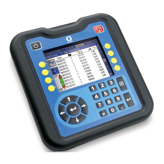
Troubleshooting Troubleshooting Error Codes When errors occur, press to acknowledge each error. After being acknowledged, the error will clear automati- cally when the condition that caused it is corrected. Active errors scroll on the menu bar. Alarms shut down the pattern controller and activate the dry contact PLC output. Advisories and deviation are infor- mational only and do not shut the system down. -
Page 46: Display
Troubleshooting Display Problem Cause Solution Display does not turn on Select dial on pattern control board set Integrated systems: set to 0 to wrong position Stand-alone systems: set 1 Power not turned on Check for green light on pattern control board and display Communication cable disconnected Verify pattern control board is connected to... -
Page 47: Valve
Troubleshooting Valve Problem Cause Solution System reset when guns Current draw from combined valves Ensure current draw is below 6A total between all fire exceeds power supply rating (150 W) simultaneously firing valves No glue dispensed Solenoid shorted Ensure proper wiring between solenoid and pat- tern controller. -
Page 48: Run Up
Troubleshooting Run Up Problem Cause Solution Run up controller reads 0 Integrated systems: InvisiPac systems Integrated systems: Turn system ON, run up is INACTIVE will be active once system is ACTIVE (pump will turn on) Stand-alone systems: PC system is INACTIVE Stand-alone systems: Turn system ON, run up controller will be active immediately... -
Page 49: Software Update Procedure
Software Update Procedure Software Update Procedure When software is updated on the ADM the software is First: then automatically updated on all connected GCA com- ponents. A status screen is shown while software is Software is check- updating to indicate progress. ing which GCA mod- ules will take the 1. -
Page 50: Usb Download
ADM. When will overwrite the oldest data. downloading from multiple ADMs, there will be one sub-folder in the GRACO folder for each ADM. NOTE: To prevent losing any data, never go more than 27 days without downloading the logs. -
Page 51: Parts
Parts Parts External Models 334784G... - Page 52 Parts Parts List Ref. Part Description Qty. Ref. Part Description Qty. 116772 CONNECTOR, plug, 3.81 - - - - - ENCLOSURE, PC, painted mm, 4 position - - - - - FOAM, gasket 119162 CONNECTOR, plug, 6 posi- - - - - - LABEL, pattern controller tion 4...
-
Page 53: Internal Models (Hm25C)
Internal Models (HM25c) Internal Models (HM25c) Parts List Ref. Part Description Qty. 17E019 MODULE, GCA, pattern control 17M504 HARNESS, PC-8 internal FRAME, cord grip, 4-position 125856 SCREW, 8-32, serrated flange 121000 CABLE, can female/female 0.5m 128117 CONNECTOR, plug, 3.81mm, 12-position 128147 CONNECTOR, plug, 3.81mm, 8-position 129538... -
Page 54: Internal Models (Hm25 And Hm50)
Internal Models (HM25c) Internal Models (HM25 and HM50) Parts List Ref. Part Description Qty. Ref. Part Description Qty. 116772 CONNECTOR, plug, 3.81 mm, 4 24X521 MODULE, GCA, PC-8e, internal position 101b 128176 FRAME, cable grip, 5 position 119162 CONNECTOR, plug, 3.81 mm, 6 101c 128177 INSERT, rubber, cable grip 4 x 6 position 132+ 128147 CONNECTOR, plug, 3.81 mm, 8... -
Page 55: Kits
Internal Models (HM25c) Kits Sensors/Mounting Part Description Contents Image 24X446 KIT, photoeye, diffuse, 128073 - SENSOR, photoelectric diffuse 18 mm 128071 - BRACKET, sensor mount, straight 128070 - BRACKET, sensor mount, angled 24X449 - CABLE, M12, 4-pin, 5.0 m 24X447 KIT, photoeye, pol ret ref, 128072 - SENSOR, photoelectric, polarized 18 mm 128071 - BRACKET, sensor mount, straight... - Page 56 Internal Models (HM25c) Cables Part Description Use with Image 24X449 KIT, cable, M12, 4-pin, Triggers with M12 connection (12 mm nut) F-L, 5 m Run-up controller 24X453 KIT, cable, M12, 4-pin, F-L, 10 m 24X454 KIT, cable, M12, 8-pin, Encoder F-L, 5 m 24X455 KIT, cable, M12,8-pin, F-L,...
- Page 57 Internal Models (HM25c) Upgrades Part Description Use with Image 24R324 KIT, software TOKEN, GCA, upgrade 17F712 KIT, PC-8 to PC-8e KIT, token, GCA, key, PC-8e upgrade CONNECTOR, plug, 3.81 mm, 7 position (x2) CONNECTOR, plug, 3.81 mm, 8 position (x2) 24Y171 KIT install, internal pat- HARNESS, secondary power and fuse tern control...
-
Page 58: Wiring Diagrams
Wiring Diagrams Wiring Diagrams NOTE: Refer to manual 3A4938 for HM25c internal pattern controller wiring. Internal Pattern Controller (HM25 and HM50 Systems with AWB) Ref. Part Description Qty. 128180 POWER SUPPLY, 120 W 128183 HARNESS, power, PC-8, 128182 CABLE communication 334784G... -
Page 59: Rail)
Wiring Diagrams Internal Pattern Controller (HM25 Systems with DIN Rail) Ref. Part Description Qty. 128180 POWER SUPPLY, 120 W 128265 HARNESS, power, PC-8, DIN 1 - - - - - HARNESS, fuse, PC-8, DIN 128807 CONNECTOR, splitter 128182 CABLE communication 125789 CABLE, communication 127068... -
Page 60: External Models
Wiring Diagrams External Models Ref. Part Description Qty. 15U423 SWITCH, 2P, 25 A 127887 POWER SUPPLY, 24 VDC, 6.3 A, 150 W - - - - - HARNESS, ground - - - - - CONNECTOR, plug, 3 position 1 - - - - - TERMINAL, fork, #8 - - - - - TERMINAL, fork, #4... -
Page 61: Dimensioned Drawings
Dimensioned Drawings Dimensioned Drawings System Enclosure 3.33 in 10.01 in (84.5 mm) (254.25 mm) .87 in (22 mm) 10.28 in (261 mm) 1.5 in .63 in (38.1 mm) (16 mm) ti31573a Triggers 128071 - Mounting Bracket, Straight 128072 - Polarized Retro-Reflective Sensor 128073 - Diffuse Sensor 16.2 in (411.4 mm) - Page 62 Dimensioned Drawings Encoders 128074 - Encoder, Incremental 17E018 - Universal Bracket .393 in 12.5 in 3X M4 (10 mm) (317.5 mm) 8X .313 in 10.69 in .748 in (271.52 mm) (7.95 mm) (19 mm) 2.362 in 1.45 in 2.05 in 2.75 in (36.83 mm) (60 mm)
- Page 63 Dimensioned Drawings Couplers Part Graco Encoder Customer Shaft Shaft (Bore) 17F540 6 mm 17F541 8 mm 17F542 10 mm 17F543 12 mm 1 in. 0.374 in. 0.25 in. 0.984 in. 17F544 1/8 in. (25.4 mm) (9.5 mm) (6.4 mm) (25.0 mm) 17F545 3/16 in.
-
Page 64: Technical Specifications
Technical Specifications Technical Specifications InvisiPac Pattern Controller Description Value Details Input Power External models only 100-240 VAC, 50/60 Hz, 2A max Gun Outputs 24 VDC, 1A each, 6A max total Total Gun 120 W (internal models - HM25c) Wattage 90 W (internal models - HM25 and HM50) - - - - - 150 W (external models) Trigger Inputs... -
Page 65: Notes
Notes... -
Page 66: Graco Standard Warranty
With the exception of any special, extended, or limited warranty published by Graco, Graco will, for a period of twelve months from the date of sale, repair or replace any part of the equipment determined by Graco to be defective.