Advertisement
Quick Links
Instructions-Parts
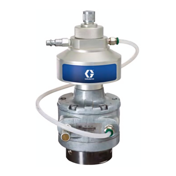
24G621 Agitator Speed Controller
Accessory
Accessory kit to control and automatically maintain the speed of an air-powered agitator.
For professional use only.
Important Safety Instructions
Read all warnings and instructions in this manual
and in your separate agitator manual. Save these instructions.
Patent Pending
PROVEN QUALITY. LEADING TECHNOLOGY.
3A1315A
ENG
TI17253a
Advertisement

Related Manuals for Graco 24G621


Summary of Contents for Graco 24G621
- Page 1 Instructions-Parts 24G621 Agitator Speed Controller 3A1315A Accessory Accessory kit to control and automatically maintain the speed of an air-powered agitator. For professional use only. Important Safety Instructions Read all warnings and instructions in this manual and in your separate agitator manual. Save these instructions.
-
Page 2: Table Of Contents
Contents Kit Parts ............. 8 Installation............3 Operation ............5 Technical Data ........... 10 Troubleshooting..........6 Notes ............... 11 Repair..............7 Graco Standard Warranty........12 3A1315A... -
Page 3: Installation
Installation 2. Install the push-to-connect air tube connector (21) in place of the needle valve. The agitator speed controller fits the following Graco pneumatic rotary motors: Motor Part No. 101140 16A871 101388 111310 NOTE: Before installing, ensure that the agitator air motor has at least 5 in. - Page 4 4. Using the allen wrench (25) and multi-function 6. Connect the air tubing (27) between the speed wrench (26), tighten the compression nut (24) controller tube connector (29) and the air motor onto the flange connector at least 1/8 turn past tube connector (21).
-
Page 5: Operation
Operation Connect the main air line to the quick disconnect fitting (28) on the agitator speed controller. Do not exceed the maximum air inlet pressure of 100 psi (0.7 MPa, 7.0 bar). Turn knob counterclockwise Set the agitator speed using the knob (16) on Turn knob clockwise to increase speed. -
Page 6: Troubleshooting
Troubleshooting Problem Solution The speed controller does not adjust for a change in Remove the needle (13). and liberally lubricate the load, or shuts off before the knob (16) is turned all needle and o-ring (33) with multi-purpose lithium the way down. based grease. -
Page 7: Repair
Repair (12). Install the drive shaft (4) and cam arm assembly into the lower housing (1), making sure the bearing (3*) seats fully in the recess of the NOTE: To repair the agitator, see your separate housing. agitator manual. 10. Screw the upper housing (2) fully onto the lower NOTE: Repair Kit 24J886 is available. -
Page 8: Kit Parts
Kit Parts Ref. Description The kit contains all necessary parts and tools to TUBE, nylon; 1/4 in. (6 mm) OD; 2 install the agitator speed controller. ft (0.6 m) Ref. Description FITTING, quick-disconnect, air; 1/8 npt(m) HOUSING, lower, speed controller CONNECTOR;... - Page 9 ti17005a 3A1315A...
-
Page 10: Technical Data
Technical Data Maximum air supply pressure 100 psi (0.7 MPa, 7 bar) Minimum air supply pressure 70 psi (0.5 MPa, 4.9 bar) Maximum speed 1000 rpm Maximum speed controller air temperature 130°F (55°C) Main air inlet size 1/8 npt quick-disconnect fitting Speed control range 100–1000 rpm Diameter... -
Page 11: Notes
Notes 3A1315A... -
Page 12: Graco Standard Warranty
Graco to be defective. This warranty applies only when the equipment is installed, operated and maintained in accordance with Graco’s written recommendations. This warranty does not cover, and Graco shall not be liable for general wear and tear, or any malfunction, damage or wear caused by faulty installation, misapplication, abrasion, corrosion, inadequate or improper maintenance, negligence, accident, tampering, or substitution of non-Graco component parts.