Table of Contents
Advertisement
Quick Links
Instructions
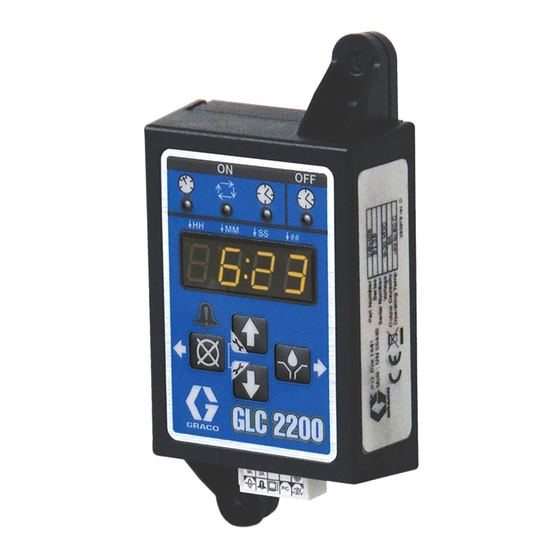
GLC 2200
Lubrication Controller
For controlling and monitoring an automated lubrication system.
Not approved for use in explosive atmospheres or hazardous locations.
Model: 24N468
Important Safety Instructions
Read all warnings and instructions in this
manual. Save these instructions.
3A2960A
EN
Advertisement
Table of Contents

Related Manuals for Graco GLC 2200


Summary of Contents for Graco GLC 2200
- Page 1 Instructions GLC 2200 Lubrication Controller 3A2960A For controlling and monitoring an automated lubrication system. Not approved for use in explosive atmospheres or hazardous locations. Model: 24N468 Important Safety Instructions Read all warnings and instructions in this manual. Save these instructions.
- Page 2 Warnings Warnings The following warnings are for the setup, use, grounding, maintenance, and repair of this equipment. The exclama- tion point symbol alerts you to a general warning and the hazard symbols refer to Procedure-specific risks. When these symbols appear in the body of this manual or on warning labels, refer back to these Warnings. Product-specific hazard symbols and warnings not covered in this section may appear throughout the body of this manual where applicable.
-
Page 3: Component Identification
Component Identification Component Identification Keypad, Display, and Icons Display (E) NOTICE • A blinking field on the display indicates the controller To prevent damage to soft key buttons, do not press is in SETUP MODE. the buttons with sharp objects such as pens, plastic cards, or fingernails. -
Page 4: Typical Installation
Installation Installation Typical Installation The installation shown in F . 2 is only a guide for selecting and installing system components. Contact your Graco distributor for assistance in planning a system to suit your needs. Controller Capabilities Low Reservoir Level... - Page 5 Installation Installing the Lubrication Controller AUTOMATIC SYSTEM ACTIVATION HAZARD Unexpected activation of the system could result in seri- ous injury, including skin injection and amputation. This device has an automatic timer that activates the pump lubrication system when power is connected or when exiting the programming function.
-
Page 6: System Configuration And Wiring
Installation System Configuration and Wiring The System Configuration Diagrams (F . 4 - F . 6), Sensor Wiring Diagrams (F . 7 - F . 8) and Wiring Diagrams . 9) on the following pages, show typical Injector, Series Progressive and Dual Line lubrication system configura- tions. -
Page 7: System Configuration
Installation System Configuration Injector System Lubrication Points Injectors Pressure Switch Vent Line Pump Reservoir Low Level Switch Pump On/Off GLC 2200 External Alarm 3A2960A... - Page 8 Installation Series Progressive System Master Divider Valve Cycle Switch Pump Secondary Divider Valves Reservoir Low Level Switch GLC 2200 Pump On/Off External Alarm 3A2960A...
- Page 9 Installation Dual Line System Lubrication Points Cycle Switch Reverser Bi-flo Valves Vent Line Pump Reservoir Low Level Switch GLC 2200 Pump On/Off External Alarm 3A2960A...
- Page 10 Installation Sensor Wiring Configurations DRY CONTACT SWITCH SOURCE SWITCH - 2 or 3 Wire Type +VDC 3A2960A...
-
Page 11: Wiring Diagram
Installation Wiring Diagram Modes of Operation: Optional I/O Wiring Diagram Used with all modes of GLC2200 Operation 9A Fuse Wiring Key Connector Identification Label Description Pump Alarm P/C +9V Low Level +30V Pressure Cycle Switch Voltage Input Pump Alarm Low Level Pressure Cycle Switch Voltage Input 3A2960A... - Page 12 Setup Setup Entering SETUP MODE Cycle Mode (on:CY) ON Setup 1. Use the UP or DOWN ARROW to 1. Press both the UP and DOWN ARROW buttons cycle through the on:Pr, on:CY or together for three seconds. on:ti on the display. NOTE: If a button is not pushed for 1 minute, the control- ler returns to the start of an OFF cycle.
- Page 13 Setup 2. When on:ti is displayed, press Programming OFF TIME Duration ENTER to lock in the selection. After setting the parameters for either Pressure (P), Cycle (C) or Time (T) ON Modes, the OFF or PUMP REST CYCLE must be set up. 3.
-
Page 14: Operation
Setup Programming the Low Level (LL:dF) Setting • Pump ON time is shown in MM:SS (minutes:sec- onds) LL:dF displays. This is the basic configuration and requires one activation. Pressure Mode: Pump OFF 1. Use the UP or DOWN ARROW to The display indicates the amount of time remaining in cycle through until LL:93 displays. -
Page 15: Alarm Operation
Setup • Pump OFF time is shown in HH:MM (hours:minutes) or MM:SS if the time remaining is less than an hour. Timer Mode: Pump ON The display indicates the amount of time remaining in the pump cycle, counting down the Pump ON time value (see Time Control (on:ti) ON Setup, page 12). -
Page 16: Technical Data
Technical Data Technical Data Input Contact Power Source DC 9 - 30 VDC Cycle Pressure Control Input (optional) Normally open Pressure or cycle switch Lubrication level (optional) Normally open level switch, closes upon low level Outputs Pump control Pump Control Voltage = Power Source Voltage Power Source Max Switching Voltage... -
Page 17: Mounting Hole Layout
Dimensions Dimensions Mounting Hole Layout 4.95 in. (125.8 mm) 2.75 in. (69.85 mm) 1.23 in. 1.63 in. (31.24 mm) (41.4 mm) 5.5 in. (139.7 mm) 3A2960A... -
Page 18: Graco Standard Warranty
With the exception of any special, extended, or limited warranty published by Graco, Graco will, for a period of twelve months from the date of sale, repair or replace any part of the equipment determined by Graco to be defective.