Advertisement
Table of Contents
Instructions
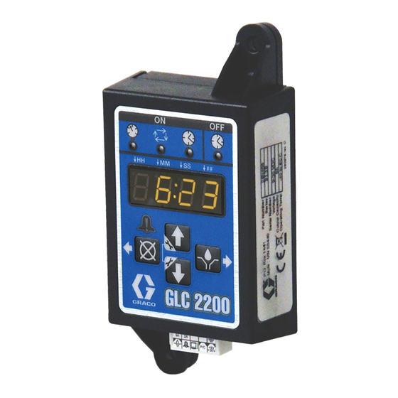
GLC 2200
Lubrication Controller
For controlling and monitoring an automated lubrication system.
Not approved for outdoor use or use in explosive atmospheres or hazardous locations.
Model: 24N468
Important Safety Instructions
Read all warnings and instructions in this
manual. Save these instructions.
3A2960F
EN
Advertisement
Table of Contents

Related Manuals for Graco GLC 2200


Summary of Contents for Graco GLC 2200
- Page 1 Instructions GLC 2200 Lubrication Controller 3A2960F For controlling and monitoring an automated lubrication system. Not approved for outdoor use or use in explosive atmospheres or hazardous locations. Model: 24N468 Important Safety Instructions Read all warnings and instructions in this manual. Save these instructions.
- Page 2 Warnings Warnings The following warnings are for the setup, use, grounding, maintenance, and repair of this equipment. The exclama- tion point symbol alerts you to a general warning and the hazard symbols refer to Procedure-specific risks. When these symbols appear in the body of this manual or on warning labels, refer back to these Warnings. Product-specific hazard symbols and warnings not covered in this section may appear throughout the body of this manual where applicable.
-
Page 3: Component Identification
Component Identification Component Identification Keypad, Display, and Icons Display (E) NOTICE •A blinking field on the display indicates the controller is To prevent damage to soft key buttons, do not press in SETUP MODE. the buttons with sharp objects such as pens, plastic cards, or fingernails. -
Page 4: Typical Installation
Installation Installation Typical Installation The installation shown in F . 2 is only a guide for selecting and installing system components. Contact your Graco distributor for assistance in planning a system to suit your needs. Controller Capabilities Low Reservoir Level... -
Page 5: System Configuration And Wiring
Installation Installing the Lubrication System Configuration and Controller Wiring The System Configuration Diagrams (F . 4 - F . 6), Sensor Wiring Diagrams (F . 8 - F . 9) and Wiring Dia- grams (F . 7) on the following pages, show typical Injector, Series Progressive and Dual Line lubrication AUTOMATIC SYSTEM ACTIVATION HAZARD system configurations. -
Page 6: System Configuration
Installation System Configuration Injector System Lubrication Points Injectors Pressure Switch Vent Valve Vent Line Pump & Reservoir Low Level Switch Pump On/Off GLC 2200 External Alarm 3A2960F... - Page 7 Installation Divider Valve System Master Divider Valve Cycle Switch Pump & Secondary Divider Valves Reservoir Low Level Switch GLC 2200 Pump On/Off External Alarm 3A2960F...
- Page 8 Installation Dual Line System Lubrication Points Cycle Switch Reverser Bi-flo Valves Vent Line Pump & Reservoir Low Level Switch GLC 2200 Pump On/Off External Alarm 3A2960F...
-
Page 9: Wiring Diagram
Installation Wiring Diagram Modes of Operation: Optional I/O Wiring Diagram Used with all modes of GLC2200 Operation 9A Fuse *Normally open vent valve for use with Injector-based systems Wiring Key Connector Identification Label Description Pump Alarm P/C +9V Low Level +30V Pressure/Cycle Switch Voltage Input... - Page 10 Installation Sensor Wiring Configurations DRY CONTACT SWITCH GLC 2200 SOURCE SWITCH - 2 or 3 Wire Type +VDC GLC 2200 -VDC 3A2960F...
- Page 11 Setup Setup Entering SETUP MODE To enter the PIN Code: 1.Press both the UP and DOWN ARROW 1.Press both the UP and DOWN ARROW buttons buttons for 3 seconds. together for three seconds. NOTE: •If a button is not pushed for 1 minute, the controller returns to the start of an OFF cycle.
- Page 12 Setup Programming ON Duration Cycle Control (on:CY) ON Setup 1.Use the UP or DOWN ARROW until •on:Pr, on:CY or on:ti appears on the display identify- on:CY displays. ing the function you are programming (see below). •The illuminated LED below the related symbol on the controller label also indicates the function.
- Page 13 0-5 until the desired number appears in the first Minutes (MM) field. To determine the Backup Time, Graco recommends the NOTE: user verify the length of time it takes to complete a typi- cal cycle and double that value.
- Page 14 Setup 4.Press the ENTER button. The next number field to the right flashes indicating it is ready to program the Minutes (MM) fields. The next number field to the right flashes and the LED lights under SS; NOTE: indicating it is ready to program the seconds fields. •The MM field is a 2-digit number.
- Page 15 This setting is intended for use with a persistent output. “paddle-style” low level sensors (such as the Graco G3 grease units).The The enters a low level condition after the switch input is pump stops when low level occurs. To ensure a low level...
-
Page 16: Operation
Operation Operation Run Mode Cycle Mode: Pump ON The display alternates between the number of cycles The controller is in Run Mode providing the following cir- remaining and indicates the amount of time remaining in cumstances are present: the pump cycle, counting down the Backup Pump ON time value (see Cycle Mode (on:CY) ON Setup, page •The controller is not in SETUP MODE. -
Page 17: Alarm Operation
Operation Timer Mode: Pump OFF The display indicates the amount of time remaining in the pump OFF cycle, counting down the Pump OFF time value (see Programming OFF Time Duration, page 13). •The Time OFF LED illuminates and the pump output is disabled during the Pump OFF time. - Page 18 Operation Alarm Types and Messages Alarm Type Error Code Description Things to Check/Do Refill lubrication reservoir. Low Level Low lubricant level If low level fault occurs unexpectedly verify wiring and programming setup. Inspect lubrication system for broken or plugged lines. Confirm pump is operating correctly.
- Page 19 PIN Code. Use the UP A1 - Setting Up PIN Code and DOWN ARROW buttons to move A PIN Code can be programmed into the GLC 2200 to through the numbers 0-9 until the first protect the settings from inadvertently being changed by number in the PIN code is displayed.
- Page 20 Advanced Programming (Series E or later models only) 1.The word A1:OF appears in the display. 1.The word A3:ON appears in the display. Press the UP or DOWN ARROW button Press the UP or DOWN ARROW button to change this to A1:ON. to cycle between A3:ON and A3:OF.
-
Page 21: Troubleshooting
Troubleshooting Troubleshooting Description Problem Solution Refer to installation instructions Incorrect or loose wiring beginning on page 4. Input voltage is out of range Confirm power source is between 9 Unit does not power on or display is and 30 VDC. dim/unresponsive Tripped external fuse Confirm that none of the devices or... - Page 22 Parts Parts Ref. Description BOX, enclosure LABEL, control, overlay LABEL, serial, name LABEL, connector Accessories Related Kits Kit No. Description 24P314 GLC2200 Wiring Harness Kit 24P686 Single Connector Kit 24P687 Multiple Connector Kit 3A2960F...
-
Page 23: Technical Data
Technical Data Technical Data Input Contact Power Source DC 9 - 30 VDC Power Consumption 1 Watt Cycle/Pressure Control Input (optional) 9 - 30 VDC, Normally open Pressure or cycle switch Lubrication level (optional) Normally open level switch, closes upon low level Outputs Pump control Pump Control Voltage = Power Source... -
Page 24: Mounting Hole Layout
Dimensions Dimensions Mounting Hole Layout Ø 0.2 in. (5.0 mm)- 4.92 in. (125.0 mm) 2.75 in. (70.0 mm) 1.38 in. (35.0 mm) 1.57 in. (40.0 mm) 5.53 in. (140.0 mm) 3A2960F... - Page 25 Notes Notes 3A2960F...
-
Page 26: Graco Standard Warranty
With the exception of any special, extended, or limited warranty published by Graco, Graco will, for a period of twelve months from the date of sale, repair or replace any part of the equipment determined by Graco to be defective.