Table of Contents
Advertisement
Setup and Operation
HV-2000C Jet
Controller
Diaphragm-Jet
For controlling non-contact dispensing of viscous material in industrial
environments. For Professional Use only.
Important Safety Instructions
Read all warnings and instructions in this manual
and all related manuals before using this
equipment. Save these instructions.
™
Technology
PROVEN QUALITY. LEADING TECHNOLOGY.
3A5856A
EN
Advertisement
Table of Contents

Related Manuals for Graco Advanjet Diaphragm-Jet HV-2000


Summary of Contents for Graco Advanjet Diaphragm-Jet HV-2000
- Page 1 Setup and Operation HV-2000C Jet Controller 3A5856A ™ Diaphragm-Jet Technology For controlling non-contact dispensing of viscous material in industrial environments. For Professional Use only. Important Safety Instructions Read all warnings and instructions in this manual and all related manuals before using this equipment.
-
Page 2: Table Of Contents
Table of Contents RELATED MANUALS ....................4 SAFETY GUIDELINES ....................5 INTRODUCTION AND SPECIFICATIONS ............6 1.1 Advanjet HV-2000/2000C Overview ............6 1.2 HV-2000C Controller Specifications ............. 7 1.3 Technical Assistance ................... 7 1.4 HV-2000C Controller Dimensions ..............8 1.5 HV-2000C Front and Rear Features ............9 INSTALLATION AND SETUP ................ - Page 3 Schematic for D/A Converter Outputs ........57 Appendix 4-5: Schematic for Pressure Alarm Input/Output Circuit ....58 APPENDIX 5: REPLACING THE 24V DRIVER BOARD FUSE ........ 59 GRACO STANDARD WARRANTY ................60 3A5856A Advanjet HV-2000C Jet Controller Setup and Operation Page 3 of 60...
-
Page 4: Related Manuals
Related Manuals Manuals are available at www.graco.com. Component manuals below are in English: 3A5855 HV-2000 Jet Setup and Operation 3A5908 Advanjet Jet Maintenance Tool Kit (JKT-2000) 3A5909 HV-2000 Maintenance and Repair Page 4 of 60 Advanjet HV-2000C Jet Controller Setup and Operation... -
Page 5: Safety Guidelines
Safety Guidelines Hazards may arise if handled improperly by unqualified personnel. It is recommended that operating personnel thoroughly review these operating instructions. The following warnings are for the setup, use, grounding, maintenance, and repair of this equipment. The exclamation point symbol alerts you to a general warning and the hazard symbols refer to procedure-specific risks. -
Page 6: Introduction And Specifications
1. Introduction and Specifications Advanjet HV-2000/2000C Overview Advanjet HV-2000 non-contact jetting technology is a major leap in liquid dispensing. The non-contact jetting is fast, allowing dispensing rates up to 300Hz. The user can modify the drop size 20% from its nominal size, allowing a wide range of adjustability. ±... -
Page 7: Hv-2000C Controller Specifications
HV-2000C Controller Specifications PARAMETER SPECIFICATION Size Width: 254.0 mm (10.00 in) Height: 152.5 mm (6.00 in) Depth: 341.4 mm (13.44 in) Weight: 3200 g (7.05 lbs) Drop Parameters Refill time and Dwell (0.1 msec resolution) Number of drops (programmable from 1 to 1M) Recipes 6 independent recipes, manual or remote triggers Heating to 70 C Max... -
Page 8: Hv-2000C Controller Dimensions
HV-2000C Controller Dimensions Note: Units are in millimeters [inches] Page 8 of 60 Advanjet HV-2000C Jet Controller Setup and Operation 3A5856A... -
Page 9: Hv-2000C Front And Rear Features
HV-2000C Front and Rear Features TRIGGER LED LCD DISPLAY KEYPAD ILLUMINATES WHEN SHOWS PROGRAM MOVES LCD DISPLAY CURSOR, PARAMETERS DISPENSING CHANGES PARAMETER VALUES POWER SWITCH TRIGGER BUTTON TURNS THE EXECUTES THE HV-2000C DISPENSING RECIPE MAIN POWER ON LCD DISPLAY ON/OFF (ONCE) FLUID PRESSURE GAUGE... -
Page 10: Installation And Setup
2. Installation and Setup Physical Placement The HV-2000C controller should be placed in a location where the front panel controls can be viewed and accessed. The ventilation holes on the sides should not be blocked. Pneumatic System NOTICE It is imperative that the air supplied to the HV-2000 is clean and dry and free from debris and water. -
Page 11: Electrical Interface
Electrical Interface JET CABLE RS-232C CABLE I/O CABLE POWER CORD Figure 2-2: HV-2000C Cable Connections Four cable connections are on the rear of the Advanjet controller: Power cord, RS-232, Jet, and Digital I/O, as shown in Figure 2-2. To assure proper connections to the Advanjet controller, each of the standard cables supplied by Advanjet has a distinct connector. -
Page 12: Input / Output Connections
Input / Output Connections A standard, 5-foot 26-pin Input/Output cable is supplied with the HV-2000C. The table below describes the I/O connector pin assignments. The I/O is configured for the inputs to be pulled down to GND. When the specific input is triggered, the Advanjet controller will activate the corresponding preprogrammed Recipe # shown. -
Page 13: Using The Hv-2000C Controller Front Panel
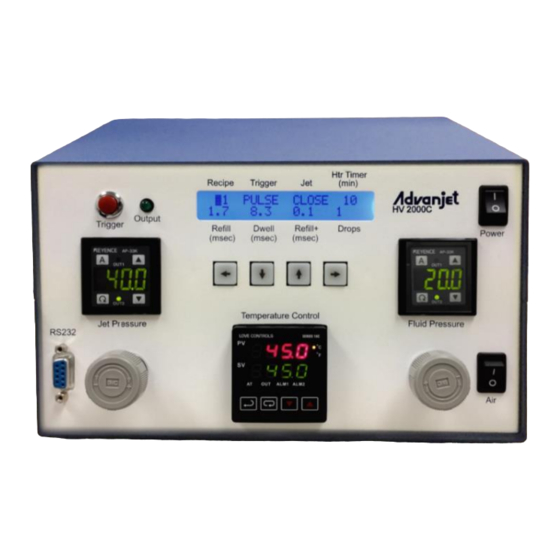
3. Using the HV-2000C Controller Front Panel TRIGGER LED KEYPAD LCD DISPLAY POWER TRIGGER SWITCH BUTTON FLUID PRESSURE PRESSURE GAUGE GAUGE RS-232 PORT SWITCH JET PRESSURE TEMPERATURE FLUID PRESSURE CONTROLLER CONTROLLER CONTROLLER Figure 3-1: HV-2000C Front Panel Jet and Fluid Pressure Regulators The HV-2000C controller has two integrated air regulators (see Figure 3-2) that control the pressure to the Jet and the Fluid supply. -
Page 14: Temperature Controller
Temperature Controller The HV-2000C Temperature Controller regulates the temperature of the dispensing fluid and displays the present and set point temperatures. The main menu displays the present temperature value (PV) in red on the top line of the display and the Figure 3-5: set point temperature value (SV) in green on the Temperature Controller... -
Page 15: Trigger Button And Led
Temperature Controller (Continued) To turn OFF the heater: Press until the Run-Stop screen is displayed (r-S). Use the keys to Figure 3-8: Turn OFF the Heater select the Stop setting to turn OFF the heater. Press the key to save the change. -
Page 16: Lcd Display And Selection Keys
LCD Display and Selection Keys HV-2000C front panel programming and operation uses the LCD display and input keypad, highlighted in Figure 3-11 at right. Eight basic settings can be input from the main LCD menu. The selected setting is indicated by a blinking cursor. - Page 17 Jet Setting from the Front Panel (Continued) Refill (msec): Refill time is the time required for the material to flow into the nozzle after each drop is ejected. Refill is set in msec with 0.1 msec resolution. Section 6.1 - Timing Recipe Parameters provides a detailed explanation of Refill Time.
-
Page 18: Special Front Panel Key Sequences
Special Front Panel Key Sequences Pressing a combination of front panel keys accesses additional settings. Refill++ time: Simultaneously pressing the LEFT and RIGHT keys once brings up the Refill++ time menu. As another method of first drop compensation, Refill++ time is added to Refill time after the jet is idled for a defined number of seconds. -
Page 19: Rs-232 Communication
4. RS-232 Communication RS-232 Connector Pins On some HV-2000C models there is a serial port DB9P female connector located on the front panel. This RS-232 port is used to connect the controller to a PC using a USB-to-Serial Adapter cable. Connect the USB Plug end to the PC’s USB port, and connect the Serial DB9 plug to the RS-232 port. -
Page 20: Changing The Default Rs-232 Settings
Changing the Default RS-232 Settings The default settings for the RS-232 data interface are CTS ON, Baud Rate 57600, Parity NONE, and Data Length 8BIT. To change the default RS-232 settings, simultaneously press the LEFT and RIGHT keys twice. (Pressing L+R one time displays the Refill++ settings;... -
Page 21: Advanjet Software
5. Advanjet Software The Advanjet software is not required if the controller will always be operated from the front panel keys. However, if a PC user interface is preferred, or if access to the controller front panel keys is limited, the Advanjet Software provides the option of programming the jetting parameters from a PC using Windows XP, Vista, Windows 7, and Windows 8. -
Page 22: Settings Menu
Settings Menu This section describes features 1 – 11 of the Advanjet Software Settings Menu as shown in Figure 5-1 on the previous page. Valve Status: Turn the Jet valve ON or OFF by clicking on the large indicator button (RED = ON, BLUE = OFF). The Jet valve is ON by default at startup. When the button is RED, the Jet valve is activated and it will block the fluid flow. - Page 23 Settings Menu (Continued) Trigger Map: Displays the assignment of the trigger input to the dispensing recipes. For example, in Figure 5-2 below, input trigger signal from I/O Pin 1 is used to activate Recipe #1. The BusyFlag (I/O Pin 7) is an output signal that the external controller/robot can use to monitor the Jet status.
- Page 24 Settings Menu (Continued) RS-232 Settings: The default settings for the Advanjet program and the controller are as follows: SETTING DEFAULT OPTIONS CTS (hardware handshake) ON or OFF Baud Rate 57600 57600, 19200, 9600 or 4800 Parity NONE NONE, EVEN or ODD Data Length 8BIT 8BIT or 7BIT...
-
Page 25: Running A Program From Software
Running a Program from Software Before running a program for the first time, make sure to check the following: Connect all electrical cables to the HV-2000. This includes the jet cable, the I/O cable if remote triggering is used, the RS-232 cable when running from the computer, and the power cable. -
Page 26: Timing Recipes
6. Timing Recipes Before dispensing can begin, Timing Recipes must be created for the particular fluids being dispensed. Figure 6-1 on the next page shows the Timing Recipes Menu of the Advanjet software. Once configured, the Timing Recipes can be downloaded into the Advanjet controller. -
Page 27: Programming Timing Recipes
Programming Timing Recipes TIMING RECIPES LIST (1 – 12) REFILL TIME DWELL TIME REFILL+ TIME (FOR FIRST DROP) Figure 6-1: Timing Recipes Main Menu The Advanjet software offers several sample Timing Recipes for popular fluids for a quick start-up. As shown in Figure 6-1 above, the Timing Recipes main menu screen lists the dispensing parameters on the HV-2000C controller front panel. - Page 28 Programming Timing Recipes (Continued) Refill Time: Sets the time required for the material to flow into the orifice after each drop has been ejected. Time is set in msec with 0.1 msec resolution. Reserved 2 to Reserved 5: These timers are not used for the HV-2000. They are set to zero by default.
-
Page 29: Drop Mode Programming
DROP Mode Programming Programming the Advanjet system is very simple and flexible, as shown in the following examples. Dispensing one drop at a time On the Settings Menu (see Section 5.2), select the pull-down menu to set the timing recipe for ―Recipe #1‖ Set the Count entry to 1 for ―Recipe #1‖... -
Page 30: Line Mode Programming
LINE Mode Programming The Advanjet software and HV-2000C controller make dispensing lines very simple. The following examples illustrate how this is done. Method 1: Jetting a line in PULSE mode Click on the Timing Recipes tab, select a Recipe # and enter a Refill time of 2 msec and Dwell time of 3 msec. -
Page 31: Method 3: Jetting A Line During An X-Y Move
LINE Mode Programming (Continued) Method 3: Jetting a line during an X-Y move There is another method to dispense a line if the Robot has the capability to issue triggers during an X-Y move. The Robot will make an X-Y move and send pulses of trigger to the controller at the position where it wants to jet a drop. -
Page 32: Advanjet Controller Commands (Acc)
7. Advanjet Controller Commands (ACC) The ACC is a simple set of commands for controlling the Jet, timing values, and settings for the recipes. A host computer or external robot is connected to the Advanjet controller via an RS-232 cable. The host/robot sends ACC to the controller in ASCII format. This section serves as a reference for using ACC to write a custom program for the Advanjet Controller. -
Page 33: Recipe Timing Commands
Recipe Timing Commands Set Recipe Timers #RecipeID,#Refill,#0,#0,#0,#0,#Dwell; The ST function configures the timing values for the recipe. #RecipeID numbers 0 to 5 correspond to Recipes 1 to 6. #RecipeID 0 #RecipeID 1 #RecipeID 2 #RecipeID 3 ... - Page 34 Recipe Timing Commands (Continued) Adjust Refill Time for First Drop #nRecipeID,#Refill+,#Refill++,#DelaySec; The SL command adjusts the Refill Time for the first dot. These values help to control the size and quality of the first dot. Four parameters are required for this function, defined as follows: # nRecipeID Identifies the recipe;...
-
Page 35: Jetting Commands
Jetting Commands Select Recipe # nRecipeID; The SM command identifies the recipe that the controller should use when it receives a SG (start dispensing) command from the host/robot. This command should be sent before an SG command to identify the recipe timers and settings. # nRecipeID Identifies the recipe;... - Page 36 Jetting Commands (Continued) Set Jet Value State # nValveID,# nValveStatus; This command allows the host to open or close the Jet valve. # nValveID Sets # nValveID to 0 for Jet valve # nValveStatus Sets # nValveStatus; 1 = open and 0 = closed Example: SV 0,1;...
-
Page 37: Heater Commands
Heater Commands Set Heater Temperature # nTemperature; The SH command allows the host to set the temperature for the Heater Controller in the Advanjet Controller. # nTemperature Sets temperature value in degrees Celsius. This value should be less than 75 degrees Celsius (167 °F). Turn Heater On/Off # nFlag;... -
Page 38: Output Commands
Output Commands Output Internal Drop Counter The host can send the OD; command to determine the number of drops that have been completed since the last SD; command (reset counter command). A return string consisting of the total number of drops will be returned. Output Error The host can send the OE;... -
Page 39: Appendix 1: First Drop Compensation
Appendix 1: First Drop Compensation Appendix 1-1: Background Many viscous fluids are thixotropic and their viscosity decreases with motion. This is often referred to as shear thinning. When dispensing a thixotropic fluid, the very first drop ejected is often smaller than subsequent drops if the jet has been idle for some time. -
Page 40: Appendix 1-3: First Drop Compensation In Pulse Mode
Appendix 1-3: First Drop Compensation in PULSE Mode In this mode, the controller produces ―n‖ drops when it receives a trigger signal, where ―n‖ is the number of drops. Refill Time for the first dot = Refill + T ... - Page 41 Appendix 1-3: First Drop Compensation in PULSE Mode (Continued) Example 2: Number of drops = 3 In the timing diagram below, T* = T Therefore, the first drop = Refill + T The refill time for all other drops = Refill (no first drop compensations added). ELAPSE TIME TRIGGER SIGNAL JET BUSY OUTPUT...
-
Page 42: Appendix 1-4: First Drop Compensation In Level Mode
Appendix 1-4: First Drop Compensation in LEVEL Mode In this mode, the controller produces drops as long as the Trigger signal is high Refill Time for the first dot = Refill + T Refill Time for all other dots = Refill TRIGGER SIGNAL JET BUSY OUTPUT DWELL... -
Page 43: Appendix 2: Temperature Controller Factory Settings
Appendix 2: Temperature Controller Factory Settings The CN740 Temperature Controller manual is included with your Advanjet controller shipment. Please refer to it for specific instructions. Listed below are factory set values programmed by Advanjet to work with the HV-2000C controller and the HV-2000 Jet Nozzle plate for the majority of applications. It is strongly recommended that users do not modify these values. - Page 44 Co5H Communication write-in selection C-no Controller Address 9600 Baud Rate Setting Communication Data Length Prty nonE Communication Parity Bit Stop Communication Stop Bit Page 44 of 60 Advanjet HV-2000C Jet Controller Setup and Operation 3A5856A...
-
Page 45: Appendix 3: Digital Pressure Gauge
Appendix 3: Digital Pressure Gauge Appendix 3-1: Specifications AP-30 Series Two-Color Digital Display Pressure Sensor NEGATIVE POSITIVE COMPOUND TYPE PRESSURE PRESSURE PRESSURE Model AP-31K (P) AP-32K (P) AP-33K (P) AP-34K Rated pressure 0 to -29.9 inHg 0 to 14.50 psi 0 to 145.0 psi 29.9 to -29.9 inHg (0 to -101.3 kPa) -
Page 46: Appendix 3-2: Part Names And Functions
Appendix 3-2: Part Names and Functions Page 46 of 60 Advanjet HV-2000C Jet Controller Setup and Operation 3A5856A... -
Page 47: Appendix 3-3: Connections And Input/Output Circuit
Appendix 3-3: Connections and Input/Output Circuit 3A5856A Advanjet HV-2000C Jet Controller Setup and Operation Page 47 of 60... -
Page 48: Appendix 3-4: Operation Mode Selection
Appendix 3-4: Operation Mode Selection Page 48 of 60 Advanjet HV-2000C Jet Controller Setup and Operation 3A5856A... -
Page 49: Appendix 3-5: Operation Mode Selection
Appendix 3-5: Operation Mode Selection 3A5856A Advanjet HV-2000C Jet Controller Setup and Operation Page 49 of 60... -
Page 50: Appendix 3-6: Adjustment
Appendix 3-6: Adjustment Page 50 of 60 Advanjet HV-2000C Jet Controller Setup and Operation 3A5856A... -
Page 51: Appendix 3-7: Other Functions And Error Indications
Appendix 3-7: Other Functions and Error Indications 3A5856A Advanjet HV-2000C Jet Controller Setup and Operation Page 51 of 60... -
Page 52: Appendix 4: Input/Output Connector
Appendix 4: Input/Output Connector The HD26 I/O connector connects to one type of input circuit and four types of output circuits. The design notes suggest at least one interface circuit on the user’s side of each type of input or output. As a general rule, a good interface should provide level shifting and galvanic isolation between the jet controller and the robot. - Page 53 Appendix 4-1: HD26 Pin Assignments (Continued) HD26 HV-2000C Pin Name, Terminology, Number Specifications Schematic Recipe 1 (Input) Configurable Bit 0, DIO 16. I/O DIO0- Digital input 0–5 V DC, switching threshold 1.4 V/1.9 V typical. DIO31 Input is normally high. Assert by pulling low. Recipe 2 (Input) Configurable Bit 1, DIO 17.
- Page 54 Appendix 4-1: HD26 Pin Assignments (Continued) Analog input AIN 5 Buffered A/D 11-bit res. channel, software-selectable ranges Converter Inputs unipolar: 1, 2, 2.5, 5, 10, 20 V DC; bipolar ± 1, ±2, ±5, ±10 V DC; 4 channels can be hardware-configured for 4–20 mA; 1 MÙ...
-
Page 55: Appendix 4-2: Schematic For Configurable I/O Dio0-Dio31
Appendix 4-2: Schematic for Configurable I/O DIO0-DIO31 I/O configured for 5 VDC Main Control Board Schematic 1: Configurable I/O DIO0-DIO31 3A5856A Advanjet HV-2000C Jet Controller Setup and Operation Page 55 of 60... -
Page 56: Appendix 4-3: Schematic For Buffered A/D Converter Inputs
Appendix 4-3: Schematic for Buffered A/D Converter Inputs Schematic 2: Buffered A/D Converter Inputs Page 56 of 60 Advanjet HV-2000C Jet Controller Setup and Operation 3A5856A... -
Page 57: Appendix 4-4: Schematic For D/A Converter Outputs
Appendix 4-4: Schematic for D/A Converter Outputs Schematic 3: D/A Converter Outputs 3A5856A Advanjet HV-2000C Jet Controller Setup and Operation Page 57 of 60... -
Page 58: Appendix 4-5: Schematic For Pressure Alarm Input/Output Circuit
Appendix 4-5: Schematic for Pressure Alarm Input/Output Circuit Schematic 4: Pressure Alarm Input/Output Circuit (AP-C30K/C31K/C33K) Page 58 of 60 Advanjet HV-2000C Jet Controller Setup and Operation 3A5856A... -
Page 59: Appendix 5: Replacing The 24V Driver Board Fuse
Appendix 5: Replacing the 24V Driver Board Fuse To reduce the risk of electric shock, be sure that all power is off and the power cord is disconnected before replacing the fuse. The fuse on the Advanjet 24V driver board is in a socket and is easily replaced. Fuse Type Volts Current... -
Page 60: Graco Standard Warranty
With the exception of any special, extended, or limited warranty published by Graco, Graco will, for a period of twelve months from the date of sale, repair or replace any part of the equipment determined by Graco to be defective.